manuals.online logo
Brands
  1. Home
  2. •
  3. Brands
  4. •
  5. Eaton
  6. •
  7. Circuit Breaker
  8. •
  9. Eaton HKDDC Series User manual

Eaton HKDDC Series User manual

Contents
egaPnoitpircseD
Introduction . . . ............................... 2
Installation . . . .................... . . . ......... . 3
Inspection and Field Testing . .............. . ... . 6
Eective April 2015
Supersedes IL 29C702D Dated 01/11
Instruction Leaflet IL 29C702E
Installation Instructions for the HKDDC
Circuit Breaker and Molded Case Switch
2
Instruction Leaflet IL 29C702E
Eective April 2015
Installation Instructions for the HKDDC
Circuit Breaker and Molded Case Switch
EATON CORPORATION www.eaton.com
WARNING
DO NOT ATTEMPT TO INSTALL OR PERFORM MAINTENANCE ON
EQUIPMENT WHILE IT IS ENERGIZED. DEATH, SEVERE PERSONAL INJURY,
OR SUBSTANTIAL PROPERTY DAMAGE CAN RESULT FROM CONTACT
WITH ENERGIZED EQUIPMENT. ALWAYS VERIFY THAT NO VOLTAGE IS
PRESENT BEFORE PROCEEDING WITH THE TASK, AND ALWAYS FOLLOW
GENERALLY ACCEPTED SAFETY PROCEDURES.
EATON IS NOT LIABLE FOR THE MISAPPLICATION OR MISINSTALLATION
OF ITS PRODUCTS.
The user is cautioned to observe all recommendations,warnings, and
cautions relating to the safety of personnel and equipment as well
as all general and local health and safety laws, codes, and proce-
dures.
The recommendations and information contained herein are based
on Eaton experience and judgment, but should not be considered to
be all-inclusive or covering every application or circumstance which
may arise. If any questions arise, contact Eaton for further informa-
tion or instructions.
Figure 1. Type HKDDC Series C DC Circuit Breaker FrameWith KT
Trip Unit Installed.
1. Introduction
General Information
In this document, the term circuit breaker includes molded case
switches. The K-Frame Series C DC circuit breaker ( Fig. 1 ) type
HKDDC is rated 600 Vdc maximum and from 100A to 400A con-
tinuous current using type KT thermal-magnetic trip units. Refer to
Table 1 for all available trip unit ratings.The circuit breaker is listed
in accordance with Underwriters Laboratories, Inc. Standard UL
489. The type HKDDC circuit breaker is for use in grounded and
ungrounded applications where multiple poles are connected in
series ( Figures 2-5 ). A 3-pole breaker may be wired as a 2-pole
with rated voltage and interruption based on the number of poles
wired in series. For grounded isolated load congurations, the inter-
ruption rating is based on number of poles in series that break the
ungrounded leg of the power supply.
This instruction leaet (IL) gives procedures for installation and eld
testing of the type HKDDC Series C DC circuit breaker.
Figure 2. Load Connected to Power Source. Grounded or
Ungrounded Systems.
Figure 3. Load Isolated from Power Source. Grounded or
Ungrounded Systems. If SystemVoltage Exceeds 300Vdc, then
Ungrounded Systems Only.
3
Instruction Leaflet IL 29C702E
Eective April 2015
Installation Instructions for the HKDDC
Circuit Breaker and Molded Case Switch
EATON CORPORATION www.eaton.com
Figure 4. Load Connected to Power Source. Grounded or
Ungrounded Systems.
Figure 5. Load Isolated from Power Source. Grounded or
Ungrounded Systems. If System Voltage Exceeds 125 Vdc, then
Ungrounded Systems Only.
Table 1. Available Trip Unit Ratings.
Circuit
Breaker
Types
Trip Unit Types
Thermal-Magnetic Amperes I
n
Fixed
Thermal
Adjustable Magnetic
Multiples of In
001CDDKH
125
150
175
200
225
250
300
350
400
5 to 10
For adjustable thermal trip units, the magnetic setting is a multiple
of the maximum thermal setting. For Vdc applications, the magnetic
tripping values may exceed the Vac values by 42%.
2. Installation
The installation procedure consists of inspecting the circuit breaker
and, as applicable, installing the trip unit and rating plug, accesso-
ries, interphase barriers and terminals; mounting the circuit breaker;
connecting the line and load conductors; torquing terminals; and
attaching terminal shields. Circuit breaker frames, trip units, acces-
sories, mounting hardware, and unmounted terminals may be sup-
plied in separate packages. To install the circuit breaker, perform the
following steps.
NOTICE
IF REQUIRED, INTERNAL ACCESSORY INSTALLATION IN ANY TYPE OF
CIRCUIT BREAKER SHOULD BE DONE BEFORE THE CIRCUIT BREAKER
IS MOUNTED AND CONNECTED. REFER TO INDIVIDUAL ACCESSORY
INSTRUCTION LEAFLETS.
2-1. Make sure that the circuit breaker is suitable for the intended
installation by comparing nameplate data with existing equipment
ratings and system requirements. lnspect the circuit breaker for
completeness, and check for damage before mounting. Uninstalled
cover mounting hardware is supplied in a plastic bag with the circuit-
breaker frame. (See Fig. 6 .)
2-2. Remove installed cover screws and cover.
NOTICE
INSTRUCTIONS FOR INSTALLING THE TRIP UNIT AND ACCESSORIES IN
THE K-FRAME CIRCUIT BREAKER ARE SUPPLIED WITH EACH ITEM.
2-3. If not already installed, mount trip unit and accessories (if
required) in circuit breaker frame.
CAUTION
IF REMOVED AND REINSTALLED, THREAD-FORMING SCREWS WILL TRY
TO REFORM THE THREADS IN THE BASE. CARE SHOULD BE TAKEN EVERY
TIME A THREAD-FORMING SCREW IS USED TO ENSURE THE SCREW
STARTS IN THE ORIGINAL THREADS. DAMAGED THREADS CAN RESULT IN
IMPROPER CIRCUIT BREAKER COVER RETENTION.
2-4. Replace cover and install pan-head screws followed by thread-
forming screws as shown in Fig. 7 . Torque the cover screws to
18-23 lb-in (2-2.6 N.m.).
NOTICE
WHEN USING STEP-TYPE TERMINALS (CATALOG NO. TA401K, TA402K,
TA400K OR T400K), THE TERMINAL COVER SUPPLIED WITH THE TERMI-
NALS MUST BE INSTALLED ON THE CIRCUIT BREAKER AS SHOWN IN FIG.
8. WARNING LABEL SUPPLIED WITH THE KIT MUST BE ATTACHED TO THE
CIRCUIT BREAKER FRONT COVER.
2-5. If not already installed, mount terminals as shown in Fig. 9 .
Secure the terminals to the circuit breaker using a 7/32 inch socket
wrench and torque to 6-8 Ib-ft (8-11 N.m). After mounting the cir-
cuit breaker and before installation of the conductors, the terminal
mounting screw can be checked or retightened through the terminal
when the conductor screw is removed. If Warning label is supplied
with terminal, place on upper portion of circuit breaker cover.
4
Instruction Leaflet IL 29C702E
Eective April 2015
Installation Instructions for the HKDDC
Circuit Breaker and Molded Case Switch
EATON CORPORATION www.eaton.com
Table 2. TerminalTypes
Terminal
Cat. No.
Terminal
Material
Body
Screw
Head
Type
AWG
Wire
Range
Metric
Wire
Range
Wire
Type
Torque
Value
lb-in
(N.m.)
TA300K Aluminum Socket 3-350(1) 35-150 Cu/Al 275 (31.1)
TA350K Aluminum Socket 250-500(1) 150-240 Cu/Al 371 (42.4)
TA400K Aluminum Socket 3/0-250(2) 70-120 Cu/Al 275 (31.1)
TA401K Aluminum Socket 250(2) or
500(1)
120(2) or
240(1)
Cu/Al 275 & 375
(31 & 42)
TA402K Aluminum Socket 500-750(2) 240-300 Cu/Al 550 (62)
T300K Copper Socket 3-350(1) 35-150 Cu 275 (31.1)
T350K Copper Socket 250-500(1) 150-240 Cu 375 (42.4)
T400K Copper Socket 3/0-250(2) 70-120 Cu 275 (31.1)
Figure 6. Cover Mounting Hardware.
Figure 7. Cover Screw Installation Positions.
Figure 8. Terminal Cover Installation.
Figure 9. Terminal Installation.
WARNING
BEFORE MOUNTING THE CIRCUIT BREAKER IN AN ELECTRICAL SYSTEM,
MAKE SURE THERE IS NO VOLTAGE PRESENT WHERE WORK IS TO BE
PERFORMED. SPECIAL ATTENTION SHOULD BE PAID TO REVERSE FEED
APPLICATIONS TO ENSURE NO VOLTAGE IS PRESENT. THE VOLTAGES
IN ENERGIZED EQUIPMENT CAN CAUSE DEATH OR SEVERE PERSONAL
INJURY.
NOTICE
DEPENDING ON THE EQUIPMENT CONFIGURATION, THE CIRCUIT BREAKER
CAN BE MOUNTED USING DIFFERENT STYLES OF HARDWARE. THE FOL-
LOWING STEPS DESCRIBE HOW TO MOUNT THE CIRCUIT BREAKER USING
STANDARD HARDWARE. WHEN SPECIAL HARDWARE IS NEEDED (FOR
EXAMPLE, WITH THE ELECTRICAL OPERATOR), THE INSTRUCTION LEAFLET
DESCRIBING THE ACCESSORY ALSO DESCRIBES THE SPECIAL MOUNTING
ARRANGEMENTS.
1
2
1
3
2
4P
3P
1
2
Screw, No. 8x 1.88 Inch, Flat Head, Cross-Recessed,
Thread Forming.
Screw .190-32 x 3.125 Inch Pan Head, Cross-Recessed.
Note: Hatched lines show additional pole and screw for
4-pole circuit breaker.
2
1
2
4P
1
3P
2
1
3P
2
13P
4P
3 - Pole 4 - Pole
No. 8 x 1.88 in, Flat - Head 6 3
.190 - 32 x 3.125 in, Pan - Head 2 7
Pan Head Screws Flat Head, Thread
Forming Screws
5
Instruction Leaflet IL 29C702E
Eective April 2015
Installation Instructions for the HKDDC
Circuit Breaker and Molded Case Switch
EATON CORPORATION www.eaton.com
2-6. To mount the circuit breaker, perform the following steps:
a. For individual surface mounting, drill mounting panel using the
drilling plan shown in Fig. 10 . For panelboard mounting, only load
end support mounting holes are required. For dead front cover
applications, cut out cover to correct escutcheon dimensions, see
Fig. 11 .
b. If circuit breaker includes factory or eld installed internal acces-
sories, make sure that accessory wiring can be reached when
the circuit breaker is mounted.
NOTICE
LABELS WITH ACCESSORY CONNECTION SCHEMATIC DIAGRAMS ARE
PROVIDED ON THE SIDE OF THE CIRCUIT BREAKER. A NOTE SHOULD BE
MADE OF THE DIAGRAMS IF THE LABELS CANNOT BE SEEN WHEN THE
CIRCUIT BREAKER IS MOUNTED.
c. Position circuit breaker on mounting surface.
d. Install circuit breaker mounting screws, washers, and nuts.
Tighten screws rmly, but do not exceed 28 pound-inches (3
N.m).
CAUTION
WHEN ALUMINUM CONDUCTORS ARE USED, THE APPLICATION OF
A SUITABLE JOINT COMPOUND IS RECOMMENDED TO REDUCE THE
POSSIBILITY OF TERMINAL OVERHEATING. OVERHEATING CAN CAUSE
NUISANCE TRIPPING AND DAMAGE TO THE CIRCUIT BREAKER.
When a dual conductor terminal (Catalog No. TA400K, TA401K, or
T400K) is installed on the circuit breaker and a single conductor is
used, the conductor should be installed in the terminal opening near-
est to the circuit breaker terminal mounting conductor.
Figure 10. Circuit Breaker Mounting Bolt Drilling.
Figure 11. Circuit Breaker Escutcheon Dimensions for 3-Pole
Circuit Breakers.
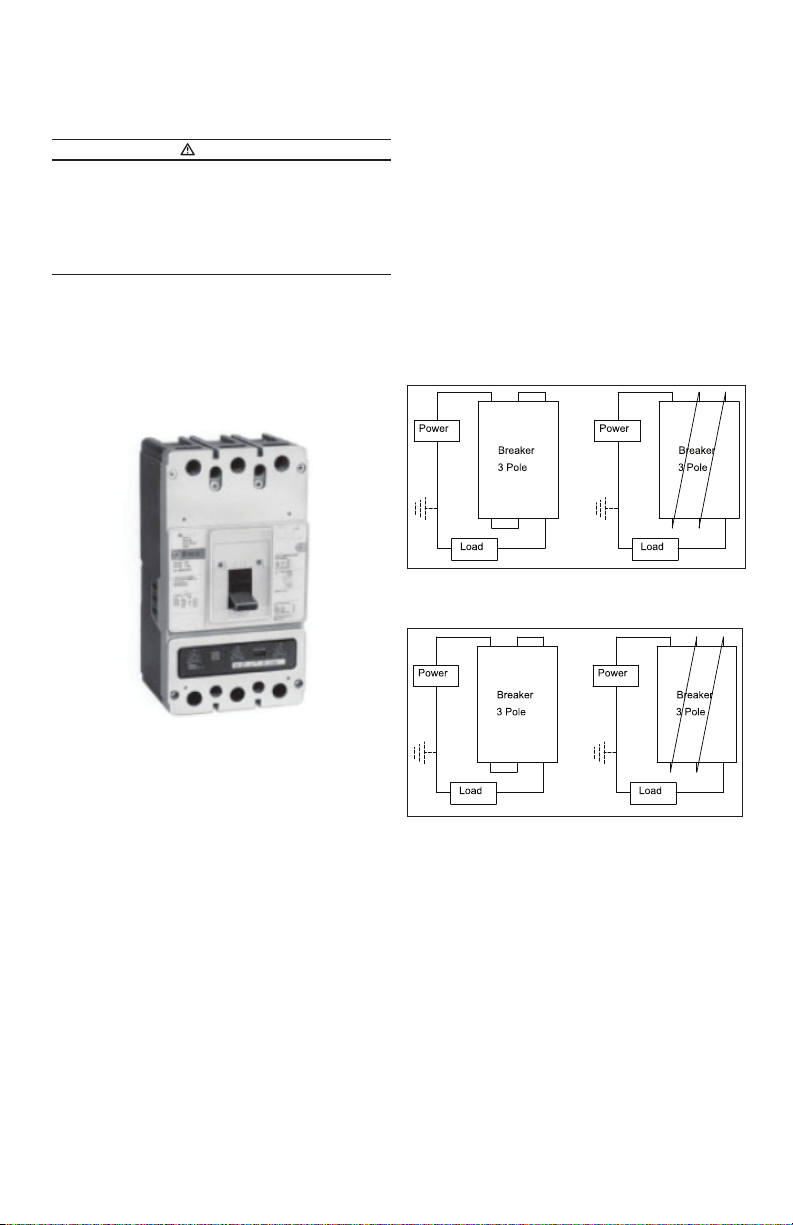
2-7. Connect line and load conductors and accessory leads.
2-8. If required, install terminal shield on circuit breaker cover with
mounting screws provided.
2-9. After the circuit breaker is installed, check all mounting hard-
ware and terminal connecting hardware for correct torque loading.
Torque values for line/load terminals are given in Table 2 and on the
circuit breaker nameplate.
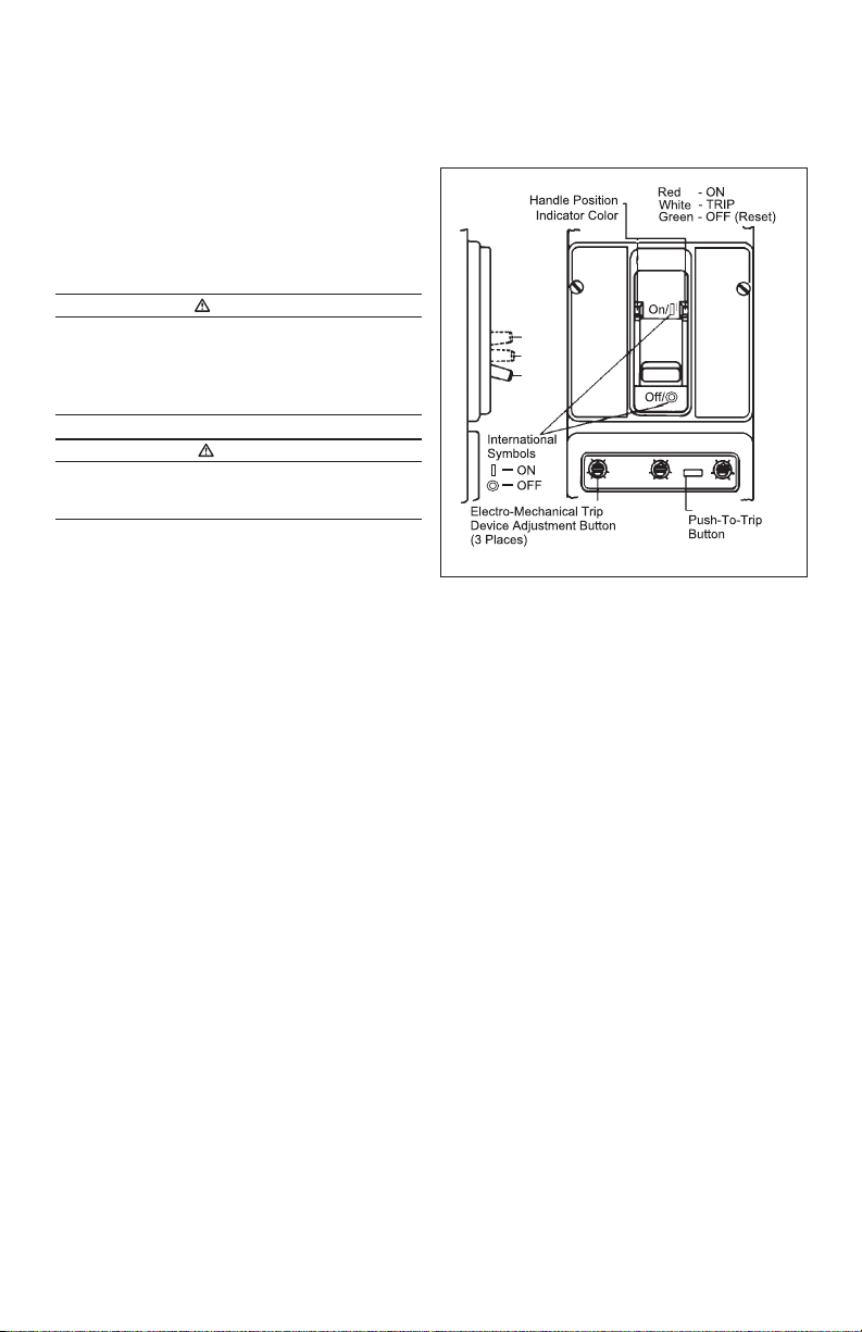
Manual Operation
Manual operation of the circuit breaker is controlled by the circuit
breaker handle and the PUSH-TO-TRIP button in the trip unit.The cir-
cuit breaker handle has three positions, two of which are shown on
the cover with raised lettering to indicate ON and OFF. On the sliding
handle barrier, ON, OFF, and trip are also shown by a color-coded
strip for each circuit breaker handle position: red for ON, white for
tripped, and green for OFF. (See Fig. 12 ).
Circuit Breaker Reset
After an automatic or accessory initiated trip, or a manual PUSH-
TO-TRIP operation, the circuit breaker is reset by moving the circuit
breaker handle to the extreme OFF position.
NOTICE
IN THE EVENT OF A THERMAL TRIP IN A THERMAL MAGNETIC TYPE TRIP
UNIT, THE CIRCUIT BREAKER CANNOT BE RESET UNTIL THE THERMAL
ELEMENT IN THE TRIP UNIT COOLS. NO CIRCUIT BREAKER SHOULD BE
RECLOSED UNTIL THE CAUSE OF TRIP IS KNOWN AND THE SITUATION
RECTIFIED.
PUSH-TO-TRIP Button
The PUSH-TO-TRIP button checks the circuit breaker tripping func-
tion and is used to periodically exercise the operating mechanism in
thermal-magnetic trip units. The button is designed to be operated
by a small screwdriver.
Trip Units
For additional information on thermal-magnetic trip units, refer to l.L.
29C603 (IL supplied with trip unit.)
6
Instruction Leaflet IL 29C702E
Eective April 2015
Installation Instructions for the HKDDC
Circuit Breaker and Molded Case Switch
EATON CORPORATION www.eaton.com
3. Inspection and FieldTesting
Series C molded case circuit breakers are designed to provide years
of almost maintenance-free operation. The following procedure
describes how to inspect and test a circuit breaker in service.
Inspection
Circuit breakers in service should be inspected periodically. The
inspection should include the following checks 3-1 through 3-8.
WARNING
BEFORE INSPECTING THE CIRCUIT BREAKER IN AN ELECTRICAL SYSTEM,
MAKE SURE THE CIRCUIT BREAKER IS SWITCHED TO THE OFF POSITION
AND THAT THERE IS NO VOLTAGE PRESENT WHERE WORK IS TO BE
PERFORMED. SPECIAL ATTENTION SHOULD BE PAID TO REVERSE FEED
APPLICATIONS TO ENSURE NO VOLTAGE IS PRESENT. THE VOLTAGES
IN ENERGIZED EQUIPMENT CAN CAUSE SEVERE PERSONAL INJURY OR
DEATH.
CAUTION
MAKE SURE THAT CLEANING AGENTS OR SOLVENTS USED TO CLEAN
THE CIRCUIT BREAKER ARE SUITABLE FOR THE JOB. SOME COMMERCIAL
CLEANING AGENTS WILL DAMAGE THE NAMEPLATES OR MOLDED
PARTS.
3-1. Remove dust, dirt, soot, grease, or moisture from the surface
of the circuit breaker using a lint-free dry cloth, brush, or vacuum
cleaner. Do not blow debris into circuit breaker. If contamination is
found, look for the source and eliminate the problem.
3-2. Switch circuit breaker to ON and OFF several times to be sure
that the mechanical linkages are free and do not bind. If mechanical
linkages are not free, replace circuit breaker.
3-3. With the circuit breaker in the ON position, press the PUSH
TO-TRIP button to mechanically trip the circuit breaker. Trip, reset,
and switch circuit breaker ON several times. If mechanism does
not reset each time the circuit breaker is tripped, replace the circuit
breaker.
3-4. Check base, cover, and operating handle for cracks, chipping,
and discoloration. Circuit breakers should be replaced if cracks or
severe discoloration is found.
3-5. Check terminals and connectors for looseness or signs of over-
heating. Overheating will show as discoloration, melting, or blister-
ing of conductor insulation, or as pitting or melting of conductor
surfaces due to arcing.
If there is no evidence of overheating or looseness, do not disturb or
tighten the connections. If there is evidence of overheating, termina-
tions should be cleaned or replaced. Before re-energizing the circuit
breaker, all terminations and cable should be refurbished to the con-
dition when originally installed.
3-6. Check circuit breaker mounting hardware, and tighten if neces-
sary.
3-7. Check area where circuit breaker is installed for any safety haz-
ards, including personal safety and re hazards. Exposure to certain
types of chemicals can cause deterioration of electrical connections.
FieldTesting
Any eld testing should be done in accordance with applicable
NEMA Standards.
Figure 12. Circuit Breaker Manual Controls.
7
Instruction Leaflet IL 29C702E
Eective April 2015
Installation Instructions for the HKDDC
Circuit Breaker and Molded Case Switch
EATON CORPORATION www.eaton.com
Notes:
Instruction Leaflet IL 29C702E
Eective April 2015
Installation Instructions for the HKDDC
Circuit Breaker and Molded Case Switch
Eaton Corporation
Electrical Group
1000 Cherrington Parkway
Moon Township, PA 15108
United States
877-ETN-CARE (877-386-2273)
Eaton.com
© 2015 Eaton Corporation
All Rights Reserved
Printed in Dominican Republic
Publication No. IL 29C702E
Part No. 6632C96H06
April 2015
Eaton is a registered trademark of Eaton
Corporation.
All other trademarks are property of their
respective owners.
The instructions for installation, testing, maintenance, or repair
herein are provided for the use of the product in general commercial
applications and may not be appropriate for use in nuclear applica-
tions. Additional instructions may be available upon specic request
to replace, amend, or supplement these instructions to qualify them
for use with the product in safety-related applications in a nuclear
facility.
The information, recommendations, descriptions, and safety nota-
tions in this document are based on Eaton’s experience and judg-
ment with respect to Retrotting of Power Breakers.This instruction-
al literature is published solely for information purposes and should
not be considered all-inclusive. If further information is required, you
should consult an authorized Eaton sales representative.
The sale of the product shown in this literature is subject to the
terms and conditions outlined in appropriate Eaton selling policies
or other contractual agreement between the parties.This literature
is not intended to and does not enlarge or add to any such contract.
The sole source governing the rights and remedies of any purchaser
of this equipment is the contract between the purchaser and Eaton.
NOWARRANTIES, EXPRESSED OR IMPLIED, INCLUDING
WARRANTIES OF FITNESS FOR A PARTICULAR PURPOSE OR
MERCHANTABILITY, ORWARRANTIES ARISING FROM COURSE
OF DEALING OR USAGE OFTRADE, ARE MADE REGARDING
THE INFORMATION, RECOMMENDATIONS, AND DESCRIPTIONS
CONTAINED HEREIN. In no event will Eaton be responsible to the
purchaser or user in contract, in tort (including negligence), strict
liability or otherwise for any special, indirect, incidental or conse-
quential damage or loss whatsoever, including but not limited to
damage or loss of use of equipment, plant or power system, cost
of capital, loss of power, additional expenses in the use of existing
power facilities, or claims against the purchaser or user by its cus-
tomers resulting from the use of the information, recommendations
and description contained herein.

Other Eaton Circuit Breaker manuals

Eaton E-PKZ0 Manual

Eaton

Eaton E-PKZ0 Manual

Eaton Power Xpert User manual

Eaton

Eaton Power Xpert User manual

Eaton NZM-XCM Manual

Eaton

Eaton NZM-XCM Manual

Eaton TA602LD Manual

Eaton

Eaton TA602LD Manual

Eaton DX-SIN3 A Series Manual

Eaton

Eaton DX-SIN3 A Series Manual

Eaton PKZM0 SP-65KA Series Manual

Eaton

Eaton PKZM0 SP-65KA Series Manual

Eaton L-PKZ0 Series Manual

Eaton

Eaton L-PKZ0 Series Manual

Eaton BRCAFLOFF Manual

Eaton

Eaton BRCAFLOFF Manual

Eaton DILM65-XIP2X Manual

Eaton

Eaton DILM65-XIP2X Manual

Eaton IZM Series User manual

Eaton

Eaton IZM Series User manual

Eaton FAZ-XHIN11 User manual

Eaton

Eaton FAZ-XHIN11 User manual

Eaton Power Defense 32-NF Manual

Eaton

Eaton Power Defense 32-NF Manual

Eaton VR Series Manual

Eaton

Eaton VR Series Manual

Eaton NZM2-XKR Manual

Eaton

Eaton NZM2-XKR Manual

Eaton VR+ Series User manual

Eaton

Eaton VR+ Series User manual

Eaton DILMS40-DILMS65 Series Manual

Eaton

Eaton DILMS40-DILMS65 Series Manual

Eaton NHI-E Series Manual

Eaton

Eaton NHI-E Series Manual

Eaton Power Defense PDC Series Manual

Eaton

Eaton Power Defense PDC Series Manual

Eaton IZM63 User manual

Eaton

Eaton IZM63 User manual

Eaton IZM-KLP-SO-RONIS User manual

Eaton

Eaton IZM-KLP-SO-RONIS User manual

Eaton Power Defense PDG4XROP Series Manual

Eaton

Eaton Power Defense PDG4XROP Series Manual

Eaton Cutler-Hammer VCP-WR Series User manual

Eaton

Eaton Cutler-Hammer VCP-WR Series User manual

Eaton xComfort CSEZ-01/17 User manual

Eaton

Eaton xComfort CSEZ-01/17 User manual

Eaton CPKZ0 Series Manual

Eaton

Eaton CPKZ0 Series Manual

Popular Circuit Breaker manuals by other brands

Stahl 8562/54-246 Series operating instructions

Stahl

Stahl 8562/54-246 Series operating instructions

Westinghouse F-11 instructions

Westinghouse

Westinghouse F-11 instructions

DRIESCHER-WEGBERG VSS Addition to Operation and Assembly Instructions

DRIESCHER-WEGBERG

DRIESCHER-WEGBERG VSS Addition to Operation and Assembly Instructions

ABB SACE Emax 2 operating instructions

ABB

ABB SACE Emax 2 operating instructions

Circutor RECmax-CVM series instruction manual

Circutor

Circutor RECmax-CVM series instruction manual

WEG DWB600 manual

WEG

WEG DWB600 manual

FRANKLINWH CSR2100 user manual

FRANKLINWH

FRANKLINWH CSR2100 user manual

Siemens SENTRON 3WL Reference manual

Siemens

Siemens SENTRON 3WL Reference manual

Siemens FSV Instructions, Installation, Operation, Maintenance

Siemens

Siemens FSV Instructions, Installation, Operation, Maintenance

Hyundai HVF Series instruction manual

Hyundai

Hyundai HVF Series instruction manual

Leviton 46596 Installation

Leviton

Leviton 46596 Installation

ETI ETITEC B T12 installation instructions

ETI

ETI ETITEC B T12 installation instructions

Kohler 31613437201NE quick start guide

Kohler

Kohler 31613437201NE quick start guide

Lovato SMX 11 Series Mounting instructions

Lovato

Lovato SMX 11 Series Mounting instructions

Leviton LP420-CBW installation instructions

Leviton

Leviton LP420-CBW installation instructions

Siemens VT160 operating instructions

Siemens

Siemens VT160 operating instructions

brennenstuhl BDI-A 30 GB 3210 Directions for use

brennenstuhl

brennenstuhl BDI-A 30 GB 3210 Directions for use

Siemens TSLN3M manual

Siemens

Siemens TSLN3M manual

manuals.online logo
manuals.online logoBrands
  • About & Mission
  • Contact us
  • Privacy Policy
  • Terms and Conditions

Copyright 2025 Manuals.Online. All Rights Reserved.