CPI 1194 Series User manual

4096-394
October 20, 2020
REVISION K
ASSEMBLY MANUAL
1.8 METER
SERIES 1194 ANTENNA SYSTEM
SATCOM & Antenna Technologies Inc.
1700 Cable Drive NE
Conover, NC 28613 USA
t +1 704-462-7330
f +1 704-462-7380
www.cpii.com

4096-394
CPI Satcom & Antenna Technologies 1.8M SERIES 1194
2
1.8 METER SERIES 1194
ANTENNA SYSTEM
K
Updated to CPI Format.
10/20/20
R.F.
J
Add Conover Address
4/20/16
RAH
I
Revise Cut Screws callout from 8 to 6 Pg 10
8/4/08
RAH
H
Rev HDWE 8043-032 to 8043-036
5/19/08
RAH
G
Revise Address
1/14/02
RAH
F
Revise Flat washers to 8
5/15/01
RAH
-
ORIGINAL RELEASE
02/02/95
R. Frye
REV.
DESCRIPTION
DATE
APPROVED

4096-394
CPI Satcom & Antenna Technologies 1.8M SERIES 1194
3
1.8M SERIES 1194 ANTENNA SYSTEM
TABLE OF CONTENTS
SECTION I GENERAL INFORMATION....................................................................... 5
1.0 INTRODUCTION ....................................................................................... 5
1.1 UNPACKING AND INSPECTION ............................................................. 5
1.2 FREIGHT DAMAGE.................................................................................. 5
1.3 MATERIAL - MISSING OR DAMAGED.................................................... 5
1.4 MECHANICAL INSTALLATION TOOLS .................................................. 6
1.5 FOUNDATION INTERFACE ..................................................................... 6
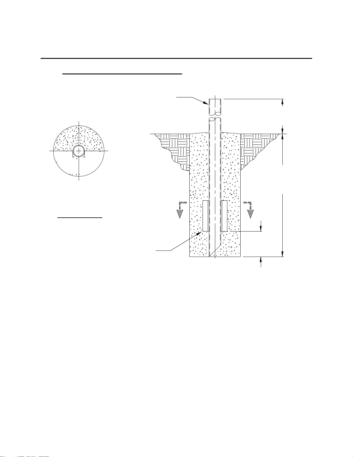
1.6 SUGGESTED MAST & FOUNDATION..................................................... 7
SECTION II ANTENNA SYSTEM ASSEMBLY............................................................. 9
2.0 ANTENNA ASSEMBLY ............................................................................ 9
2.1 FEED SUPPORT ASSEMBLY................................................................ 14
SECTION III ANTENNA POINTING............................................................................. 18
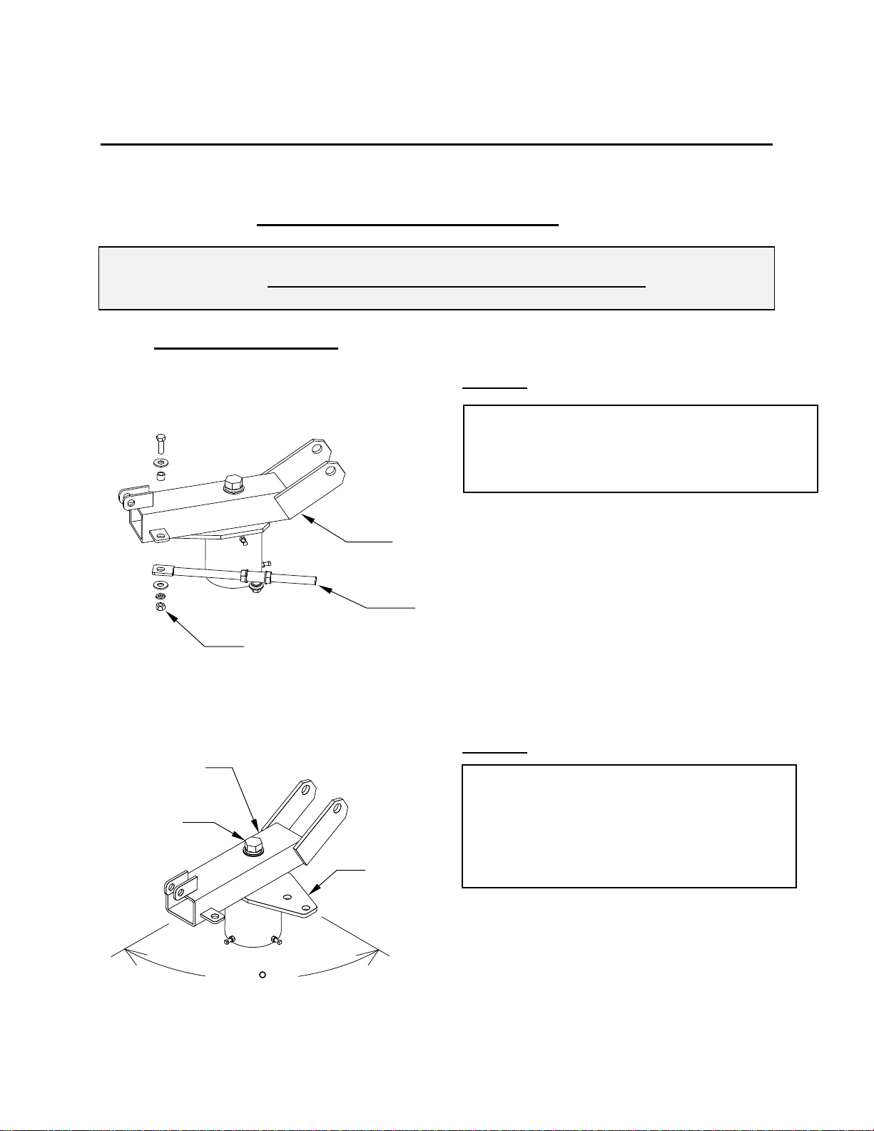
3.0 ANTENNA POINTING............................................................................. 18
SECTION IV MAINTENANCE ...................................................................................... 20
4.0 MAINTENANCE OVERVIEW.................................................................. 20
4.1 PERIODIC INSPECTION......................................................................... 20
4.2 REFLECTOR........................................................................................... 20
4.3 MOUNT AND REFLECTOR SUPPORT STRUCTURE........................... 21
4.4 FEED AND FEED SUPPORT.................................................................. 21

4096-394
CPI Satcom & Antenna Technologies 1.8M SERIES 1194
4

4096-394
CPI Satcom & Antenna Technologies 1.8M SERIES 1194
5
SECTION I GENERAL INFORMATION
1.0 INTRODUCTION
This manual describes the assembly and installation of CPI’s 1.8M Rx/Tx offset
antenna system with an Az/El mount (series number 1194). The CPI 1.8M is a
rugged, reliable antenna system, which will operate in the 10.95 to 12.75 and 14.0
to 14.5 GHz frequency bands for Ku-Band systems with high efficiency and at the
same time successfully withstand the effects of the environment.
These instructions are listed by sections that cover all areas of assembly and
installation. Additional sections are included in the manual to provide information
on antenna alignment to the satellite and maintenance.
1.1 UNPACKING AND INSPECTION
The antenna containers should be unpacked and inspected at the earliest date to
ensure that all material has been received and is in good condition. A complete
packing list for each major component is supplied.
1.2 FREIGHT DAMAGE
Any damage to materials while in transit should be immediately directed to the
freight carrier. He will instruct you on matters regarding any freight damageclaims.
1.3 MATERIAL - MISSING OR DAMAGED
Any questions regarding missing or damaged materials that is not due to the freight
carrier should be directed to CPI’s Customer Service Department at:
CPI Satcom & Antenna Technologies
1700 Cable Drive NE
Conover NC 28613 USA
Phone 770-689-2040
www.cpii.com

4096-394
CPI Satcom & Antenna Technologies 1.8M SERIES 1194
6
1.4 MECHANICAL INSTALLATION TOOLS
The hardware supplied with this antenna system is U.S. SAE standard size.
However, the sizes have been chosen to allow use with compatibly sized metric
wrenches as shown in the table below.
HARDWARE SIZE
SAE WRENCH
SIZE
METRIC WRENCH
SIZE
MAXIMUM REC.
TORQUE
5/16" BOLT
1/2"
13 mm
12 ft-lbs
(1.66 kg-m)
1/2" BOLT
3/4"
20 mm
45 ft-lbs
(6.20 kg-m)
3/4" NUT
1-1/8"
28 mm
160 ft-lbs
(22.07 kg-m)
1" BOLT
1-1/2"
38 mm
220 ft-lbs
(30.34 kg-m)
Also recommended for installation:
Inclinometer
Compass
Adjustable Wrench
1.5 FOUNDATION INTERFACE
The required interface from the foundation to the mount is 5" schedule 40 pipe
(5.56" or 14.12 cm O.D.). A suggested in-ground foundation is shown in
Figure 1.

4096-394
CPI Satcom & Antenna Technologies 1.8M SERIES 1194
7
1.6 SUGGESTED MAST & FOUNDATION
FIGURE 1.
NOTES:
1. 2 x 2 x 1/4 HRS Angle and schedule 40 pipe should conform with ASTM A36 and ASTM A53
Type E and S Grade B.
2. All concrete should conform to building code standards and have a
minimum compressive strength of 3000 PSI at 28 days. (Per ACI-318-77)
3. Soil bearing capacity should be no less than 2000 PSF.
4. Concrete should be poured against undisturbed soil.
5. Allow concrete 24 hours set time before installation of antenna.
6. The antenna should be properly grounded to meet applicable local codes.
7. Minimum depth as shown or extend to local frost line.
8. Foundation meets the design requirements as set forth by the uniform building code.
(1982 edition)
(CPI DOES NOT REPRESENT OR WARRANT THAT ANY PARTICULAR DESIGN OR SIZE OF
FOUNDATION IS APPROPRIATE FOR ANY LOCALITY OR EARTH STATION INSTALLATION.
2-5
TYP 2
42.0”
(107 cm)
42.0”
(107cm)
See Note #7
A
A
12.0”
(30.5cm)
24.0”
(70cm)
5” (12.7cm) SCH 40 PIPE
5.56”OD (14.12cm OD)
2” x 2” x 1 / 4” HRS Angle
12” Long (TYP 2 PLACES)
5cm x 5cm x .65cm Angle
30.5cm Long (TYP 2 PLACES)
SECTION A-A
2-5
TYP 2

4096-394
CPI Satcom & Antenna Technologies 1.8M SERIES 1194
8
PARTS LIST - 1.8M ANTENNA ASSEMBLY
ITEM NO.
PART NO.
DESCRIPTION
QTY
1
VARIES
1.8M Reflector
1
2
0181-648
Az/El Positioner Assembly
1
3
0181-649
Reflector Support Tube
1
4
0247-169
Reflector Cross Arms
2
5
8043-014
4
6
8043-036
4
7
8104-007
8
8
8202-043
8
9
8201-043
8
1/2” x 1.75 Crg Bolt
1/2” x 4.50 Carriage Bolt
1/2” Hex Nut
1/2” Lockwasher
1/2” washer

4096-394
CPI Satcom & Antenna Technologies 1.8M SERIES 1194
9
SECTION II ANTENNA SYSTEM ASSEMBLY
CAUTION: During the assembly procedure, the sequence of instructions must be
followed. Do Not Tighten Any Hardware Until Instructed. Refer to
the antenna assembly parts list and the following steps.
2.0 ANTENNA ASSEMBLY
STEP 1:
STEP 2:
A). Remove azimuth rod from positioner
assembly.
B). Set azimuth rod and related hardware aside.
Existing Hardware
Azimuth Rod
Positioner Assembly
A). Loosen rotation bolt on top of positioner.
B). Rotate the positioner so that the canister
plate is oriented as shown.
C). Lightly tighten rotation bolt.
90
Rotation
Bolt
Canister
Plate
Positioner

4096-394
CPI Satcom & Antenna Technologies 1.8M SERIES 1194
10
STEP 3:
STEP 4:
STEP 5:
A). Place positioner assembly onto mast
pipe.
B). Orient the positioner assembly
approximately towards the center of
the satellite orbital arc to within +/- 10°
as shown.
C). Securely tighten [6] canister screws.
D). Tighten [6] lock nuts against canister.
Mast Pipe
To Satellite (within +/- 10°)
Positioner Assembly
Canister Screws
Lock Nuts
A). Locate azimuth rod (step 1.) and loosen
the 3 / 4” nuts to allow movement of the azimuth
tube.
B). Remove 1 / 2” hardware from azimuth
tube and set aside.
1 / 2” Hardware
Azimuth Tube
3 / 4” Nuts
Azimuth
Rod
A). Locate end hole on canister plate.
B). Position azimuth tube in hole and secure
with 1 / 2” hardware from step 4.
1 / 2” Hardware
Canister Plate
Azimuth Tube

4096-394
CPI Satcom & Antenna Technologies 1.8M SERIES 1194
11
STEP 6:
STEP 7:
A). Rotate azimuth rod or the positioner so
that the hole in the azimuth rod and the hole in the
tab on the side of the positioner
are lined up.
B). Secure the azimuth rod to the positioner
with the 1 / 2” hardware removed in step 1.
C). Lightly tighten all of the azimuth adjustment
hardware at this time.
1 / 2” Hardware
Positioner
Azimuth Rod
A). Remove 1” hardware form the reflector
support tube.
B). Remove 1 / 2” hardware from the elevation
adjustment block and set aside.
1” Hardware
Reflector
Support Tube
1 / 2” Hardware
Elevation Adjustment Block

4096-394
CPI Satcom & Antenna Technologies 1.8M SERIES 1194
12
STEP 8:
STEP 9:
STEP 10:
A). Loosen 3/4” nuts on elevation rod
to allow movement of the elevation
block.
B). Slide elevation block down the elevation
rod and position the block in between
the small tabs on the positioner so that
the holes in both block and tabs are
aligned.
Elevation Rod
Elevation Block
3/4” Nuts
A). Secure elevation block to Positioner with
1 / 2” hardware set aside in step 7.
Elevation Block
1 / 2” Hardware
A). Place the reflector support tube in between
the large tabs on the positioner as shown.
B). Line up the holes on the tabs with the
holes in the reflector support tube.
C). Secure the support tube to the positioner
with the 1” hardware.
Positioner
1” Hardware
Large Tabs
Reflector Support
Tube

4096-394
CPI Satcom & Antenna Technologies 1.8M SERIES 1194
13
STEP 11:
STEP 12:
A). Locate the top of the reflector and insert
2 carriage bolts (item 6 ) thru top two
holes on face of reflector as shown.
Top of Reflector
[ 6 ]
A). Attach reflector cross arms to the
reflector support tube with 1 / 2”
hardware (items: 5,7,8,9).
Note the orientation of cross arms.
Cross Arm
[ 7,8,9 ] 4 places
Reflector Support Tube
Cross Arm
[ 5 ]
4 places

4096-394
CPI Satcom & Antenna Technologies 1.8M SERIES 1194
14
STEP 13:
A). With a person on each side of the reflector,
lift the reflector up.
B). Position the reflector so that the 2 carriage
bolts (step 12) pass thru the two holes in
the top cross arm.
C). Loosely attach 1 / 2” hardware (items,7,8,9).
Note: the reflector is fully supported at
this time.
D). Insert the 2 remaining carriage bolts (item 6)
thru the two bottom reflector mounting
holes and thru holes in the bottom cross
arm
E). Secure with items: 7, 8 & 9.
F). Tighten all reflector mounting hardware per
torque specifications listed on page 6.
Top of Reflector
Cross Arm
(TOP)
Cross Arm
(BOTTOM)
[ 7,8,9 ]
4 places
[ 6 ]
Reflector Support Tube

4096-394
CPI Satcom & Antenna Technologies 1.8M SERIES 1194
15
2.1 FEED SUPPORT ASSEMBLY
These instructions are intended as a general reference for feed support
assembly. If your antenna system has specific feed support installation
instructions, then refer to them at this time.
PARTS LIST - 1.8M FEED SUPPORT
ITEM NO.
PART NO.
DESCRIPTION
QTY
1
VARIES
Feed Rod
2
2
VARIES
Feed Support Tube
1
3
8031-008
3
4
8031-026
1
5
8201-041
10
6
8202-041
6
7
8101-009
6
8
8038-006
2
5 / 16” x 1.00” Bolt
5 / 16” x 3.25” Bolt
5 / 16” Flatwasher
5 / 16” Lock Washer
5 / 16” Hex Nut
5 / 16” x .75” Carriage Bolt

4096-394
CPI Satcom & Antenna Technologies 1.8M SERIES 1194
16
CAUTION: During the assembly procedure, the sequence of instructions must
be followed. Do Not Tighten Any Hardware Until Instructed.
Refer to the feed support parts list and the steps shown below.
STEP 1:
STEP 2:
A). Attach feed rods to reflector with
( items: 3, 6, 7 ) and with [ 2 ] of
( item 5 ).
NOTE: The 2.00” flat end of the feed
mounts to the outside rim of
the reflector
Feed Rods
See Detail A
A). Mount feed support tube between the
feed support brackets with [ 2 ] of
( items: 8, 5, 6, 7 ).
Feed Support Tube
See Detail B

4096-394
CPI Satcom & Antenna Technologies 1.8M SERIES 1194
17
STEP 3:
STEP 4:
A). Connect the feed rods to the feed
support tube with ( items: 4, 6, 7 )
and with [ 2 ] of ( item 5 ).
See Detail C
Feed Rod
Feed Support Tube
A). Attach feed support tube to the
reflector with ( items: 3, 6, 7 )
and with [ 2 ] of ( item 5 ).
B). Tighten the hardware at the reflector
rim snugly ( Detail A ).
C). Tighten the hardware connecting
the feed rods to the feed support
tube ( Detail C ).
D). Tighten the hardware that connects
the feed support tube to the feed
support brackets ( Detail B ).
E). Tighten the hardware connecting
the feed support tube to the reflector
( Detail D ).
F). Refer to separate instructions for the
specific feed/ODE assembly to feed
support.
See Detail D
Feed Support
Tube

4096-394
CPI Satcom & Antenna Technologies 1.8M SERIES 1194
18
[ 7 ]
[ 5 ]
[ 5, 6, 7 ]
Reflector
Feed Rod
DETAIL A
[ 5, 6, 7 ]
Feed Support Tube
Feed Support
Brackets
[ 8 ]
[ 5, 6, 7 ]
DETAIL B
[ 4 ]
[ 5 ]
Feed Support Tube
[ 5, 6, 7 ]
Feed Rod
DETAIL C
DETAIL D
Reflector
[ 5 ]
[ 3 ]
[ 5, 6, 7 ]
Feed Support Tube
Feed Support
Bracket

4096-394
CPI Satcom & Antenna Technologies 1.8M SERIES 1194
19
SECTION III ANTENNA POINTING
3.0 ANTENNA POINTING
The 1.8meter reflector contains an elevation offset look angle. Therefore, when
the reflector apertureis perpendicular to the ground, the antenna isactually looking
17.3° in elevation. Refer to Figure 2.
Step 1: Place an inclinometer on the reflector support tube as shown in Figure 2.
The surface allows for the offset look angle and therefore a direct reading
can be taken for elevation.
Step 2: Adjust the reflector up or down in elevation by turning the two 3/4" hex nuts
at the elevation block until the desired elevation is read on the inclinometer.
Snug the hardware.
Step 3: Azimuth Adjustment: With the electronics set to acquire the satellite, rotate
the antenna in azimuth until the satellite is found. Snug the azimuth
adjustment hardware.
Step 4: Peak the antenna signal by fine adjustments made in both azimuth and
elevation until the optimum signal is achieved.
Step 5: Tighten all hardware used for adjustment.

4096-394
CPI Satcom & Antenna Technologies 1.8M SERIES 1194
20
FIGURE 2.
INCLINOMETER
AZIMUTH
ADJUSTMENT
ELEVATION
ADJUSTMENT
Table of contents
Other CPI Antenna manuals
Popular Antenna manuals by other brands

Kenwood
Kenwood SIRIUS CX-SR10 installation manual

TDK
TDK Multilayer Chip Antennas ANT1085-4R1 Specifications

BlueSky Mast
BlueSky Mast BST2-K-L104-GND-000 manual

Conrad
Conrad 94 06 66 operating instructions

Lippert Components
Lippert Components Hotspot OEM installation manual

Ayyeka
Ayyeka WA00222 installation guide

Cabletech
Cabletech ANT0525 owner's manual

MAS Elektronik
MAS Elektronik XORO HAN 800 quick start guide

FUNAI
FUNAI PK240D owner's manual

Belden
Belden Hirschmann BAT-ANT-N-5A-IP65 Mounting instructions

Sophos
Sophos APX 320X Mounting instructions

KVH Industries
KVH Industries TracVision M7 Replacement instructions