Burster DIGIFORCE 9311 User manual

OPERATION MANUAL
DIGIFORCE®9311
PROFIBUS Integration into TIA Portal
Manufacturer:
© 2018
burster
praezisionsmesstechnik gmbh & co kg
burster
praezisionsmesstechnik gmbh & co kg
Alle Rechte vorbehalten
Talstr. 1 - 5
P.O.Box 1432
76593 Gernsbach
76587 Gernsbach
Germany
Germany
Valid from:
01.08.2018
Tel.: +49-7224-645-0
Applies to:
DIGIFORCE®9311-VXXX2
Fax.: +49-7224-645-88
Email: info@burster.com
www.burster.com
2767-BA9311PRTIAEN-5770-071525

2of 27
Table of Contents
Introduction ..............................................................................................................................................................3
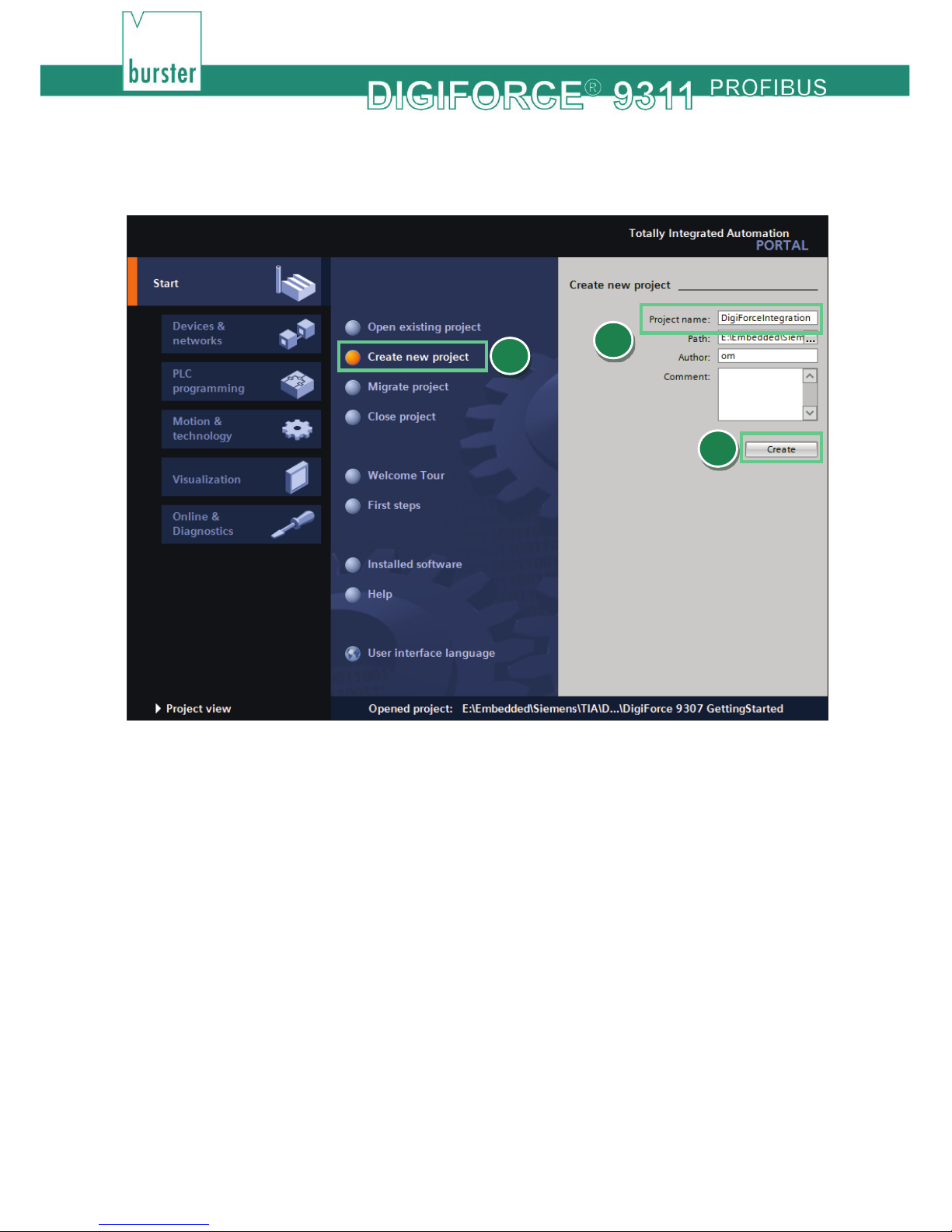
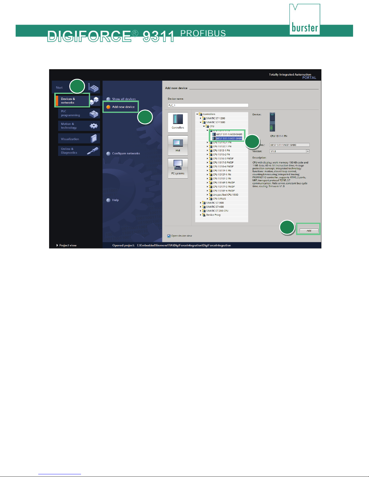
1. Creating new project.........................................................................................................................................4
2. Installation of GSD file ......................................................................................................................................6
3. Creation of network connections ......................................................................................................................7
4. Create a sample program:..............................................................................................................................13
5. Further Examples ...........................................................................................................................................18
5.1 Reading and Writing of string data types.................................................................................................19
5.2 Retrieving of measurement results ..........................................................................................................22
5.3 Changing of window limits .......................................................................................................................25

3of 27
Introduction
This quick start guide describes an approach how you can configure the DIGIFORCE®9311 via TIA Portal
using the example of S7-1511 CPU with a CM 1542-5 PROFIBUS Module. Please note that the samples
here cannot be directly used in your production line because they have beed extremely simplified to reach a
better understanding. Therefore, you may have to complete them by checking of status, error, length values
etc.
Please also note that you will have to use the DIGIFORCE®9311 PROFIBUS manual to get futher
information about input and output parameters (cyclic as well acyclic data transfer)

4of 27
1. Creating new project
Start the Totally Integrated Automation Protal, select Create New Project (a), assign the project
a name (b) and click Create (c):
a
b
c

5of 27
Go to Devices & networks (a) on the left side select Add new device (b) and look for yor CPU (c).
Afterwards click the Add button (d).
b
c
d
a

6of 27
2. Installation of GSD file
Note: Please make sure that your GSD file is compatible to the field bus firmware in the DIGIFORCE®
9311. Also for compatibility reasons, uninstall all previous GSD files of particular device if you have
any!
Go to Options->Manage general station description files (GSD)
Navigate to your DIGIFORCE®9311 GSD directory (a)(you will find the GSD files on burster DVD
that you got with your DIGIFORCE®9311 device or on burster.com), select the GSD file (b) and click
Install (c)
a
b
c
a

7of 27
3. Creation of network connections
Double click Device Configuration (a) in the project tree und switch to Network view (b) :
a
b

8of 27
Now select the DIGIFORCE®9311 device in the catalog and drag & drop it into the working area (a):
a

9of 27
Please select the port (pink rectangle) at the PROFIBUS module and hold the left mouse button
down to connect the module with DIGIFORCE®9311:
a

10 of 27
If the DIGIFORCE®9311 has not been automatically assigned to the master, click on the link “Not
assigned” (a) of DIGIFORCE®9311 and select your master (b):
a
b

11 of 27
Select the DIGIFORCE®9311 device, goto Device view (a) and click the tabs Properties ->
General (b). Finally select in the tree view on the left side PROFIBUS address (c) to see the
assigned PROFIBUS addresss (d)
Now you have to set this address in DIGIFORCE®9311 device. You can do it over our pc
configuration software DigiControl or directly in the device configuration menu Basic setup-
>PROFIBUS->Station address:
a
b
d
c

12 of 27
To select the I/O-Mode 11just drag the the I/O-Mode 1 entry from the hardware catalog into device
overview table:
1Please refer to the section Meaning of the content of the different protocol modes of DIGIFORCE® 9311 PROFIBUS manual to get more
information about available PROFIBUS DP-V0 Modes

13 of 27
4. Create a sample program:
In this section, you will learn how to create a simple program to start and stop a measurement periodically.
You will need to refer to sections 6.2 PLC inputs and 6.3 PLC outputs of DIGIFORCE®9311
PROFIBUS manual to understand the meaning of inputs and outputs bytes.
Expand the tree node Program blocks in the Project tree and double click Add new block:

14 of 27
Select in the new window Organization block (a) and then Cyclic interrupt (b). As language set
SCL (c), change the cyclic time to 1.000.000 µs (d) and click OK (e):
Type in the following source code in the code fild of the new block:
IF %Q2.0 = TRUE THEN // is IN_START (measurement start) set?
%Q2.0 := FALSE; // IN_START (measurement start) is set, then reset it
ELSE // IN_START is not set
IF %I2.0 = FALSE THEN // is OUT_READY (DIGIFORCE®9311 ready for measurement) set?
RETURN; // If not -> return
END_IF;// Else
%Q2.0 := TRUE; // set IN_START(measurement start)
END_IF;
Please note: the addresses may be different. You have to check them in the Device view->Device
overview of the DIGIFORCE®9311
a
b
c
d
e

15 of 27
You will also see that the TIA-Editor replaces the input/output addresses with tags. You can change
the tags names in PLC Tag table (e.g. to IN_START and OUT_READY):

16 of 27
Before you load the project into the CPU you have to set the IP addresse of your CPU. To do this
please go to Device view and select Ethernet addresses (a) in General tab. Set now the IP-
Address and a subnet mask(b) assigned to your in section IP-Protocol:
a
b

17 of 27
To load the configuration into the CPU select it first go to Online->Download to device and click on
Start search (a) to look for your controller. Then select the controller and click on Load (b):
The DIGIFORCE®9311 starts now a new measurement, waits a second, stops the measurement,
waits a second and starts the measurement again and so on.
Note: Make sure that PROFIBUS Control is enabled in DIGIFORCE®9311. For details, see chapter
3.5 Configuration menu in DIGIFORCE®9311 of DIGIFORCE®9311 PROFIBUS manual.
a
b

18 of 27
5. Further Examples
In the followed examples, a Hardware-ID is used to access a certain slot. To find this, please select a
DIGIFORCE®9311 device in Topology view or Network view and then switch to Device view. Click with
the right mouse button on the Slave module and select Properties:
You will see the hardware indentifier in the tab General:

19 of 27
5.1 Reading and Writing of string data types
In this example, we perform an indirect read access on slot 30/Subslot 1/index 10 to get the device type of
DIGIFORCE®9311 and then we will set the first nine characrters of this string as DIGIFORCE®9311 station
name on Slot 30/Subslot 1/Index 17. For these acyclic operations, you will need an instance of RDREC und
WRREC blocks. You can see the new station name in the info menu of DIGIFORCE®9311.
PLC parameters table:
Sourcecode:
#data[0] := 0; // Byte 0 of slot number to access
#data[1] := 30; // Byte 1 of slot number to access
REPEAT
"WRREC_DB"(REQ := TRUE,
ID := 281, // HW-ID of Slot 1 (see introduction of 'Further examples')
INDEX := 1, // Index 1: Slot number for indirect addressing
LEN := 2, // Length of data to write
DONE => #Done, // Write done
BUSY => #Busy, // Write not completed yet
ERROR => #Error, // Error
STATUS => #Status, // State
RECORD := #data); // Write the the slot number that must be accessed
UNTIL NOT #Busy AND #Done
END_REPEAT;
IF #Error = TRUE OR SHR(IN := #Status, N := 24) <> 0 THEN // Check Status and Error
RETURN;
END_IF;
REPEAT
"RDREC_DB"(REQ := TRUE,
ID := 281, // HW-ID of Slot 1 (see introduction of 'Further examples')
INDEX := 1, // Index 1
MLEN := 2, // Max. lenth of data to read
VALID => #Valid, // New Data Received and valid
BUSY => #Busy, // Read not completed yet
ERROR => #Error, // Error
STATUS => #Status, // State
LEN => #lenRead,// Number of bytes was read from device
RECORD := #data); // Read the current slot number from DIGIFORCE®9311
UNTIL NOT #Busy AND #data[1] <> 0 AND #data[0] <> 30 // Wait till the DIGIFORCE®9311 confirmed the slot
number
END_REPEAT;

20 of 27
IF #Error = TRUE OR SHR(IN := #Status, N := 24) <> 0 THEN // Check Status and Error
RETURN;
END_IF;
REPEAT
"RDREC_DB"(REQ := TRUE,
ID := 281, // HW-ID of Slot 1 (see introduction of 'Further examples')
INDEX := 10, // Read from index 10: Device Detection
MLEN := 18, // Max. lenth of data to read
VALID => #Valid, // New Data Received and valid
BUSY => #Busy,// Read not completed yet
ERROR => #Error, // Error
STATUS => #Status, // State
LEN => #lenRead, // Number of bytes was read from device
RECORD := #data); // Read data from slot 30 index 10
UNTIL NOT #Busy
END_REPEAT;
IF #Error = TRUE OR SHR(IN := #Status, N := 24) <> 0 THEN // Check Status and Error
RETURN;
END_IF;
REPEAT
"WRREC_DB"(REQ := TRUE,
ID := 281, // HW-ID of Slot 1(see introduction of 'Further examples')
INDEX := 17, // Slot 30, Index 17: station name
LEN := 9, // Lenth of data to write
DONE => #Done, // Write done
BUSY => #Busy, // Write not completed yet
ERROR => #Error, // Error
STATUS => #Status, // State
RECORD := #data); // Write data has been read from index 10 to index 17
UNTIL NOT #Busy AND #Done
END_REPEAT;
IF #Error = TRUE OR SHR(IN := #Status, N := 24) <> 0 THEN // Check Status and Error
RETURN;
END_IF;
Example 2: Writing of serial number SN1 into device order sheet
Note: Datatype String in TIA Portal contains two additional bytes, which represent the length of the string.
To avoid these two bytes being sent use the function ‘Strg_TO_Chars’ to convert the String to a byte array
as shown below:
PLC parameters table:
Other manuals for DIGIFORCE 9311
3
Table of contents
Other Burster Test Equipment manuals