CIS CRS354-48P User manual

CIS-CRS354-48P User Manual

2
Table of Contents
Welcome to Custom Integration Solutions ...............................................................................................................4
Overview...................................................................................................................................................................4
Package Contents....................................................................................................................................................4
Power........................................................................................................................................................................4
PoE Output ...............................................................................................................................................................4
Device Details...............................................................................................................................................................5
Ports..........................................................................................................................................................................5
LED Indicators..........................................................................................................................................................5
Buttons .....................................................................................................................................................................5
Input Power Requirements ....................................................................................................................................5
Mounting Instructions.................................................................................................................................................6
Quick Setup...................................................................................................................................................................7
Setup and Accessing the Web Interface....................................................................................................................8
The Status Page.......................................................................................................................................................9
Setting the Switch’s Identity..................................................................................................................................9
Undo / Redo ...........................................................................................................................................................10
Show / Hide Passwords ........................................................................................................................................10
Rebooting the Device............................................................................................................................................10
Changing the Default Password ..........................................................................................................................11
Setting the Time Zone...........................................................................................................................................11
IP Addressing.............................................................................................................................................................12
View the Switch’s IP Addresses ...........................................................................................................................12
CIS Support.............................................................................................................................................................12
Renewing the IP Address .....................................................................................................................................13
Setting a Static IP address...................................................................................................................................14
3
Interfaces ...................................................................................................................................................................16
Power Cycling an Ethernet Port ..........................................................................................................................16
VLANs...........................................................................................................................................................................17
Purchase VLAN configuration...............................................................................................................................17
Changing the VLAN on a Port on a Preconfigured System...............................................................................17
Manually Configuring the Switch for VLANs ...........................................................................................................18
Step 1 –Enable VLAN Filtering on the Bridge ...................................................................................................18
Step 2 –Assign the Trunk Port(s) .......................................................................................................................19
Step 3 –Assign Ports to VLANs............................................................................................................................20
Multicast Filtering –Prior to 6.48 ...........................................................................................................................21
Multicast Filtering –6.48 and Newer......................................................................................................................22
Multicast Querier ...................................................................................................................................................22
PoE Information and Settings..................................................................................................................................23
Enable/Disable PoE ...............................................................................................................................................23
Tools............................................................................................................................................................................24
UPnP........................................................................................................................................................................24
Ping.........................................................................................................................................................................24
IP Scan....................................................................................................................................................................25
Troubleshooting.........................................................................................................................................................26
Warranty Information................................................................................................................................................27
Contact Information..............................................................................................................................................27

4
Welcome to Custom Integration Solutions
Thank you for purchasing CIS devices. Our solutions make it easy for integrators to deploy networks in
home and business settings with minimal configuration. Our support team is here to assist with setting up
equipment and answering your network related questions.
Overview
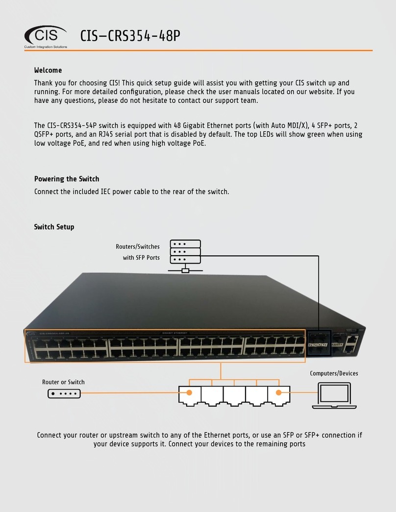
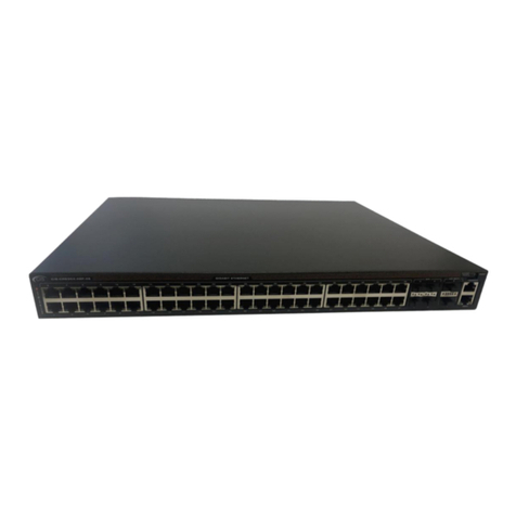
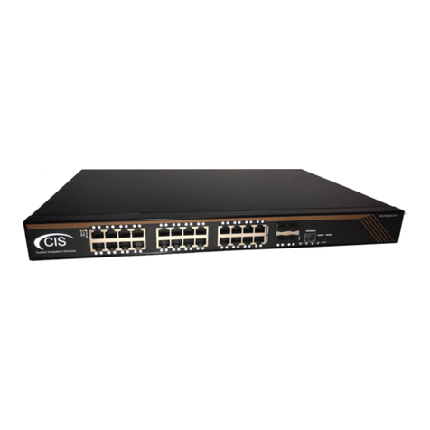
The CIS-CRS354-48P is a high-performance managed switch that provides plenty of connectivity for your
commercial applications. Each of the 48 Gigabit Ethernet ports provides PoE power for your devices.
In addition, there are 4 SFP+ ports (up to 10 Gbps), and 2 QSFP+ ports (up to 40 Gbps) to ensure there is
plenty of bandwidth between your network hardware.
Package Contents
Switch Power cable Rack ears (2) Screws (8)
Rack hooks (2)
Rack supports (2)
Power
The unit is equipped with one IEC type AC power input, which accepts 100-240 V power (~ 50/60 Hz 7 A
max). The power consumption of this device under maximum load is 800 W with attachments, 85 W
without attachments.
PoE Output
This device can supply PoE to external devices. The output voltage will be selected automatically,
depending on the voltage the connected device requires. The device can power both 802.3af/at devices
and devices that accept passive PoE power. If necessary, the output voltage can be switched manually.
By default, the PoE mode is set to auto. It will not damage non-PoE devices and will auto-detect devices
with PoE support and their required voltage. Once a PoE device is detected, it will be powered and the
PoE LEDs will turn on.
The switch can output a total of 1000 mA per port at <30 V, and 570 mA at >30 V. The total current output
at 26 V is 27A, and 13.2 A at 53V. The max wattage per port is 26 W at 26 V, and 30 W at 53 V

5
Device Details
Ports
•48 Gigabit Ethernet ports (With Auto MDI/X).
•4 SFP+ cages,
•2 QSFP+ cages
•RJ45 “Console” serial port (disabled).
LED Indicators
•Power LED - lit when the switch is powered on.
•Fault LED - indicates a fault has occurred. Contact CIS if this light is lit.
The top row LEDs indicate PoE out status.
•A green LED indicates that the respective port uses low voltage.
•A red LED indicates high voltage.
•A flashing green LED - indicates a problem with a low voltage device.
•A flashing red LED - indicates a problem with a high voltage device.
The bottom row LEDs indicate Ethernet and SFP port activity.
Buttons
Reset button: This button is located on the side next to the USB port. Hold this button while the device is
powered off, then apply power. Keeping holding until the USR LED light starts flashing, (5 seconds) then
release the button to reset to the default CIS configuration. You can use this procedure if you have
forgotten the password to access the device, or simply wish to return the unit to its default configuration
state.
Input Power Requirements
Supported input voltage-100V AC-240V AC.

6
Mounting Instructions
1. Attach the rack ears to the front sides of the switch with four screws per side.
2. Attach the rear support hooks to the rear sides of the switch with two screws per side.
3. Attach the rear rack ears to the rack with two screws on each side.
4. Move the switch into place using the rear supports to hold it. Attach the switch to the front of the
rack using two rack screws per side.

7
Quick Setup

8
Setup and Accessing the Web Interface
1. Connect the switch to your router using either an Ethernet or SFP cable. Do not connect both to
the router.
2. Connect your laptop or PC to any remaining Ethernet port on the front of the CIS switch
(excluding the console port). You can also access the web interface plugged directly into the
router.
3. To access the web interface, you must obtain the IP address assigned to the switch. Access your
router’s configuration page, then find the IP address assigned to the switch in the DHCP leases.
4. Launch a web browser and navigate to the IP address of the switch. To login, enter the username
cis and password integration.
5. Integrators may use the Get TeamViewer link if remote assistance is required.
integration

9
The Status Page
The status page provides basic diagnostic information. There is a CIS Support Address should you
require assistance. The switch’s Identity will show you which device you are accessing on your network.
You can view uptime, memory usage and load on the CPU.
Setting the Switch’s Identity
The identity is used to identify your device on the network. If you have multiple switches of the same
model, it is recommended you use a naming scheme to identify them.
The Identity setting can be found in the System tab in the left toolbar.

10
Undo / Redo
Undo and Redo buttons are located in the left toolbar. You may use them to quickly undo/redo any
changes made to configuration.
Show / Hide Passwords
Selecting the Hide Passwords button in the left toolbar will toggle the displaying of passwords related to
Wi-Fi, Hotspot, and more.
Rebooting the Device
If you are having ongoing issues with your network and suspect a reboot will help, the Reboot option
can be found in the System tab in the left toolbar. Clicking reboot will ask for confirmation before
proceeding.

11
Changing the Default Password
After you log in for the first time, please create a new a password to increase the security of the device.
Enter the old password in the top field and a secure password in the new and confirm password fields.
Setting the Time Zone
You can find the Clock settings under the System tab in the left toolbar. Select your time zone from the
drop-down menu.

12
IP Addressing
View the Switch’s IP Addresses
By default, the switch will acquire an IP address through DHCP. You can view the IP addresses in the IP >
Addresses section. In the picture below, there is an entry for a static address (optional), an entry for your
support IP address (if the support tunnel is enabled), and an entry for the IP address received via DHCP.
CIS Support
With the CIS Support tunnel activated, the CIS team can make configuration changes, push updates, and
troubleshoot your network. Press the button to the left of the entry. “D” stands for disable, while “E”
stands for enable.

13
Renewing the IP Address
To renew the IP address, select the DHCP Client section under the IP tab.
Click on the entry to bring up the options. Click the Renew button to obtain a new lease.

14
Setting a Static IP address
To set a static IP, select Addresses from the IP tab. Click on the field containing the disabled IP address.
If your network falls in one of the ranges below, you can set the static IP address yourself. If it is
outside of these ranges, you must call CIS to have a route created!
Available address ranges:
172.16.1.0/24
10.100.1.0/24
192.168.1.0/24
192.168.0.0/24
Enter the IP address to assign to the switch. Ensure that it is outside of the DHCP pool, and not in use by
other devices. The format must include /24 at the end. This is the subnet mask, which determines how
many devices can be connected to this network.

15
Once you have set the static IP address, disable the DHCP client. Go to the DHCP Client tab located under
IP in the toolbar. Click the “D” to disable the DHCP client.

16
Interfaces
To view the interface status, select Interfaces, then the Ethernet tab. The Ethernet tab provides an
overview of the activity on all ports. You can view the traffic sent and received, the status of PoE, PoE
settings, PoE priority and current being drawn by PoE devices.
Power Cycling an Ethernet Port
Click the Power Cycle button in the Interfaces > Ethernet section. Select the port and duration, then click
Power Cycle.

17
VLANs
VLANs provide isolation between your network devices. This can keep traffic from designated devices
secure and restricted from other devices on the network and reduce the overall congestion. It is highly
recommended to deploy VLANs for VoIP applications and systems that handle sensitive data.
Purchase VLAN configuration
For a complete VLAN model, the router, access points and switching all require additional configuration.
VLANs and additional networks are available on the CIS Store.
https://www.custom-integration-solutions.com/store/cis-vlan-interface/
https://www.custom-integration-solutions.com/store/cis-additional-network/
Changing the VLAN on a Port on a Preconfigured System
Select Bridge from the left toolbar, then click on the Ports tab. Select the port you wish to change the
VLAN on.
Enter the VLAN you wish the port to be a member of in the PVID field.

18
Manually Configuring the Switch for VLANs
When you purchase a VLAN configuration from CIS, these configuration changes will already be
implemented. If you wish to implement these changes yourself, follow the instructions below.
Step 1 –Enable VLAN Filtering on the Bridge
Select Bridge from the left toolbar. Select the bridge entry.
Enable the VLAN Filtering option. Click Apply, then OK.

19
Step 2 –Assign the Trunk Port(s)
Trunk ports carry traffic from all VLANs between your switches and routers. You must configure a trunk
port between the router and the switch.
With Bridge selected in the left toolbar, select the VLANs tab. Click Add New.
Enter the VLAN IDs the trunk will carry. You should enter the VLAN ID of every VLAN that will be present on
the network. Use the up/down arrows to add and remove VLAN IDs. Set each trunk port to be Tagged.

20
Step 3 –Assign Ports to VLANs
The ports that connect to your devices will be “untagged” ports or access ports. The final step is to set
which VLAN they will be a member of. With the Bridge section selected in the left toolbar, select the Ports
tab. Click on a port below.
Enter the VLAN number in the PVID field and click Apply, then OK.
Other manuals for CRS354-48P
1
Table of contents
Other CIS Switch manuals

CIS
CIS CRS326-24G User manual

CIS
CIS CRS112-8P User manual

CIS
CIS CRS328-24P User manual

CIS
CIS CIS-CRS112-8P User manual

CIS
CIS CIS-CRS354-48P User manual

CIS
CIS CIS-CRS328-24P User manual

CIS
CIS CIS-NW-POE4 User manual

CIS
CIS CRS354-48P User manual

CIS
CIS CRS326-24G Service manual

CIS
CIS CIS-SW-POE4 User manual
Popular Switch manuals by other brands

Raritan
Raritan Dominion KX 1.4 Faq

Broadcast Devices
Broadcast Devices AES-200 Technical reference manual

HIOTH TECHNOLOGY
HIOTH TECHNOLOGY CT-HAZB1029-SHB quick start guide

HP
HP ProCurve 1600M Installation and configuration guide

H3C
H3C S5170-EI Series manual

HP
HP FlexFabric 7900 Series installation guide