Cisco MERAKI MX67 User manual

MX67/MX68 Installation Guide
This document describes how to install and set up the MX67 and
MX68 security appliance. Additional reference documents are available
online at: www.meraki.com/library/products.
MX67/MX68 Overview
The Meraki MX67 and MX68 are enterprise security appliances
designed for distributed deployments that require remote administration.
It is ideal for network administrators who demand both ease of
deployment and a state-of-the-art feature set. A full overview of the
appliances' features can be found in the MX67 and MX68 Overview and
Specifications.
Package Contents
In addition to the MX device, the following are provided:
MX67/MX68 MX67W/MX68W
Power Adapter ( o Power Cable) Power Adapter ( o Power Cable)
2x CAT5 Ethernet Cables 2x CAT5 Ethernet Cables
Wall Screws and Anchors Wall Screws and Anchors
2x WiFi Antennae
MX67C MX68CW
Power Adapter ( o Power Cable) Power Adapter ( o Power Cable)
2x CAT5 Ethernet Cables 2x CAT5 Ethernet Cables
Wall Screws and Anchors Wall Screws and Anchors
1

MX67/MX68 MX67W/MX68W
2x LTE Antennae 2x Attached ( on-Removeable) Hybrid
WiFi+LTE Antennae
Front Panels
MX67/67C/67W
MX68/68W/68CW
Status Indicator
The MX67/MX68 series devices uses an LED to inform the user of the device's status. LED patterns and their meanings
are described below.
LED Status Meaning
Solid orange Power is applied but the appliance is not connected to
the Meraki Dashboard
Alternating Colors The appliance is attempting to connect to Meraki
Dashboard
2

Flashing White Firmware upgrade in progress
Solid White
Fully operational/connected, uplink actively using wired
WA
Solid Purple Fully operational/connected, uplink actively using
integrated cellular failover
Back Panels
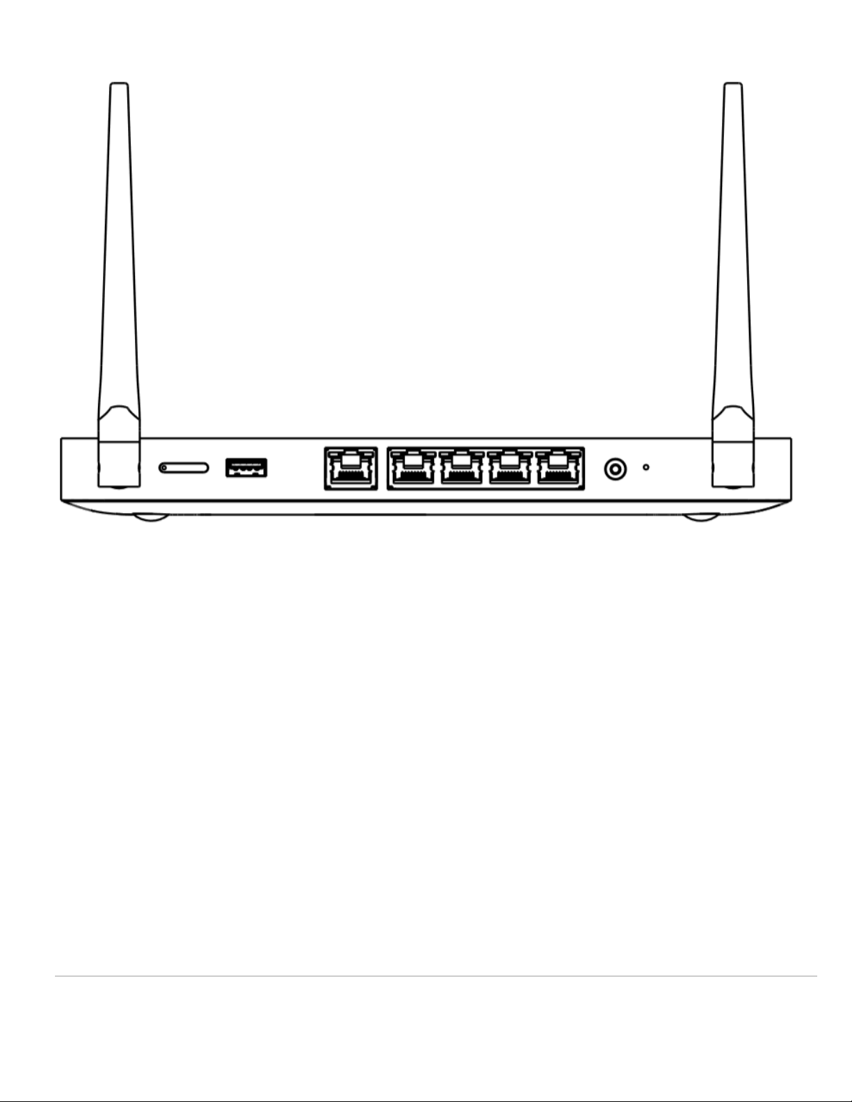
MX67
MX67C
3
MX67W
4
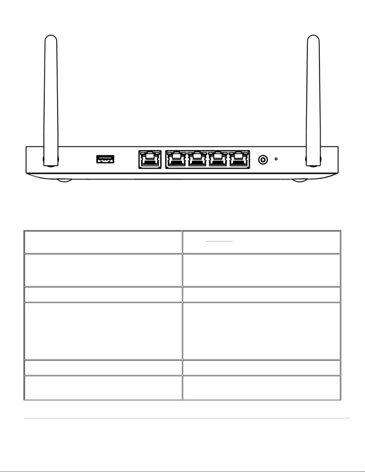
MX67/MX67W/MX67C Back Panel Functions
Additional functions on the back panel are described below, from left to right.
SIM Card Slot (MX67C) Active, supported SIM cards can be inserted into this
slot to enable cellular capabilities.
USB port USB 3.0 for external 3G/4G wireless modems. Traffic
status is indicated by the USB LED.
WAN / Internet port This port provides connectivity to the WA .
LAN ports
These 4 ports provide connectivity to computers,
printers, access points, or Ethernet switches.
A steady green LED indicates bidirectional connectivity,
and flashing green indicates traffic.
Power input Designed for use only with the unit’s power supply.
Reset button Insert a paper clip if a reset is required.
5

Press for 1 second to delete a downloaded configuration
and reboot.
Press and hold for more than 10 seconds to force a full
factory reset.
MX68
MX68W
MX68CW
6

MX68/MX68W/MX68CW Back Panel Functions
Additional functions on the back panel are described below, from left to right.
WAN / Internet ports These two ports provide connectivity to the WA .
LAN ports
These 8 ports provide connectivity to computers,
printers, access points, or Ethernet switches.
A steady green LED indicates bidirectional connectivity,
and flashing green indicates traffic.
PoE+ Ports
These 2 LA ports provide connectivity to computers,
printers, access points, or Ethernet switches.
Each port outputs up to 30W of PoE power.
A steady green LED indicates bidirectional connectivity,
and flashing green indicates traffic.
7

Power input Designed for use only with the unit’s power supply.
Reset button
Insert a paper clip if a reset is required.
Press for 1 second to delete a downloaded configuration
and reboot.
Press and hold for more than 10 seconds to force a full
factory reset.
Side Panels
MX68
MX68W
8

MX68CW
9

MX68/MX68W/MX68CW Side Panel Functions
Additional functions on the side panel are described below, from left to right.
SIM Card Slot (MX68CW) Active, supported SIM cards can be inserted into this
slot to enable cellular capabilities.
USB port USB 2.0 for 3G/4G wireless cards. Traffic status is
indicated by the USB LED.
Bottom Panel
Please note that the serial number is located on the product label at the bottom panel of MX67/MX68 devices
10

Mounting Hardware
The supplied wall screws and anchors allow you to mount the appliance on a drywall surface, either vertically or
horizontally. The distance between the holes you drill should be 5-1/8 inches (13 cm).
• For mounting on drywall, use a ¼-in drill bit, then insert the plastic and screw assemblies.
• For mounting on wood or a similar surface, use only the screws.
• Allow the heads of the screws to stick out far enough to be inserted securely into the back of the appliance.
Connecting to WA
All Meraki MX devices must have an IP address. This section describes how to configure your local area network before
you deploy it. A local management web service, running on the appliance, is accessed through a browser running on a
client PC. This web service is used for configuring and monitoring basic ISP/WA connectivity.
Setting up a Static IP Address
Do the following to configure basic connectivity and other networking parameters:
1. Using a client machine such as a laptop, connect to one of the LAN ports of the MX.
2. Using a browser on the client machine, access the appliance's built-in web service by browsing to
http://setup.meraki.com. (You do not have to be connected to the Internet to reach this address)
3. Click Uplink configuration under the Local status tab. The default credentials use the device serial number as
the username, with a blank password field.
4. Choose Static for the IP Assignment option.
5. Enter the IP address, subnet mask, default gateway IP and D S server information.
Setting up a DHCP IP Address
By default all MX devices are configured to DHCP from upstream WA / ISP servers. Simply plug the MX's WA /
Internet port to your upstream circuit and wait a few minutes for the unit to negotiate a DHCP address.
To ensure that the client PC is redirected to the local web service in the following step, you must disable all
other network services (ex: wi-fi) on your client machine.
When the WA connection is fully enabled, Internet LED 1 will turn green.
11

Setting up Cellular Failover
The MX67C and MX68CW have an embedded LTE module for cellular failover connections. The following section will
walk through first-time set-up of an MX with an internet connection as a primary connection and cellular as failover.
To set up the cellular failover connection, follow the steps below:
1. Power off the MX. Swapping/installing SIM cards while the MX is powered on may cause unexpected behavior or
errors
2. For the MX67C, connect the antennas for cellular reception. Antennae are pre-attached for the MX68CW
3. Open the SIM tray using the SIM card removal tool included in the box
4. Insert a nano SIM card (4FF size) and close the SIM tray
5. Connect the uplink for the MX device via a wired connection to connect to the Meraki cloud
6. Power on the MX and wait for the MX to show as online in the Meraki dashboard
7. Check with the carrier of choice if an AP needs to be configured. If so, do that from the Meraki Dashboard under
Security Appliance > Monitor > Appliance Status > Uplink tab
8. avigate to Security Appliance > Monitor > Appliance Status > Uplink tab and next to Status, select the edit
(pencil) button and then select Enabled. When the cellular uplink is successfully connected, you will be able to see
the status on the left hand side of the Appliance Status page and in the Uplink tab. The connection will say
Ready when it is successfully connected
9. Test the cellular failover connection by unplugging the wired connection or by using the traceroute tool under
Security Appliance > Monitor > Appliance Status in the Tools tab
10. If, after following the steps above, the SIM card is not detected, please confirm with your carrier that the SIM card
is active and has data. You will need the ICCID of the SIM card and IMEI of the device to get troubleshooting help
from the carrier
ote that the IMEI cannot yet be found on the Meraki dashboard, only on the physical label of the device. The
IMEI of the MXs with embedded LTE, as well as the serial number and MAC address, can be found on the
product label at the bottom of cellular-embedded MX devices.
12

◦ A list of certified carriers can be found in our MX67 and MX68 Overview and Specifications document
11. Please contact the Meraki Support team if the cellular connection is still not being recognized after following the
steps above
Additional Settings
Setting VLANs
If your WA uplink is on a trunk port, choose VLAN tagging > Use VLAN tagging and enter the appropriate value for
VLAN ID for your network.
Setting up a Secondary WAN Interface on the MX68
MX68 devices come with two dedicated Internet ports, which are both configured on the Security Appliance >
Appliance Status > Local Status under the Uplink Configuration.
Setting up a Secondary WAN interface on the MX67
You can toggle the LA 2 port between LAN and Internet, through Local Status Page
Setting PPPoE
PPPoE authentication may be required if you are connecting MX device to a DSL circuit. You need to know your
authentication option and credentials (supplied by your ISP) in order to complete these steps.
• Choose Connection Type > PPPoE.
• Select your Authentication option.
• If you select Use authentication, enter appropriate values for Username and Password.
Web Proxy Settings
These settings take effect if the MX device has to fall back to using HTTP to contact the Cloud Controller. By default,
web proxy is disabled. To enable web proxy, do the following:
• Choose Web proxy > Yes.
• Enter values as appropriate for Hostname or IP and Port.
• If you require authentication, choose Authentication > Use authentication, and enter appropriate values for
Username and Password.
Please note that all these settings below are accessible only via the local management console.
To apply all configuration settings to the appliance, be sure to click Save Settings at the bottom of the page.
13

Configuring Physical Link Settings
To configure physical link settings on the Ethernet ports, click Local status > Ethernet configuration. You can enable
half duplex, full duplex, and autonegotiation, as well as set 10- or 100-Mbps data rates.
14
This manual suits for next models
5
Table of contents
Other Cisco MERAKI Security System manuals


