manuals.online logo
Brands
  1. Home
  2. •
  3. Brands
  4. •
  5. Cisco
  6. •
  7. Network Hardware
  8. •
  9. Cisco SA520-K9 - SA 500 Series Security Appliances User manual

Cisco SA520-K9 - SA 500 Series Security Appliances User manual

Quick Start Guide
Cisco Small Business Pro
SA 500 Series Security Appliances
Package Contents
• SA500 Series Security Appliance
• Mounting Hardware
• Rubber Feet for Desktop Mounting
• Quick Start Guide
• Documentation CD-ROM
• Power Cord
Product Overview
Thank you for choosing a Cisco SA500 Series Security Appliance, a member
of the Small Business Family. The SA500 Series is a set of security appliances
that provide business-grade security gateway solutions with firewall, site-to-
site and remote access VPN support, and optional web and email security. The
SA520W model also includes 802.11n access point capabilities.
This guide describes the features of the security appliance, and helps you to
install the device in a standard configuration. Your particular model may not
have all of the features or functionality described in this guide. For more
detailed information on the individual models, refer to the SA500 Series
Security Appliances Administration Guide on Cisco.com. See the
documentation links in the “Where to Go From Here” section of this guide.
Front Panel
RESET Button—To reboot the security appliance, push and release the Reset
button. To restore the factory default settings, press and hold the Reset button
for 5 seconds.
DIAG LED—(Orange) When lit, indicates the appliance is performing the
power-on diagnostics. When off, indicates the appliance has booted properly.
POWER LED—(Green) When lit, indicates the appliance is powered on.
DMZ LED—(Green) When lit, indicates the Optional port is configured as a
separate LAN to host public ser vers.
SPEED LED—(Green or Orange) Indicates the traffic rate for the associated
port. Off = 10 Mbps, Green = 100 Mbps, Orange = 1000 Mbps.
LINK/ACT LED—(Green) When lit, indicates a connection is being made
through the port. When flashing, the port is active.
WLAN LED—(Green) When lit, indicates that wireless is enabled (SA520W).
1
Back Panel
POWER Switch—Turns the security appliance on or off.
POWER Connector—Connects the security appliance to power using the
supplied power cable.
LAN Ports—Connect PCs and other network appliances to the security
appliance. The SA520 and SA520W have 4 LAN ports. The SA 540 has 8.
OPTIONAL Port—Can be configured to operate as a WAN, LAN, or DMZ port.
A DMZ (Demilitarized Zone or Demarcation Zone) can be configured to allow
public access to services such as web servers without exposing your LAN.
WAN Port—Connects the security appliance to DSL, a cable modem, or
another WAN connectivity device.
USB Port—Connects the security appliance to a USB device. You can use a
USB device to store configuration files for backup and restore operations.
NOTE The back panel of the SA520W includes three threaded
connectors for the antennas.
Installation Options
You can place your security appliance on a desktop, mount it on a wall, or
mount it in a rack.
Placement Tips
• Ambient Temperature—To prevent the security appliance from
overheating, do not operate it in an area that exceeds an ambient
temperature of 104°F (40°C).
•AirFlow—Be sure that there is adequate air flow around the device.
•MechanicalLoading—Be sure that the security appliance is level and
stable to avoid any hazardous conditions.
To place the security appliance on a desktop, install the four rubber feet
(included) on the bottom of the security appliance. Place the device on a flat
surface.
2
Wall Mounting
STEP 1 Insert two 17 mm screws, with anchors, into the wall 15 cm apar t (about
5.9 inches). Leave 3-4 mm (about 1/8 inch) of the head exposed.
STEP 2 Position the unit so that the wall-mount slots are over the two screws.
Slide the unit down until the screws fit snugly into the wall-mount slots.
Rack Mounting
You can mount the security appliance in any standard size, 19-inch (about 48
cm) wide rack. Each security appliance requires 1 rack unit (RU) of space,
which is 1.75 inches (44.45 mm) high.
CAUTION Do not overload the power outlet or circuit when
installing multiple devices in a rack.
STEP 1 Remove the four screws from each side of the security appliance.
STEP 2 Place one of the supplied spacers on the side of the security appliance
so that the four holes align to the screw holes. Place a rack mount
bracket next to the spacer and reinstall the screws.
If the screws are not long enough to reattach the bracket with the
spacer, attach the bracket directly to the case without the spacer.
STEP 3 Install the security appliance into a standard rack as shown.
Americas Headquarters
Cisco Systems, Inc.
170 West Tasman Drive
San Jose, CA 95134-1706
USA
http://www.cisco.com
Tel: 408 526-4000
800 553-NETS (6387)
Fax: 408 527-0883
Cisco, Cisco Systems, the Cisco logo, and the Cisco Systems logo are registered trademarks or
trademarks of Cisco Systems, Inc. and/or its affiliates in the United States and certain other
countries. All other trademarks mentioned in this document or Website are the property of their
respective owners. The use of the word partner does not imply a partnership relationship between
Cisco and any other company. (0705R)
© 2009 Cisco Systems, Inc. All rights reserved.
Printed in the USA on recycled paper containing 10% postconsumer waste.
78-18996-02
Installation
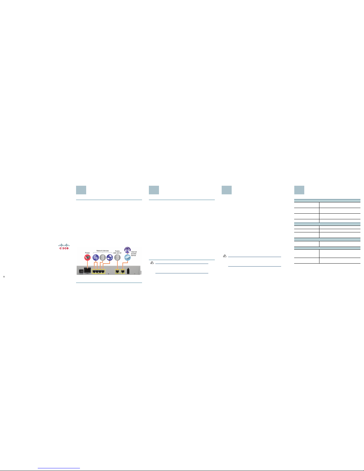
STEP 1 Connect the security appliance to power.
STEP 2 If you are installing the SA520W, screw each antenna onto a threaded
connector on the back panel. Orient each antenna to point upward.
STEP 3 For DSL, a cable modem, or other WAN connectivity devices, connect
an Ethernet network cable from the device to the WAN port on the
back panel. Cisco strongly recommends using Cat5E or better cable.
STEP 4 For network devices, connect an Ethernet network cable from the
network device to one of the dedicated LAN ports on the back panel.
STEP 5 For a UC500, connect an Ethernet network cable from the WAN port of
the UC500 to an available LAN port of the security appliance.
For details about configuring the UC500 and the security appliance to
work together, see the SA500 Series Security Appliances
Administration Guide on Cisco.com. See the documentation links in
the “Where to Go From Here” section of this guide.
STEP 6 Power on the security appliance.
STEP 7 Power on the connected devices. Each LED lights to show an active
connection.
A sample configuration is illustrated below.
Congratulations! The installation of the security appliance is complete.
3
Launching the Configuration
Utility
STEP 1 Connect your PC to an available LAN port on the back panel of the
security appliance.
Your PC will become a DHCP client of the security appliance and will
receive an IP address in the 192.168.75.x range.
STEP 2 Start a web browser. In the Address bar, enter the default IP address of
the security appliance: 192.168.75.1.
You can use Internet Explorer (version 6 and higher), Firefox, and Safari
(for Mac).
STEP 3 When the Security Alert appears, accept or install the certificate:
• Internet Explorer: Click Yes to proceed, or click View Certificate
for details. On the Certificate page, click Install the Certificate.
Follow the instructions in the Wizard to complete the installation.
•Firefox:Click the link to add an exception. Click the Add Exception
button. Click Get Certificate, and then click Confirm Security
Exception.
•Safari:Click Continue to proceed, or click Show Certificate. On
the Certificate page, click Install the Certificate. Follow the
instructions in the Wizard to complete the installation.
STEP 4 When the login page appears, enter the user name and password.
The default user name is cisco. The default password is cisco.
Passwords are case sensitive.
STEP 5 Click Login.
The Getting Started page of the Configuration Utility appears.
NOTE You also can launch the Configuration Utility from the Cisco
Configuration Assistant (CCA) if a CCA-supported device is
connected to your security appliance. For details, refer to
your CCA documentation.
4
Getting Started with the
Configuration
The security appliance is pre-configured with default settings that allow you to
begin using the device right away. However, you may wish to adjust these
settings or enable special features. The Configuration Utility includes a
Getting Started page that makes it easy to complete the most common
configuration tasks.
Typical tasks include:
• Configure the WAN and LAN connectivity.
• Upgrade the firmware.
• Change the default administrator password.
• Configure the security settings.
• Configure the VPN connections.
• Configure the wireless settings (SA520W).
Click a link on the Getting Started page to choose a task that you want to
perform. When the configuration page appears, enter the information, and then
click Apply to save your settings. Click Getting Started in the menu bar to
return to the Getting Started page.
To configure features that are not included on the Getting Started page, you
can use the buttons on the menu bar and the links in the navigation tree.
NOTE For complete details about configuring your security
appliance, refer to the SA500 Series Security Appliances
Administration Guide on Cisco.com. See the documentation
links in the “Where to Go From Here” section of this guide.
5
Where to Go From Here
Support
Cisco Small Business
Support Community
www.cisco.com/go/smallbizsupport
Online Technical Support
and Documentation
www.cisco.com/support (Log in required)
Cisco Small Business
Support and Resources
www.cisco.com/go/smallbizhelp
Phone Support Contacts www.cisco.com/go/sbsc
Software
Quick VPN Software www.cisco.com/go/qvpn
Cisco VPN Client www.cisco.com/go/ciscovpnclient
SA500 Firmware
Downloads
www.cisco.com/go/sa500software
Product Documentation
SA500 Technical
Documentation
www.cisco.com/go/sa500resources
Cisco Small Business
Cisco Partner Central for
Small Business (Partner
Login Required)
www.cisco.com/web/partners/sell/smb
Cisco Small Business
Home
www.cisco.com/smb
6

This manual suits for next models

1

Other Cisco Network Hardware manuals

Cisco Network Storage System NSS3000 Series User manual

Cisco

Cisco Network Storage System NSS3000 Series User manual

Cisco MERAKI CW9166D1 User manual

Cisco

Cisco MERAKI CW9166D1 User manual

Cisco NCS 2006 Manual

Cisco

Cisco NCS 2006 Manual

Cisco WS-CE500 - Catalyst Express 500-24PC Instruction Manual

Cisco

Cisco WS-CE500 - Catalyst Express 500-24PC Instruction Manual

Cisco TelePresence Service manual

Cisco

Cisco TelePresence Service manual

Cisco CSS11501 - 100Mbps Ethernet Load Balancing... User manual

Cisco

Cisco CSS11501 - 100Mbps Ethernet Load Balancing... User manual

Cisco C8510MSR-SKIT-DC - Catalyst 8510 Multiservice Switch... User manual

Cisco

Cisco C8510MSR-SKIT-DC - Catalyst 8510 Multiservice Switch... User manual

Cisco Fourth-Generation Versatile Interface Processor... Operator's manual

Cisco

Cisco Fourth-Generation Versatile Interface Processor... Operator's manual

Cisco MXE 3000 Manual

Cisco

Cisco MXE 3000 Manual

Cisco MX60 User manual

Cisco

Cisco MX60 User manual

Cisco Cisco ASA Series User manual

Cisco

Cisco Cisco ASA Series User manual

Cisco NCS 1010 Instruction sheet

Cisco

Cisco NCS 1010 Instruction sheet

Cisco Firepower 1010 User manual

Cisco

Cisco Firepower 1010 User manual

Cisco IDS-4230-FE - Intrusion Detection Sys Fast Ethernet... Operator's manual

Cisco

Cisco IDS-4230-FE - Intrusion Detection Sys Fast Ethernet... Operator's manual

Cisco LightStream 1010 User manual

Cisco

Cisco LightStream 1010 User manual

Cisco ONS 15310-MA SDH Manual

Cisco

Cisco ONS 15310-MA SDH Manual

Cisco ASR 901S Series Operating instructions

Cisco

Cisco ASR 901S Series Operating instructions

Cisco GS7000 Guide

Cisco

Cisco GS7000 Guide

Cisco GS7000 Operating instructions

Cisco

Cisco GS7000 Operating instructions

Cisco ONS 15454 M12 User manual

Cisco

Cisco ONS 15454 M12 User manual

Cisco ON100 Network Agent User manual

Cisco

Cisco ON100 Network Agent User manual

Cisco AIR-BR1410A-A-K9 - Aironet 1410 Wireless... Quick reference guide

Cisco

Cisco AIR-BR1410A-A-K9 - Aironet 1410 Wireless... Quick reference guide

Cisco NCS 2000 series User manual

Cisco

Cisco NCS 2000 series User manual

Cisco Aironet 340 Series User manual

Cisco

Cisco Aironet 340 Series User manual

Popular Network Hardware manuals by other brands

Appro NVR-2028 Installation & operating manual

Appro

Appro NVR-2028 Installation & operating manual

Win PL-80120 user manual

Win

Win PL-80120 user manual

Calix PH 500 Assembly instructions

Calix

Calix PH 500 Assembly instructions

DZS IMACS 3000 user guide

DZS

DZS IMACS 3000 user guide

HIK VISION DS-9000-ST user manual

HIK VISION

HIK VISION DS-9000-ST user manual

Watchguard Firebox T85-PoE Hardware guide

Watchguard

Watchguard Firebox T85-PoE Hardware guide

Promise SmartStor NS2300N quick start guide

Promise

Promise SmartStor NS2300N quick start guide

Beckhoff EPP9022-9060 Documentation

Beckhoff

Beckhoff EPP9022-9060 Documentation

Bosch D8125INV Operation and installation guide

Bosch

Bosch D8125INV Operation and installation guide

Sena HelloDevice Lite Series user guide

Sena

Sena HelloDevice Lite Series user guide

Westermo RT-610 HV user guide

Westermo

Westermo RT-610 HV user guide

Comtrend Corporation WAP-5922MP Quick install guide

Comtrend Corporation

Comtrend Corporation WAP-5922MP Quick install guide

ADTRAN 1442120G1 Job aid

ADTRAN

ADTRAN 1442120G1 Job aid

VC 16835 Mounting and operating manual

VC

VC 16835 Mounting and operating manual

SMC Sierra Monitor ProtoNode FPC-N34 Startup guide

SMC Sierra Monitor

SMC Sierra Monitor ProtoNode FPC-N34 Startup guide

Dell OptiPlex Small Form Factor 7010 owner's manual

Dell

Dell OptiPlex Small Form Factor 7010 owner's manual

Juniper JATP700 Hardware guide

Juniper

Juniper JATP700 Hardware guide

ADC OmniReach oFDT-48 Specification sheet

ADC

ADC OmniReach oFDT-48 Specification sheet

manuals.online logo
manuals.online logoBrands
  • About & Mission
  • Contact us
  • Privacy Policy
  • Terms and Conditions

Copyright 2025 Manuals.Online. All Rights Reserved.