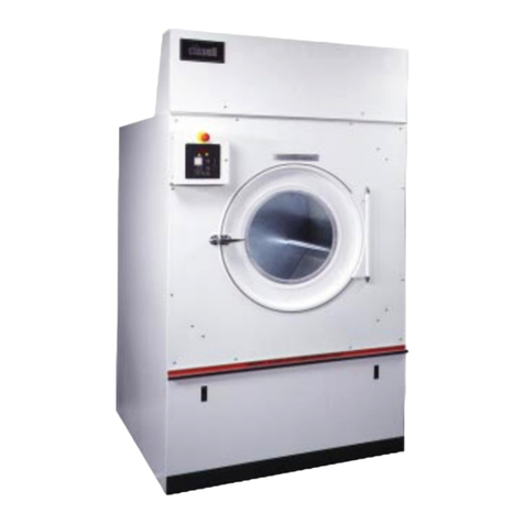
manuals.online logo
Brands
  1. Home
  2. •
  3. Brands
  4. •
  5. Cissell
  6. •
  7. Dryer
  8. •
  9. Cissell L28DRS30G User manual

Cissell L28DRS30G User manual

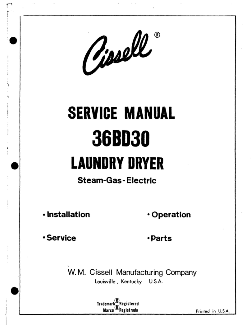
MAN471 8/96 D0528
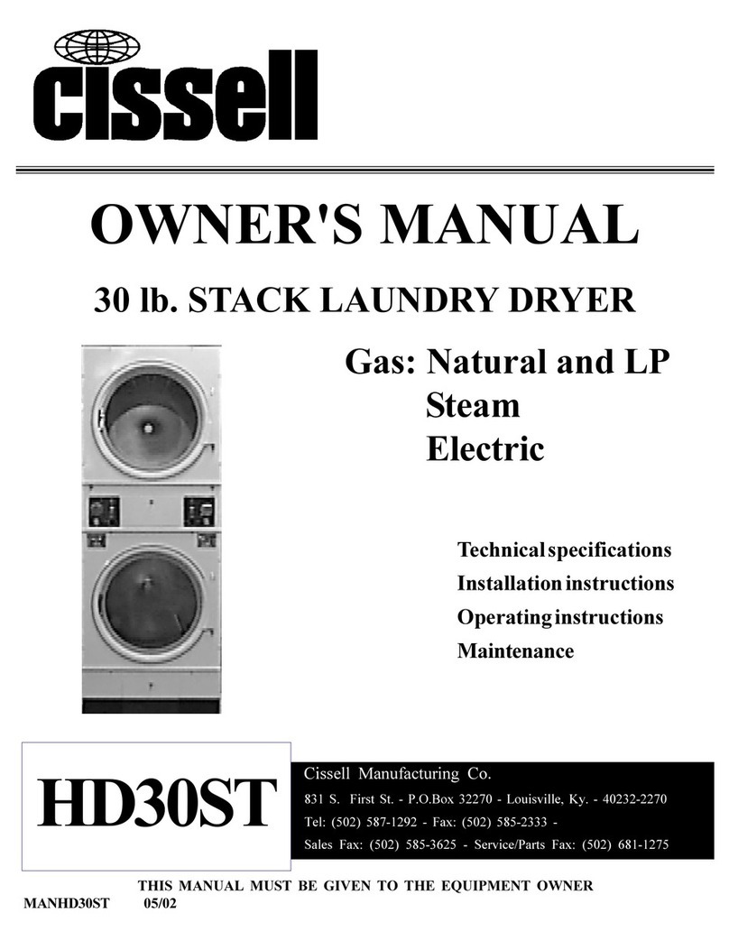
OWNER'S MANUAL
30 Lb. Stack Laundry Dryer
MODEL
GAS
L28DRS30G
THIS MANUAL MUST BE GIVEN TO THE EQUIPMENT OWNER.
MANUFACTURING COMPANY
CISSELL MANUFACTURING COMPANY
HEADQUARTERS PHONE: (502) 587-1292
831 SOUTH FIRST ST. SALES FAX: (502) 585-3625
P.O. BOX 32270 SERVICE/PARTS FAX: (502) 681-1275
LOUISVILLE, KY 40232-2270
Page 2
IMPORTANT NOTICES—PLEASE READ
For optimum efficiency and safety, we recommend that you read the Manual before operating the equipment.
Store this manual in a file or binder and keep for future reference.
WARNING: For your safety, the information in this manual must be followed
to minimize the risk of fire or explosion or to prevent property damage,
personal injury, or loss of life.
- Do not store or use gasoline or other flammable liquids or vapors in the
vicinity of this or any other appliance.
- WHAT TO DO IF YOU SMELL GAS
• Do not try to light any appliances.
• Do not touch any electrical switch; do not use any phone in your building.
• Clear the room, building, or area of all occupants.
• Immediately call your gas supplier from a neighbor's phone. Follow the
gas supplier's instructions.
• If you cannot reach the gas supplier, call the fire department.
Installation and service must be performed by a qualified installer, service
agency or the gas supplier.
WARNING: In the event the user smells gas odor, instructions on what to do must be
posted in a prominent location. This information can be obtained from the local gas
supplier.
WARNING: Wear Safety Shoes to prevent injuries.
WARNING: Purchaser must post the following notice in a prominent location:
FOR YOUR SAFETY
Do not store or use gasoline or other flammable vapors
and liquids in the vicinity of this or any other appliance.
WARNING: A clothes dryer produces combustible lint and should be exhausted
outside the building. The dryer and the area around the dryer should be kept free of
lint.
WARNING: Be safe, before servicing machine, the main power should be shut off.
Page 3
WARNING: To avoid fire hazard, do not dry articles containing foam rubber or similar
texture materials. Do not put into this dryer flammable items such as baby bed
mattresses, throw rugs,undergarments (brassieres, etc.) and other items which use
rubber as padding or backing. Rubber easily oxidizes causing excessive heat and
possible fire. These items should be air dried.
WARNING: Synthetic solvent fumes from drycleaning machines create acids when drawn
through the dryer. These fumes cause rusting of painted parts, pitting of bright or plated
parts, and completely removes the zinc from galvanized parts, such as the tumbler basket. If
drycleaning machines are in the same area as the tumbler, the tumbler's make-up air must
come from a source free of solvent fumes.
WARNING: Do not operate without guards in place.
WARNING: Check the lint trap often and clean as needed but at least a minimum of once
per day.
WARNING: Alterations to equipment may not be carried out without consulting with the
factory and only by a qualified engineer or technician. Only Cissell parts may be used.
WARNING: Remove clothes from dryer as soon as it stops. This keeps wrinkles from
setting in and reduces the possibility of spontaneous combustion.
WARNING: Be Safe - shut main electrical power and gas supply off externally before
attempting service.
WARNING: Never use drycleaning solvents, gasoline, kerosene, or other flammable liquids
in the dryer. FIRE AND EXPLOSION WILL OCCUR. NEVER PUT FABRICS
TREATED WITH THESE LIQUIDS INTO THE DRYER. NEVER USE THESE
LIQUIDS NEAR THE DRYER..
WARNING: Never let children play near or operate the dryer. Serious injury could occur if a child
should crawl inside and the dryer is turned on.
WARNING: Never tumble fiberglass materials in the dryer unless the labels say they are machine
dryable. Glass fibers break and can remain in the dryer. These fibers cause skin irritation if they become
mixed with other fabrics.
WARNING: Before operating gas ignition system - purge air from Natural Gas or Propane Gas Lines
per manufacturer’s instructions..
Page 4
CISSELL DRYER WARRANTY
The Cissell Manufacturing Company (Cissell) warrants all new equipment (and the original parts thereof)
to be free from defects in material or workmanship for a period of two (2) years from the date of sale thereof
to an original purchaser for use, except as hereinafter provided. With respect to non-durable parts normally
requiring replacement in less than two (2) years due to normal wear and tear, and with respect to all new
repair or replacement parts for Cissell equipment for which the two (2) year warranty period has expired,
or for all new repair or replacement parts for equipment other than Cissell equipment, the warranty period
is limited to ninety (90) days from date of sale. The warranty period on each new replacement part furnished
by Cissell in fulfillment of the warranty on new equipment or parts shall be for the unexpired portion of the
original warranty period on the part replaced.
With respect to electric motors, coin meters and other accessories furnished with the new equipment, but
not manufactured by Cissell, the warranty is limited to that provided by the respective manufacturer.
Cissell's total liability arising out of the manufacture and sale of new equipment and parts, whether under
the warranty or caused by Cissell's negligence or otherwise, shall be limited to Cissell repairing or replacing,
at its option, any defective equipment or part returned f.o.b. Cissell's factory, transportation prepaid, within
the applicable warranty period and found by Cissell to have been defective, and in no event shall Cissell be
liable for damages of any kind, whether for any injury to persons or property or for any special or
consequential damages. The liability of Cissell does not include furnishing (or paying for) any labor such
as that required to service, remove or install; to diagnose troubles; to adjust, remove or replace defective
equipment or a part; nor does it include any responsibility for transportation expense which is involved
therein.
The warranty of Cissell is contingent upon installation and use of its equipment under normal operating
conditions. The warranty is void on equipment or parts; that have been subjected to misuse, accident, or
negligent damage; operated under loads, pressures, speeds, electrical connections, plumbing, or conditions
other than those specified by Cissell; operated or repaired with other than genuine Cissell replacement
parts; damaged by fire, flood, vandalism, or such other causes beyond the control of Cissell; altered or
repaired in any way that effects the reliability or detracts from its performance, or; which have had the
identification plate, or serial number, altered, defaced, or removed.
No defective equipment or part may be returned to Cissell for repair or replacement without prior written
authorization from Cissell. Charges for unauthorized repairs will not be accepted or paid by Cissell.
CISSELL MAKES NO OTHER EXPRESS OR IMPLIED WARRANTY, STATUTORY OR OTHERWISE,
CONCERNING THE EQUIPMENT OR PARTS INCLUDING, WITHOUT LIMITATION, A WARRANTY
OF FITNESS FOR A PARTICULAR PURPOSE, OR A WARRANTY OF MERCHANTABILITY. THE
WARRANTIES GIVEN ABOVE ARE EXPRESSLY IN LIEU OF ALL OTHER WARRANTIES, EXPRESS
OR IMPLIED. CISSELL NEITHER ASSUMES, NOR AUTHORIZES ANY PERSON TO ASSUME FOR IT,
ANY OTHER WARRANTY OR LIABILITY IN CONNECTION WITH THE MANUFACTURE, USE OR SALE
OF ITS EQUIPMENT OR PARTS.
For warranty service, contact the Distributor from whom the Cissell equipment or part was purchased. If
the Distributor cannot be reached, contact Cissell.
IDENTIFICATION NAMEPLATE
The Identification Nameplate is located on the rear wall of the dryer. It contains the dryer serial number, product
number, model number, electrical specifications and other important data that may be needed when servicing
and ordering parts, wiring diagrams, etc. Do not remove this nameplate.
Page 5
TABLE OF CONTENTS
30 LB. STACK LAUNDRY DRYER
PAGE
Model Numbers & Company Address ...............................1
Important Notices............................................................... 2-3
Dryer Warranty....................................................................... 4
Table of Contents.................................................................... 5
Warnings, Cautionary Notes and Symbols .................. 6-7
Unpacking and General Insulation................................ 8-9
Dryer Outline Dimension (Illustration)....................10-11
Specifications...................................................................12-15
Motor List ...............................................................................16
Electrical Connections.........................................................17
Gas Piping Installation .......................................................18
Gas Service Installation......................................................19
Gas Piping Installation Instructions ...............................20
Gas Pipe Size Chart .............................................................21
Steam Piping Installation ............................................22-23
Dryer Installation with Multiple Exhaust ...............24-25
Dryer Exhausts .....................................................................26
Dryer Installation with Separate Exhaust ..............27-28
Exhaust and Venting .....................................................29-30
Rules for Safe Operation of Dryer....................................31
Energy Saving Tips ........................................................32-33
Operating Instructions.................................................. 34-36
Two Timer Model Operation Instructions................37-38
Service Savers........................................................................39
Troubleshooting...............................................................40-43
Spark Ignition System...................................................44-45
General Maintenance .................................................... 46-47
Burner Air Inlet Shutters Adjustment .....................48-49
PAGE
Replacing Bearings and Collars Instructions................50
Eccentric Locking Bearing Collars
Removal Instructions ......................................................51
Basket Alignment ...........................................................52-53
Shimming the Basket and Spider Assembly .................54
Air Switch Adjustment........................................................55
Gear Reducer Information..................................................56
Duct Work and Air Switch Assembly..............................57
Dryers with Reversing Control Timer.......................58-59
Dryer - Front Exploded View.......................................60-61
Single Motor Model - Rear View................................. 62-63
Double Motor Model - Rear View ...............................64-65
Front Panel and Door Assembly .......................................66
Bearings and Related Parts ...............................................67
Small Gear Reducer .............................................................68
Control Panel and Access Door - Single Timer .............69
Control Panel and Access Door - Two Timer .................70
Control Panel and Access Door - Coin Timer ................71
Thermostat Assembly..........................................................72
Standard Gas Bonnet ..........................................................73
Energy-Saver Gas Bonnet ..................................................74
Steam Heating Unit - Nine Section .................................75
Electric Heating Unit ..........................................................76
Electric Bonnet “UR” Model...............................................77
Electric Heating Circuit......................................................78
Reversing Control Box Assembly......................................79
Table for Ordering Overload Heaters for Overload
Relays .................................................................................80
Page 6
NOTE!
on
marche
Ein
conectado
off
arrêt
Aus
desconectado
Hot! Do Not Touch
Heib! Nicht Beruhren
Haute temperature! Ne pas toucher
Caliente! no tocar
Heet! Niet Aanraken
start
demarrage
Start
arranque de un movimiento
emission of heat in general
êmission de chaleur en general
Warmeabgabeallgemein
emisión de calor
cooling
refroidissement
Kuhlen
enfriamiento
dangerous voltage
tension dangereuse
GafahrlicheelektrischeSpannung
tension peligrosa
SYMBOLS
The following symbols are used in this manual and/or on the machine. The numbers between () refer
to the numbers on the machine surveys.
Symbol Description Part/Measurement
Page 7
rotation in two directions
rotation dans les deux sens
Drehbewigung in zwei Richtungen
movimiento rotativo en los dos sentidos
direction of rotation
sens de mouvement continu de rotation
Drehbewegung in Pfeilrichtung
movimiento giratorio o rotatorio
en el sentido de la flecha
End of Cycle
caution
attention
Achtung
atencion; precaucion
SYMBOLS
The following symbols are used in this manual and/or on the machine. The numbers between () refer
to the numbers on the machine surveys.
Symbol Description Part/Measurement
Page 8
STACK DRYER SPECIFICATIONS
SPECIFICATIONS
Tumbler Capacity (Dry Weight) 30 lbs.
Tumbler Diameter 27”
Tumbler Depth 29”
Approx. Weight (Uncrated) 800 Lbs.
Approx. Weight (Shipping Weight) 850 Lbs.
Motor (HP) 1/2
Air Flow (Per Pocket) 450 CFM
Heat Input (Per Pocket) 75,000 BTU/H
Exhaust Diameter 6”
Door Opening 22-5/8”
Electrical Specifications 115/208/230v
50/60Hz - 1 phase
Manufacturer reserves the right to make changes
in specifications without notice or obligation.
Page 9
PLANNING FOR INSTALLATION
Cissell Manufacturing Co. provides quality appliances that are easy to
install, operate and service. Each dryer is delivered complete and
ready for connection to external vent ducts, power and gas lines.
Plan for the installation of your dryer before it arrives. This will save
you time and will assist your contractors at installation. Check to see
if a permit is required. A preinstallation check list should include:
A sketch of the dryer room with dimensions. Show the dryer
location - place the dryers next to an outside wall if possible.
Allow space for rear servicing and periodic inspection behind
the dryers - (3) feet minimum is recommended for ease of
servicing.
Do not install dryer in a corrosive or contaminated atmosphere
or near combustible materials. Make sure circulating air
requirements are adhered to.
Do not install or store dryer in an area where it will be exposed
to water and/or weather.
Show walls and partitions.
Show location and size of venting duct outlet.
Show the location of electrical power.
Specify the location of the gas supply.
Installation should be on a sound, carpetless and level floor
capable of supporting dryer weights. Check your local building
codes.
Calculate the size of vents required to supply the dryer room
with outside air (MAKE-UP AIR). Refer to the ADEQUATE
AIR SUPPLY section of this manual.
Optional: An electrical outlet box for connecting a vacuum or
other tools and rear lighting for better visibility during
servicing.
The installation of the dryer should be performed by qualified licensed
proferssionals in accordance with local building codes and local, state
and federal standards. Warranty is void unless dryer is installed
according to instructions in this manual. All dryer installations by the
owner or contractors must conform to all or part of the following
regulations:
National Fuel Gas Code - ANSI #Z223.1 (latest edition).
National Electric Code - ANSI/NFPA #70 (latest edition).
National Electric Code - USAS-C1 (branch circuit grounding
conductors to metallic boxes)
CAN 1-B149.1 & 2 - Installation codes for gas burning appliances.
CSA C22.1 Canadian Electrical Code Part 1.
PLANNING FOR
INSTALLATION
CODES &
STANDARDS
United States
Canada
Page 10
PLANNING FOR INSTALLATION (CONT.)
The installation of a dryer is not complex. The dryer requires make-up
air, gas for drying heat, electrical power, and air exhaust ducts.
For safety, all installation and testing must conform to the CODES
AND STANDARDS section of this manual.
The stack dryer may be installed in various configuration including
free standing against a wall or recessed into a partition wall or room
(as illustrated). It is recommended that adjacent materials be
noncombustible. As illustrated, clearances to combustible construction
material are minimum.
CONSTRUCTION
CLEARANCE
Note A
Note B
Other
When dryer is installed flush with and protruding through a wall, the
first 4” may contact combustible construction. From the point back, top
clearance must be 6” and side clearance 1”.
Rear clearance is 12” minimum - (36” is recommended for ease of
installation, maintenance and service).
2” clearance from exhaust ducting.
12” minimum clearance from top of dryer to sprinkler system.
Page 11
PLANNING FOR INSTALLATION (CONT.)
To operate safety and efficiently, a dryer must intake clean dry air,
pass it through the dryer and then exhaust it outside of the building.
The air taken into the dryer is called MAKE-UP AIR.
A dryer can quickly deplete available MAKE-UP AIR in a sealed
insulated room, consequently vents to the outside of the building are
required. Vents are usually openings in a wall covered with louvers.
Each L28DRS 30G dryer requires 2 square feet of unrestricted outdoor
MAKE-UP AIR to operate efficiently.
ADEQUATE AIR
SUPPLY
Page 12
UNPACKING AND LEVELING
Your new dryer should be kept in a clean environment. All major
construction (i.e. walls, partitions, enclosures) should be substantially
complete before unpacking. The dryer is delivered bolted to a skid and
covered with a polyethylene protective cover.
Inspect for damage before unpacking. Immediately report any
apparent damage to the carrier before you sign the receipt
(document the damage on the trucker’s receipt).
If damage is found after the carrier has departed, call the
freight terminal immediately and request an INSPECTION
AND FREIGHT CLAIM FORM. Save all packing material.
Unpack the dryer.
Open the upper dryer door and remove the envelope containing
keys, leveling pads and INSTALLATION & OPERATION
MANUAL.
Unlock and remove the lower lint compartment door.
Unscrew the (4) crate bolts holding dryer on the skid - save (2)
crate bolts for leveling.
Slide dryer off the skid.
Note that external connections for electric and gas are made at
the top rear of the dryer. The exhaust collars for vent ducts are
located on the back for both tumblers.
Remove shipping blocks located between tumbler and front
door panel.
All electrical, gas and vent ducts should be in place and ready for hook-
up before the dryer is moved into position.
UNPACKING
LEVELING
Remove (2) foot pads from
envelope (shipped in upper
tumbler door).
Screw (2) crate bolts thru
rear base of dryer and into
foot pads (refer to
illustration). Front foot
pads are factory installed.
Level dryer from side to
side.
Tilt dryer back 2º - 3º
Page 13
ELECTRICAL AND GAS INSTALLATION
A licensed electrical contractor should install the electrical service for
the dryer. Personal injury/dryer failure may result if not installed
according to codes and standards.
Remove the back guard and locate the wiring diagram on left
side panel.
Verify that the voltage, frequency and phase of the electrical
service is the same as specified on the dryer data label.
Install each dryer on a separate circuit. Check for polarity.
Use copper wire - not aluminum. Provide a separate ground
wire. Each circuit should include a circuit breaker of the
correct amperage. Some building codes may require a ground
fault interrupter (GFI) breaker.
Connect the electrical service to the outlet box at the rear top of
each dryer. Add a strain relief and grommet where the service
enters the outlet box. A wiring diagram is provided with each
dryer.
Ground the dryer. The separate ground wire must be installed
in accordance with best commercial practice and in compliance
with local building codes and local, state and federal standards.
A licensed plumber should install the plumbing service for the dryer.
Personal injury/dryer failure may result in not installed according to
codes and standards.
Verify that the gas service corresponds to that specified on the dryer
data label. Unless special ordered from the factory, all data is based
upon dryer installation under 2,000 feet elevation.
Install 1/2” nominal pipe (except butane or propane) from the
service enterance to each dryer. Smaller diameter pipe will
result in ignition problems, slow drying, increased use of
energy and may create a safety problem.
Install a MAIN GAS SHUT-OFF valve that turns off the gas
supply to the dryer.
Connect gas line to dryer gas pipe at top of dryer.
Install a continuous loop manifold. The size and length of gas
supply line, number of gas fittings, pipe line friction, gas
manifold pressure and gas/air mixture can be determined by
your plumber or gas company.
Install a MAIN GAS SHUT-OFF valve that turns off the gas
supply to the dryer.
Connect gas line to dryer gas pipe at top of dryer.
ELECTRICAL
GAS
Single dryer
Multiple dryers
Page 14
TYPICAL GAS INSTALLATION
Page 15
GAS DATA
TYPE OF GAS
NATURAL LIQUID PROPANE (L.P.)
Manifold pressure 3.5 inches W.C. 11 inches W.C.
In-line pressure (W.C.) 6.0 inches to 12.0 inches 11 inches W.C.
Orifice size (D.M.S.) #20 3/32”
The dryer must be isolated from the gas supply piping system by
closing its individual manual shutoff valve during any pressure testing
of the gas supply piping system at test pressure equal to less than 1/2
PSIG (3.5 KPA).
Failure to comply with this could cause fire or explosion and/or dryer
damage.
Test each gas connection for leaks by brushing on a soapy water or
detergent solution. Never test for leaks with an open flame.
GAS TESTING
Gas outlet size 1/2” N.P.T.
BTUH input (each tumbler) 75,000
BTUH input (per dryer) 150,000
Manifold pressure measured at gas valve pressure tap when gas
valve is on. Measured in inches of water column.
Drill Manufacturers Standard (D.M.S.) is equivalent to standard
twist drill.
Water column (W.C.) is in inches.
Important
The dryer is set up for natural gas. If Liquid Petroleum (L.P.) Gas is to be
used, a kit with instructions is shipped in the basket with the dryer.
Page 16
VENTING AND EXHAUSTING
A licensed contractor should install the dryer vent ducts. Duct work
not properly designed and installed or which does not meet codes and
standards can be a potential source of fire, personal injury and dryer
failure.
Each dryer tumbler must be exhausted outside the building via a
ducting system. Basically there are (4) categories:
Individual duct - Dual duct - Main Connector duct - Custom duct
Improperly sized ducts will create excessice back pressure which
results in slow drying, increase in energy usage, overheating of dryer
and possible dryer damage.
Do not obstruct the flow of combustion and ventilation air.
VENT DUCTS
Shape of duct is not critical if cross sectional area is
maintained.
Use rust resistant duct material.
Inside of ducts should be smooth with no sheet metal screws
protruding.
Overlap all joints.
Tape all joints to avoid air loss and to avoid condensation.
Install several clean-out and inspection doors.
Do not exceed 20’ of duct work.
Do not use 90º turns. Use 30º or 45º instead.
Ducts should have 2” of clearance (all around) when they go
through a wall.
Insulate ducts passing through walls or cold areas.
Horizontal ducts exiting a building should terminate with a 90º
elbow bent downward. Do not put screening or cap over end of
duct. Minimum clearance from the end of 90º elbow to ground
should be 2x duct diameter.
Vertical ducts exiting through a roof should terminate with a
180º turn downward. Do not put screening or cap over end of
duct. Minimum clearance from the end of 180º elbow to roof
level should be 2x duct diameter.
Do not vent into enclosed spaces - i.e. an attic. Venting must
be to the outdoors.
VENTING &
EXHAUSTING
Design Guides
Page 17
MULTIPLE VENTED INSTALLATION
Whenever possible, each stack dryer tumbler should have an
individual short straight exhaust duct.
Whenever possible, each dryer tumbler in multiple installations
should have individual short straight exhaust ducts.
If an individual or dual duct is not possible, install a long
tapered main connector duct. A duct exceeding 20’ should be
a custom duct designed by a professional Heating and Air
Conditioner (HVAC) contractor.
Individual tumbler ducts enter the main connector duct at a 45º
angle in the direction of exhaust air flow.
The diameter of the main connector duct progressively
increases as more dryers are added. (refer to illustration).
Back pressure of ducting system should not exceed 0.3 inch water
column when all dryers are operating. Use a manometer for tests.
More detailed ducting information can be obtained directly from your
Heating and Air Conditioning (HVAC) contractor or dealer.
Single dryer
Multiple dryers
Testing
Multiple vents
Page 18
PREOPERATIONAL TESTING
Carefully review each item in the Installation & Operation Manual.
Check the Codes & Standards section of the manual.
Dryer installation must meet or exceed all codes and standards.
Check the room venting. Each dryer must have sufficent
MAKE-UP AIR.
Read and follow all caution, warning and direction labels
attached to the dryer.
Check incoming electrical power - power must be identical to
dryer data label.
Check gas supply - supply must be identical to dryer data label.
Check that all bolts, nuts, screws, terminals and fittings are
secure.
Check all safety covers and electric box covers - they must be
installed.
Check the control panel door and lint compartment doors - they
should be closed and locked.
Manually rotate the dryer tumblers and check for interference.
Each dryer is inspected, tested and operated at the factory before
shipment. Occasionally, in transit, a dryer is subjected to excessive
vibration and shock. After installation, minor adjustments may be
necessary.
Open all gas shut offs and gas valves.
Initially load each tumbler with clean rags (removes any excess
oil remaining from the manufacturing process).
Close dryer door (on tumbler under test).
Turn on all electric power to the dryer.
INSTALLATION
CHECK
INITIAL
OPERATION TEST
Page 19
OPERATING INSTRUCTIONS - COMPUTERIZED MODELS
For “Computerized” models, the amount of dry time will appear on the
digital display. Maximum time is 99 minutes. Additional coins may be
vended any time during the cycle.
Turn Temperature Fabric Selector to desired setting. “LOW” is for
delicate, sheer, and easy dry fabrics. 130° - 140°F exhaust tempera-
ture. “MEDIUM” is for synthetics and permanent press fabrics. 155° -
165°F exhaust temperature. “HIGH” is for cottons, linens, and heavy
fabrics. 170° - 180°F exhaust temperature.
Press “PUSH TO START” button until dryer is running.
1. Digital Display will count down time remaining in cycle.
2. The fan motor and basket will revolve.
3. The heat source will be energized.
4. The heated air will mix with the wet clothes and evaporate the
moisture.
5. The thermostats will operate at a safe temperature.
6. The heat will shut off and the cooling cycle will begin.
If the tumbler door is opened during the drying cycle, the fan and heat
will shut off. Press “PUSH TO START” button to resume cycle.
This dryer is designed for a capacity maximum load. Overloading it will
result in longer drying time and damp spots on some of the load.
Maximum operating efficiency depends on proper air flow. The lint
screen must be kept clean daily to insure proper circulation of air
throughout the dryer.
This commercial dryer has keys for the lint door and access door to
burners and controls. This is for the safety of the user.
Page 20
SETTING TIME ON “COMPUTERIZED COIN METER”
Setting Time on
“Computerized”
Coin Meter”
1. This dryer is equipped with 2 separate DIP switch banks for setting
drying time. One is for 10¢, one for 25¢. This model dryer is
equipped with a single slot 25¢ coin meter.
2. Each DIP switch bank consists of 4 small switches each with a
specified amount of time (minutes), as shown:
“Off” (down) position equals 0 minutes.
3. To set the time on the 25¢ DIP: Simply set the appropriate switch
to the “on” (up) position to total the desired time. There are 3 min.
already built in the 25¢ DIP. Subtract 3 min. from your desired
total time, and set the switches to equal the remainder.
Example: 25¢ for 15 min.
15 min. (desired total time)
- 3 min. (“built-in” time)
12 min. (set switches for remainder)
DIP Switch Banks are located here

Other Cissell Dryer manuals

Cissell L50CD42G User manual

Cissell

Cissell L50CD42G User manual

Cissell L36TD30ME User manual

Cissell

Cissell L36TD30ME User manual

Cissell 70C User manual

Cissell

Cissell 70C User manual

Cissell L50CD42G User manual

Cissell

Cissell L50CD42G User manual

Cissell L36URD36E User manual

Cissell

Cissell L36URD36E User manual

Cissell HD190 User manual

Cissell

Cissell HD190 User manual

Cissell L125URDG C125G User manual

Cissell

Cissell L125URDG C125G User manual

Cissell MANHD75.1 User manual

Cissell

Cissell MANHD75.1 User manual

Cissell L44CD42G User manual

Cissell

Cissell L44CD42G User manual

Cissell ACDCMAN407 User manual

Cissell

Cissell ACDCMAN407 User manual

Cissell L28DPS30G User manual

Cissell

Cissell L28DPS30G User manual

Cissell 28BS30 User manual

Cissell

Cissell 28BS30 User manual

Cissell L28US30G User manual

Cissell

Cissell L28US30G User manual

Cissell DRYSETS User manual

Cissell

Cissell DRYSETS User manual

Cissell L36USS36G User manual

Cissell

Cissell L36USS36G User manual

Cissell HD175 User manual

Cissell

Cissell HD175 User manual

Cissell 50LB PARTS User manual

Cissell

Cissell 50LB PARTS User manual

Cissell 75LB PARTS User manual

Cissell

Cissell 75LB PARTS User manual

Cissell L36USS36G User manual

Cissell

Cissell L36USS36G User manual

Cissell MAN2075 User manual

Cissell

Cissell MAN2075 User manual

Cissell HD125 User manual

Cissell

Cissell HD125 User manual

Cissell MANHD150 User manual

Cissell

Cissell MANHD150 User manual

Cissell MANHD170 User manual

Cissell

Cissell MANHD170 User manual

Cissell HD110 User manual

Cissell

Cissell HD110 User manual

Popular Dryer manuals by other brands

Electrolux SEQ7000FS0 Use & care guide

Electrolux

Electrolux SEQ7000FS0 Use & care guide

Maytag MEDX600XW Use and care guide

Maytag

Maytag MEDX600XW Use and care guide

Ansonic SAC137 manual

Ansonic

Ansonic SAC137 manual

Bosch WTL 6301 Instruction manual and installation instructions

Bosch

Bosch WTL 6301 Instruction manual and installation instructions

Kenmore 796.9002 Series Use & care guide and installation instructions

Kenmore

Kenmore 796.9002 Series Use & care guide and installation instructions

Speed Queen VENDED ST050 Brochure & specs

Speed Queen

Speed Queen VENDED ST050 Brochure & specs

Zanussi THE8050 user manual

Zanussi

Zanussi THE8050 user manual

Amana NGD5700B Specifications

Amana

Amana NGD5700B Specifications

Maytag MD-21 user guide

Maytag

Maytag MD-21 user guide

AEG LAVATHERM 743 U operating instructions

AEG

AEG LAVATHERM 743 U operating instructions

Frigidaire CFRE5714KW0 Use & care guide

Frigidaire

Frigidaire CFRE5714KW0 Use & care guide

Maytag MGD7100D manual

Maytag

Maytag MGD7100D manual

Maytag 4KMEDC100 Use and care guide

Maytag

Maytag 4KMEDC100 Use and care guide

SUPREME Master Air II BA404 installation guide

SUPREME

SUPREME Master Air II BA404 installation guide

AGI NECO D1660 Operator's manual

AGI

AGI NECO D1660 Operator's manual

Samsung DV210A Series user manual

Samsung

Samsung DV210A Series user manual

ADC ML-30V installation manual

ADC

ADC ML-30V installation manual

GE DCVH640EJ Dimensions and installation information

GE

GE DCVH640EJ Dimensions and installation information

manuals.online logo
manuals.online logoBrands
  • About & Mission
  • Contact us
  • Privacy Policy
  • Terms and Conditions

Copyright 2025 Manuals.Online. All Rights Reserved.