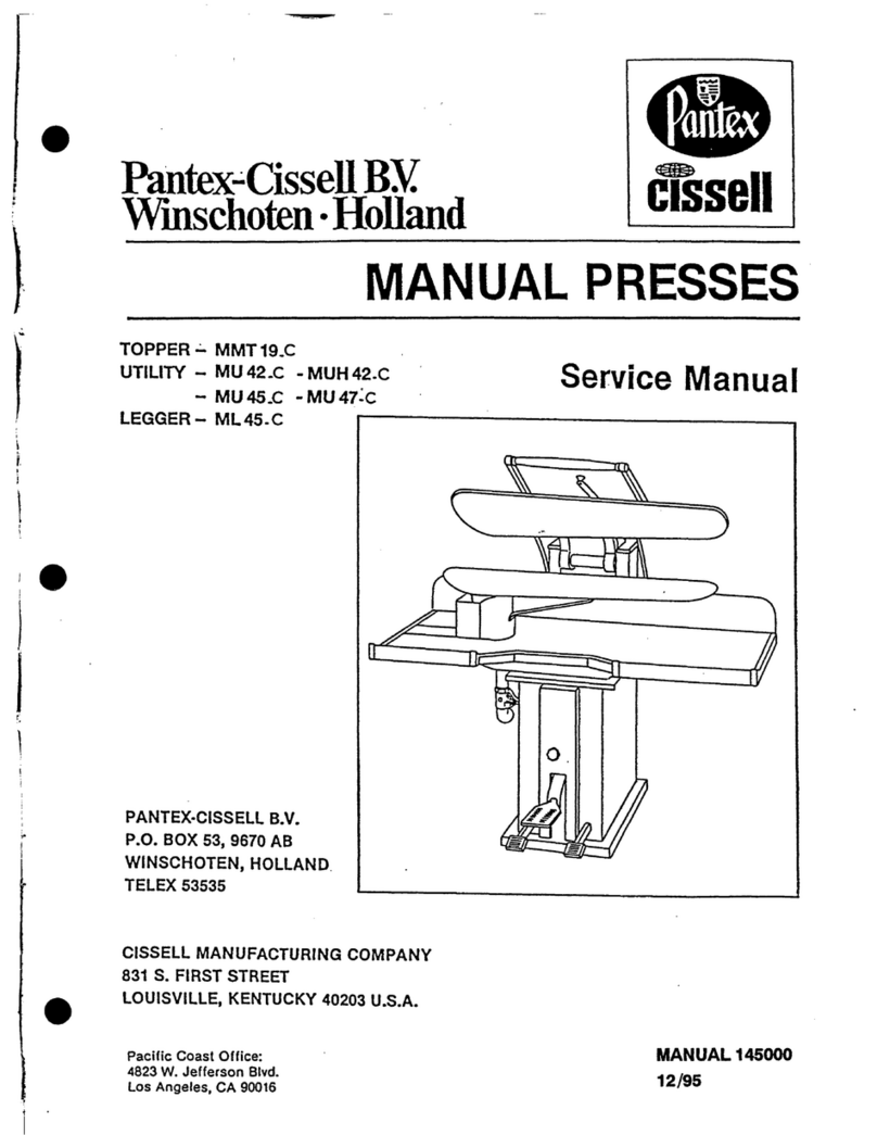
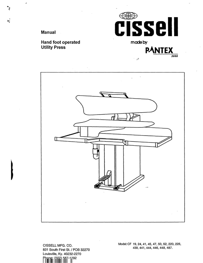
Cissell MAN65 User manual

Page 1Page 1
Page 1Page 1
Page 1
MAN65 4/05
OWNER’S MANUALOWNER’S MANUAL
OWNER’S MANUAL
FinishingFinishing
FinishingFinishing
Finishing
CabinetCabinet
CabinetCabinet
Cabinet
Model MR3FCModel MR3FC
Model MR3FC
THIS MANUAL MUST BE GIVEN TO THE EQUIPMENT OWNER.THIS MANUAL MUST BE GIVEN TO THE EQUIPMENT OWNER.
THIS MANUAL MUST BE GIVEN TO THE EQUIPMENT OWNER.
CISSELL MANUFACTURING COMPANYCISSELL MANUFACTURING COMPANY
CISSELL MANUFACTURING COMPANY
HEADQUARTERSHEADQUARTERS
HEADQUARTERS PHONE:(502)587-1292
831SOUTHFIRSTST. SALESFAX:(502)585-3625
P.O.BOX32270 SERVICE/PARTSFAX: (502)681-1275
LOUISVILLE,KY 40232-2270

Page 2Page 2
Page 2Page 2
Page 2
WARRANTYWARRANTY
WARRANTYWARRANTY
WARRANTY
TheCissellManufacturingCompany(Cissell)warrantsallnewequipment(andtheoriginalpartsthereof)
tobefreefromdefectsinmaterialorworkmanshipforaperiodofone(1)yearfromthedateofsalethereof
toanoriginalpurchaserforuse,exceptashereinafterprovided.Withrespecttonon-durablepartsnormally
requiringreplacementinlessthanone(1)yearduetonormalwearandtear,including,butnotlimitedto,
clothgoods,valvediscs,hoses,andironcords,andwithrespecttoallnewrepairorreplacementpartsfor
Cissell equipment for which the one (1) year warranty period has expired, or for all new repair or
replacementpartsforequipmentotherthanCissellequipment,thewarrantyperiodislimitedtoninety(90)
daysfromdateofsale.ThewarrantyperiodoneachnewreplacementpartfurnishedbyCissellinfulfillment
ofthewarrantyonnewequipmentorpartsshallbefortheunexpiredportionoftheoriginalwarrantyperiod
onthepartreplaced.
Withrespecttoelectricmotors,coinmetersandotheraccessoriesfurnishedwiththenewequipment,but
not manufactured by Cissell, the warranty is limited to that provided by the respective manufacturer.
Cissell'stotalliabilityarisingoutofthemanufactureandsaleofnewequipmentandparts,whetherunder
thewarrantyorcausedbyCissell'snegligenceorotherwise,shallbelimitedtoCissellrepairingorreplacing,
atitsoption,anydefectiveequipmentorpartreturnedf.o.b.Cissell'sfactory,transportationprepaid,within
theapplicablewarrantyperiodandfoundbyCisselltohavebeendefective,andinnoeventshallCissellbe
liable for damages of any kind, whether for any injury to persons or property or for any special or
consequentialdamages.TheliabilityofCisselldoesnotincludefurnishing(orpayingfor)anylaborsuch
asthatrequiredtoservice,removeorinstall;todiagnosetroubles;toadjust,removeorreplacedefective
equipmentorapart;nordoesitincludeanyresponsibilityfortransportationexpensewhichisinvolved
therein.
ThewarrantyofCissellis contingentuponinstallationanduseofitsequipmentunder normaloperating
conditions.Thewarrantyisvoidonequipmentorparts;thathavebeensubjectedtomisuse,accident,or
negligentdamage;operatedunderloads,pressures,speeds,electricalconnections,plumbing,orconditions
other than those specified by Cissell; operated or repaired with other than genuine Cissell replacement
parts; damaged by fire, flood, vandalism, or such other causes beyond the control of Cissell; altered or
repaired in any way that effects the reliability or detracts from its performance, or; which have had the
identificationplate,orserialnumber,altered,defaced,orremoved.
NodefectiveequipmentorpartmaybereturnedtoCissellforrepairorreplacementwithoutpriorwritten
authorizationfromCissell.ChargesforunauthorizedrepairswillnotbeacceptedorpaidbyCissell.
CISSELL MAKES NO OTHER EXPRESS OR IMPLIED WARRANTY, STATUTORY OR OTHERWISE,
CONCERNING THE EQUIPMENT OR PARTS INCLUDING, WITHOUT LIMITATION, A WARRANTY
OF FITNESS FOR A PARTICULAR PURPOSE, OR A WARRANTY OF MERCHANTABILITY. THE
WARRANTIES GIVEN ABOVE ARE EXPRESSLY IN LIEU OF ALL OTHER WARRANTIES, EXPRESS
OR IMPLIED. CISSELL NEITHER ASSUMES, NOR AUTHORIZES ANY PERSON TO ASSUME FOR IT,
ANY OTHER WARRANTY OR LIABILITY IN CONNECTION WITH THE MANUFACTURE, USE OR SALE
OF ITS EQUIPMENT OR PARTS.
Forwarrantyservice,contacttheDistributorfromwhomtheCissellequipmentorpartwaspurchased.If
theDistributorcannotbereached,contactCissell.
Page 3Page 3
Page 3Page 3
Page 3
TABLE OF CONTENTSTABLE OF CONTENTS
TABLE OF CONTENTS
Warranty ...............................................................................2
Specifications .......................................................................3
Steam Piping Recommendations ......................................... 4-5
Operating Instructions ..........................................................6
Trouble Shooting Chart .........................................................7
Parts Sheets ....................................................................... 8-13
MR3FC FINISHING CABINETMR3FC FINISHING CABINET
MR3FC FINISHING CABINET
SPECIFICATIONSSPECIFICATIONS
SPECIFICATIONS
Electrical....................................................4 amps, 220V/50 Hz/1 Ph.;
or 8 amps, 115V/60 Hz/1 Ph.
Exhaust Duct .............................................4” diameter with Adjustable damper for
variable stack lengths
Steam Supply Line .....................................1/2” NPT
Steam Return Line......................................1/2” NPT
Boiler Horsepower .....................................60-100 P.S.I.G.
Floor Space................................................34” deep x 41 1/2” wide x 83” high
(86 cm x 105 cm x 211 cm)
Net Weight (approximate) ..........................560 lbs. (254 kg.)
Domestic Shipping Weight (approximate)...615 lbs. (279 kg.)
Export Shipping Dimensions (approximate)45” x 38” x 86” (114 cm x 97 cm x 218
cm)
Export Shipping Weight (approximate) .......615 lbs. (254 kg.) (container shipment)
875 lbs. (397 kg.) (wood box)
Cubic Feet Export Crating ..........................85 cu. ft.

Page 4Page 4
Page 4Page 4
Page 4
STEAM PIPING RECOMMENDATIONSSTEAM PIPING RECOMMENDATIONS
STEAM PIPING RECOMMENDATIONS
IMPORTANT: INSTALL STEAM PIPING IN ACCORDANCE WITH ALL LOCAL
REGULATIONS AND REQUIREMENTS.
1. Set and level Cabinet in position. Machine should be level to assure proper steam
and circulation.
2. To prevent condensate draining from headers to Cabinet, piping should have a
minimum riser 12” above each respective header as illustrated on next page. Do
not make steam connection to header with a horizontal or downwardly facing tee or
elbow.
3. Whenever possible, horizontal runs or steam lines must drain, by gravity, to
respective steam header. Water pockets, or an improperly drained steam header
will provide wet steam causing improper operation of Cabinet. If pockets or im-
proper drainage cannot be eliminated, install a by-pass trap to drain condensate
from the low point in the steam supply header to the return.
4. In both the steam supply and steam return line, it is recommended that each have a
1/2” union and 1/2” globe valve. This will enable you to disconnect the steam
connections and service the Cabinet while your plant is in operation.
5. Before connecting trap and check valve to Cabinet, open globe valve in steam
supply line and allow steam to flow through Cabinet to flush out any dirt and scale
from Cabinet. This will assure proper operation of trap when connected. If steam
is dirty, it will be adviseable to install a filter or blow down line ahead of cabinet.
6. After flushing system, install trap and strainer as illustrated. Inspect trap and
strainer carefully for inlet and outlet markings and install according to
manufacturers instructions. If steam is gravity returned to boiler, omit trap but
install check valve in return line near Cabinet.
7. When cabinet is on end of a line of equipment extend headers at least 4 ft. beyond
Cabinet. Install globe valve, union, check valve and by-pass at end of line. If steam
is gravity returned to boiler, omit trap.
8. Insulate steam supply and return lines for safety of operator while servicing
Cabinet.
9. Keep Cabinet in good working condition. Repair or replace any worn or defective
parts.
The interior of the tunnel will turn white as the protective zinc oxide coating forms.
Do not try to remove this coating.
Do remove lint, dust, and boiler compound or red dust which is entrained by the steam.
Touch-up scratches and chips in the paint. A good car wax will extend life of the
painted surface.

Page 5Page 5
Page 5Page 5
Page 5

Page 6Page 6
Page 6Page 6
Page 6
OPERATING INSTRUCTIONSOPERATING INSTRUCTIONS
OPERATING INSTRUCTIONS
FOR CISSELL MOIST-RITE CABINETS AND TUNNELSFOR CISSELL MOIST-RITE CABINETS AND TUNNELS
FOR CISSELL MOIST-RITE CABINETS AND TUNNELS
Forward - The Moist-Rite Finishing Cabinets and Finishing Tunnels are designed to restore the
finish on most garments. It does an exceptional job on most wool, wool blends, synthetic
blends, double and bonded knits and in general imparts a better finish on the quality gar-
ments. The machine will not completely finish all garments but it will impart some finish to
nearly all garments except those made of untreated cotton or linen, some blends of rayon and
some of the permanent press garments which have lost their resin treatment.
The steam cabinet or tunnel employs three basic principles. First, it introduces moisture to the
garment during the steaming cycle (analogous to sprinkling clothes for ironing); second, it
allows the moisture to penetrate into the garment during the conditioning cycle (analogous to
letting the sprinkled clothes stand overnight); and third, it drys the garment with pressure and
heat during the drying cycle by inflating the garment with hot air (analogous to ironing a
garment).
Because of the variables in the type and weight of garments and steam pressure used, it will be
necessary to establish your own cycle time for steaming, conditioning and drying. The shorter
the cycle times, the greater will be the number of garments finished in a given time. For
convenience, it may be desirable to set the machine for longer cycle times to include all differ-
ent garments. Longer cycle times will not be harmful to the garments.
No more than a week should be required to select your own optimum settings.
Steaming Time - For the shortest and surest moisture penetration, the moist steam setting
should be selected which allows hot water to be injected along with the dry steam. The amount
of water injected is dependent on the setting of the needle valve which is located near the
condensate solenoid valve (see manual), usually this will be set at 1/8 to 1/4 turn open. For
best results open to the maximum setting that gives a finished garment with no beads of water
on the lower hem of garments at the end of the drying cycle. A setting of 15 to 60 seconds for
steaming should be suitable for most garments. Experimentation, however, may result in more
or less time.
Conditioning Time - This is a setting which should be increased for heavier garments to allow
more time for the moisture to penetrate the fabric of the garment. Again 15 to 60 seconds
should be suitable. Experiment and then check the end results on the finished garments. On
the tunnel models, the moisture penetration can be improved by the steam and air selector
which drives the moisture inside the garment and is especially effective on garment linings.
Drying Time - This setting will depend on the weight of the garment fabric, type of fabric,
length of steaming cycle and length of conditioning cycle. Set this cycle long enough to insure a
dry garment, perhaps 30 to 90 seconds. Again experimentation is necessary to determine best
results.
Appearance - Good results have been achieved when the garment has a smooth appearance, is
free of wrinkles, is dry and there is a sheen or lustre to the fabric. Remember - a good finish
job starts with enough moisture, if in doubt, increase the steaming time and/or the needle
valve setting.

Page 7Page 7
Page 7Page 7
Page 7
CAUSECAUSE
CAUSECAUSE
CAUSE
Electric power off
Loose or broken wires to start
button
Defective start switch
Defective timer cam or drive
Advance button is defective or
depressed
Defective wiring
Start button stuck or defective
Defective wiring
Defective timer
Defective wiring or short
circuit
Potentiometer knob incorrectly
set
Loose or broken wires
Defective timer
Water metering valve turned
off
Water solenoid valve defective
Water solenoid valve not
electrically energized
Defective timer
Water line clogged
Steam line clogged
Steam solenoid valve defective
Steam solenoid valve not
electrically energized
Defective timer
Moisture metering valve open
toowide
Steam trap not functioning
properly
Condensate line strainer
clogged
Motor defective
Timer defective
Relay defective
Wiring defective
Blower wheel loose
Defective blower wheel
Foreign object in blower wheel
Exhaust damper closed
Blower not operating
Exhaust duct clogged
Steam cycle too long
REMEDYREMEDY
REMEDYREMEDY
REMEDY
Turn power on.
Inspect wiring and repair.
Check and replace if needed.
Inspect wiring and terminals.
Check and replace if needed.
Inspect wiring and terminals.
Check and replace if needed.
Inspect wiring and terminals.
Reset and tighten.
Inspect wiring and terminals.
Check and replace if needed.
Open1/4” to 1/2” turn.
Check and replace if needed.
Check wiring and terminals.
Check and replace if needed.
Clean clogged part.
Clean clogged part.
Check and replace if needed.
Inspect wiring and check valve.
Check and replace if needed.
Open1/8” to 1/4” turn.
Check and clean or replace.
Check and replace if needed.
Tighten set screw.
Check and replace if needed.
Remove foreign object.
Check and repair.
Check and replace.
Clean out duct.
Check and reset.
PROBLEMPROBLEM
PROBLEMPROBLEM
PROBLEM
Machine will not operate
Machine advances to “OFF”
position when started
Machine re-cycles continuously
Timing too short on one of the
three settings
Timing too long on one of the
three settings or will not
proceed through cycles
No water fog at steam jet,
steam too dry
No steam at jet
Steam too wet; excessive
moisture in cabinet
Blower will not operate
Excessive noise during drying
and steaming cycle
Excessive loss of steam or heat
around door opening

Page 8Page 8
Page 8Page 8
Page 8
36

Page 9Page 9
Page 9Page 9
Page 9
FINISHING CABINETFINISHING CABINET
FINISHING CABINET
Ref.Ref.
Ref.Ref.
Ref. PartPart
PartPart
Part
No.No.
No.No.
No. No.No.
No.No.
No. DescriptionDescription
DescriptionDescription
Description
1 SC489 Upper Side Access Panel
2 SC487 Lower Side Access Panel
3 SC420 Motor Mount
4 MTR88 Motor - 1/2H 110-120/220-240
50/60/1 Ph.
5 SC6 Blower Housing
6 SC790 Blower Wheel
7 SC555 Door Stop
8 SC554 Seal Bracket
9 SC553 Lower Door Seal
10 SC503 Control Panel Cover
11 TUB1867 Lock & Key
12 FB405 Cissell Nameplate
13 SC486 Roller Carriage Rod
14 FG444 Yoke
15 SF48 Clevis Pin
16 SC484 Roller Carriage Stop
17 SC478 Hanger Bar Support
18 SC482 Hanger Bar
19 SC485 Door Angle
20 SC950 Roller Carriage
21 C553 Roller (4 req’d)
22 C773 Shoulder Bolt for C553
23 SC472 Vibrator Motor
24 SC473 Base
25 SC153 Spacer
26 SC462 Door Handle
27 SC586 Left Door Assembly
28 SC587 Right Door Assembly
29 SC558 Door Bushing
30 SC461 Hinge Plate
31 SC474 Operating Nameplate
32 SC508 Damper Assembly
33 SC453 Blower Enclosure Top
34 SC406 Trim
35 SC483 Carriage Track (2 req’d)
36 Sc976 Inlet Ring
TU2844 JWC-2 Key only for TUB1867
SC855 Roller Carriage Assy. Complete
includes 16, 17, 20, 21 & 22

Page 10Page 10
Page 10Page 10
Page 10

Page 11Page 11
Page 11Page 11
Page 11
Ref.Ref.
Ref.Ref.
Ref. PartPart
PartPart
Part
No.No.
No.No.
No. No.No.
No.No.
No. DescriptionDescription
DescriptionDescription
Description
1 SC552 Coil Hold Down Bracket
2 SC158 Cross Over Tube Assembly
3 SC611 Steam Jet Bracket
4 SC108 Mixing Jet Assembly
5 OP297 1/8 Pipe x 1/4 Tube St. Connector
6 SC572 Mixing Jet Tube (Water)
7 SC571 Mixing Jet Tube (Steam)
8 SC216 1/4 Pipe x 3/8 Tube St. Connector
9 SC567 Rear Boil Off Tube
10 SC883 Return Tube
11 SC886 Steam Coil Assembly w/deflectors
12 SC570 Front Boil Off Tube
13 F876 3/8”Angle Connector
14 CFA0750 3/8” Greenfield Cable
15 F875 3/8” Straight Connector
16 SC518 Junction Box Cover
17 SC517 Junction Box
18 F717 Bushing
19 F94 3/4 Lock Nut
20 SC520 3/4”Conduit
21 SC253 3/8x3/8Elbow
22 PT944 Solenoid Steam Valve 120V
23 AT404 Strainer Nipple Assembly
24 SC506 Mounting Bracket
25 TU2714 1/2” All Thread Nipple
26 OP296 1/2 x 5 Pipe Nipple
27 SC220 1/2x1/4Reducer
28 SF46 1/8Pipe x 1/4TubeElbow
29 PT459 3/8 Connector w/Set Screw
30 SC219 1/2x3/8x1/2Tee
31 TU2335 Junction Box Cover
32 SC575 Steam Tube
33 SC569 Steam Supply Tube
34 SC215 1/4 Bulkhead Union
35 SC214 3/8 Bulkhead Union
36 SC573 Short Return Tube
37 SC574 Water Tube
38 TU2722 1/8Pipe x 1/4 Tube Elbow
39 FG160 1/8” Metering Valv
42 SC9 Solenoid Valve (Condensate)
44 SC170 Strainer Assembly
45 OP249 Pipe Plug
46 SC652 Air Deflector for Steam Coil
47 SC653 Air Deflector for Steam Coil
48 SF117 3/8Compression Bead
49 SF120 3/8Compression Nut
50 SC884 Elbow, 3/8 Pipe x 1/2 Flare Tube
51 SC676 Condenser Water Tube
52 SGC2 CondenserAssembly
53 SC677 Condenser Mounting Bracket

Page 12Page 12
Page 12Page 12
Page 12
CONTROL PANEL ASSEMBLYCONTROL PANEL ASSEMBLY
CONTROL PANEL ASSEMBLY
SC876 - Control Panel - 120 V., 60 Hz.
SC877-Control Panel - 240 V., 50/60 Hz.
Ref.Ref.
Ref.Ref.
Ref. PartPart
PartPart
Part
No.No.
No.No.
No. No.No.
No.No.
No. DescriptionDescription
DescriptionDescription
Description
1 FG453 Timer (3 ea.)
3 PT182H Relay (2 ea.)
4 TU13224 Relay
5 AT238 Transformer (240V. Only)
6 SC880 Replacement Fuse
7 ----- Potentiometer - Included as
part of Timers
8 FG147 Switch, “Steam or Vibrator”
9 AF185 Switch, “Air”
10 TU9028 Push Button Switch
11 TU264 Switch, “Power”
12 SC412 Control Panel
13 SC469 Control Panel Nameplate
14 M102 Amber Lamp
15 AT246 3/8 Hex Nut
16 PT118 Knob
17 TU3805 15/32 Hex Nut
18 ET208 #6-32x1/4Screw
19 OP251 1/2” I.T. Lockwasher
20 TU3243 3/8” I.T. Lockwasher
21 SC881 Fuse Holder (120V Only)
22 SC882 Control Sub-panel W/A

Page 13Page 13
Page 13Page 13
Page 13
MIXING JET ASSEMBLY - SC108MIXING JET ASSEMBLY - SC108
MIXING JET ASSEMBLY - SC108
Ref.Ref.
Ref.Ref.
Ref. PartPart
PartPart
Part
No.No.
No.No.
No. No.No.
No.No.
No. DescriptionDescription
DescriptionDescription
Description
1 SC166 Screw,1/4”-20x2”
2 SC107 Steam Spreader Disc
3 PT359 Washer
4 SC105 Mixing Jet Insert
5 SC106 Mixing Jet Body
SAFETY GRID (Optional on 120V)SAFETY GRID (Optional on 120V)
SAFETY GRID (Optional on 120V)
Ref.Ref.
Ref.Ref.
Ref. PartPart
PartPart
Part
No.No.
No.No.
No. No.No.
No.No.
No. DescriptionDescription
DescriptionDescription
Description
1 SC606 Grid
2 SC600 Grid Support (4 Req’d)
3 P219 Screw, 1/4-20 x 1/2”(Pkg.6)
This manual suits for next models
1
Table of contents
Other Cissell Sander manuals

Cissell
Cissell PANTOP24VMAN594 User manual

Cissell
Cissell CF 487 User manual

Cissell
Cissell PUFFIRONDMAN343 User manual

Cissell
Cissell MAN77 User manual

Cissell
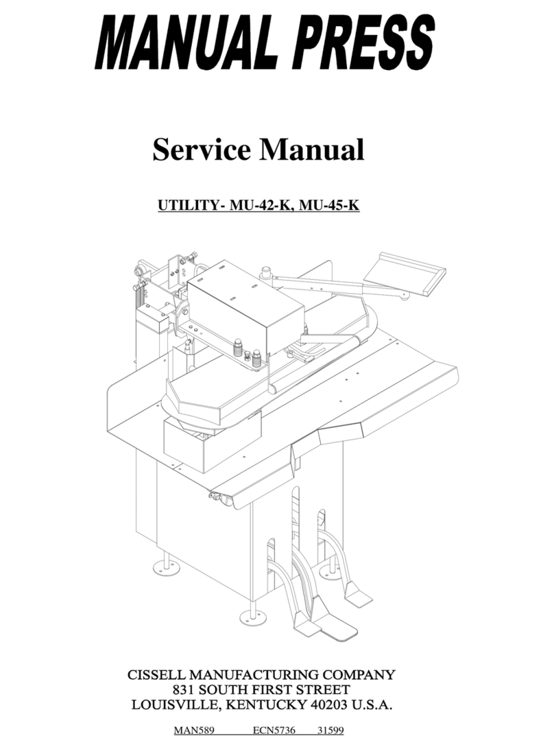
Cissell KMAN589A User manual

Cissell
Cissell KMAN589 User manual

Cissell
Cissell PANTOPAMAN39 User manual

Cissell
Cissell FMMAN58 User manual

Cissell
Cissell NEW UTILITY User manual

Cissell
Cissell MUCMAN145000 User manual