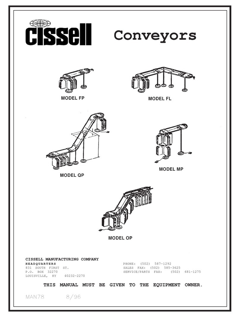
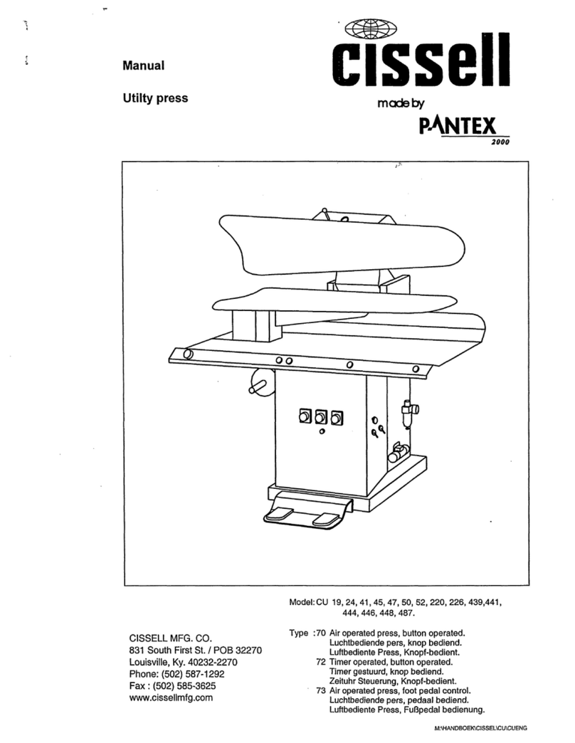
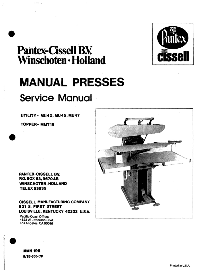
Cissell PUFFIRONDMAN343 User manual

Page 1Page 1
Page 1Page 1
Page 1
OWNER’S MANUALOWNER’S MANUAL
OWNER’S MANUAL
MAN 343 8/95MAN 343 8/95
MAN 343 8/95
Puff IronPuff Iron
Puff IronPuff Iron
Puff Iron
Model ‘D’Model ‘D’
Model ‘D’Model ‘D’
Model ‘D’
THIS MANUAL MUST BE GIVEN TO THE EQUIPMENT OWNER.THIS MANUAL MUST BE GIVEN TO THE EQUIPMENT OWNER.
THIS MANUAL MUST BE GIVEN TO THE EQUIPMENT OWNER.
CISSELL MANUFACTURING COMPANYCISSELL MANUFACTURING COMPANY
CISSELL MANUFACTURING COMPANY
HEADQUARTERSHEADQUARTERS
HEADQUARTERS PHONE:(502)587-1292
831 SOUTH FIRST ST. SALESFAX: (502)585-3625
P.O. BOX 32270 SERVICE/PARTS FAX: (502) 681-1275
LOUISVILLE,KY 40232-2270

Page 2Page 2
Page 2Page 2
Page 2
WARRANTYWARRANTY
WARRANTYWARRANTY
WARRANTY
The Cissell Manufacturing Company (Cissell) warrants all new equipment (and the original parts thereof)
to be free from defects in material or workmanship for a period of one (1) year from the date of sale thereof
toanoriginalpurchaserforuse,exceptashereinafterprovided.Withrespecttonon-durablepartsnormally
requiring replacement in less than one (1) year due to normal wear and tear, including, but not limited to,
cloth goods, valve discs, hoses, and iron cords, and with respect to all new repair or replacement parts for
Cissell equipment for which the one (1) year warranty period has expired, or for all new repair or
replacementpartsforequipmentotherthanCissellequipment,thewarrantyperiodislimitedtoninety(90)
daysfromdateofsale.ThewarrantyperiodoneachnewreplacementpartfurnishedbyCissellinfulfillment
ofthewarrantyonnewequipmentorpartsshallbefor theunexpiredportionoftheoriginalwarrantyperiod
on the part replaced.
With respect to electric motors, coin meters and other accessories furnished with the new equipment, but
not manufactured by Cissell, the warranty is limited to that provided by the respective manufacturer.
Cissell's total liability arising out of the manufacture and sale of new equipment and parts, whether under
thewarrantyorcausedbyCissell'snegligenceorotherwise,shallbelimitedtoCissellrepairingorreplacing,
atitsoption,anydefectiveequipmentorpartreturnedf.o.b.Cissell'sfactory,transportationprepaid,within
the applicable warranty period and found by Cissell to have been defective, and in no event shall Cissell be
liable for damages of any kind, whether for any injury to persons or property or for any special or
consequential damages. The liability of Cissell does not include furnishing (or paying for) any labor such
as that required to service, remove or install; to diagnose troubles; to adjust, remove or replace defective
equipment or a part; nor does it include any responsibility for transportation expense which is involved
therein.
The warranty of Cissell is contingent upon installation and use of its equipment under normal operating
conditions. The warranty is void on equipment or parts; that have been subjected to misuse, accident, or
negligent damage; operated under loads, pressures, speeds, electrical connections, plumbing, or conditions
other than those specified by Cissell; operated or repaired with other than genuine Cissell replacement
parts; damaged by fire, flood, vandalism, or such other causes beyond the control of Cissell; altered or
repaired in any way that effects the reliability or detracts from its performance, or; which have had the
identification plate, or serial number, altered, defaced, or removed.
No defective equipment or part may be returned to Cissell for repair or replacement without prior written
authorization from Cissell. Charges for unauthorized repairs will not be accepted or paid by Cissell.
CISSELL MAKES NO OTHER EXPRESS OR IMPLIED WARRANTY, STATUTORY OR OTHERWISE,
CONCERNING THE EQUIPMENT OR PARTS INCLUDING, WITHOUT LIMITATION, A WARRANTY
OF FITNESS FOR A PARTICULAR PURPOSE, OR A WARRANTY OF MERCHANTABILITY. THE
WARRANTIES GIVEN ABOVE ARE EXPRESSLY IN LIEU OF ALL OTHER WARRANTIES, EXPRESS
ORIMPLIED. CISSELLNEITHERASSUMES,NORAUTHORIZES ANY PERSONTOASSUMEFORIT,
ANY OTHER WARRANTY OR LIABILITY INCONNECTION WITHTHE MANUFACTURE, USE OR SALE
OF ITS EQUIPMENT OR PARTS.
For warranty service, contact the Distributor from whom the Cissell equipment or part was purchased. If
the Distributor cannot be reached, contact Cissell.
Page 3Page 3
Page 3Page 3
Page 3
DIMENSION DRADIMENSION DRA
DIMENSION DRAWINGSWINGS
WINGSWINGS
WINGS
All dimensions are in inches ± 1/4.

Page 4Page 4
Page 4Page 4
Page 4
INSTRUCTIONS FOR STEAM CONNECTIONS FOR PUFF IRONSINSTRUCTIONS FOR STEAM CONNECTIONS FOR PUFF IRONS
INSTRUCTIONS FOR STEAM CONNECTIONS FOR PUFF IRONS
IMPORTANT:IMPORTANT:
IMPORTANT: INSTALL STEAM PIPING IN ACCORDANCE WITHINSTALL STEAM PIPING IN ACCORDANCE WITH
INSTALL STEAM PIPING IN ACCORDANCE WITHINSTALL STEAM PIPING IN ACCORDANCE WITH
INSTALL STEAM PIPING IN ACCORDANCE WITH
ALL LOCAL REGULATIONS AND REQUIREMENTS.ALL LOCAL REGULATIONS AND REQUIREMENTS.
ALL LOCAL REGULATIONS AND REQUIREMENTS.
1. Set and anchor machine in position. Machine should be level to assure proper steam
circulation.
2. To prevent condensate draining from headers to machine, piping should have a
minimum riser 12” above each respective header as illustrated. Do not make steam
connection to header with a horizontal or downwardly facing tee or elbow.
3. Whenever possible, horizontal runs of steam must drain, by gravity, to respective
steam header. Water pocket or an improperly drained steam header will provide wet
steam cauing unecessary wetting-out of head covers.
4. In both the steam supply and steam return line, it is recommended that each have a
1/2” union and 1/2” globe valve. This will enable you to disconnect the steam
connections and block steam flow to and from machine while servicing machine.
5. Before installing trap and check valve in steam return line, open globe valve in steam
supply line to allow steam to flow through machine to flush out any dirt and scale from
machine. This will assure proper operation of trap when connected.
6. After flushing system, install bucket trap (with built-in stainer) and check valve as
illustrated. For sucessful operation of machine, install trap as close to floor and as near
to machine as possible. Inspect trap carefully for inlet and outlet marking and install
according to manufacturer instructions.
If steam is gravity-returned to boiler, omit trap but install check valve in return line
near machine.
7. Install union and globe valve to return line and make final pipe connection to return
header.
CAUTION:CAUTION:
CAUTION:CAUTION:
CAUTION: Before operating Puff Iron, open globe valves in steam lines
and allow Puff Iron to warm up. Under no circumstances
should machine be operated until hot.
RECOMMENDATIONSRECOMMENDATIONS
RECOMMENDATIONS
1. Use a separate trap for each unit. Always keep the trap clean and in good working
condition.
2. When machine is on the end of a line of equipment, extend headers at least 4 ft. beyond
machine. Install globe valve, union, check valve trap and optional by-pass at the end of
a line. If gravity return to boiler, omit trap.
3. Insulate steam supply and return line for safety of operator and safety while servicing
machine.
4. Keep machine in good working condition. Repair or replace any worn or defective parts.

Page 5Page 5
Page 5Page 5
Page 5
STEAM PIPINGSTEAM PIPING
STEAM PIPING
For wet line conditions, trap w/strainer and
check valve should be installed (dotted lines).
12” Minimum Risers
RETURN
SUPPLY
All piping parts beyond connection
points to be furnished by customer.
CENTRAL AIR VACUUM
1-1/4” Vacuum
Connection
3/4” Return
Connection
3/4” Elbow
12” Drop
3/4” x 1/2”
Elbow
1/2” Pipes
Globe
Valves
1/2”
Supply
Connection
SUPPLY
RETURN
Check Valve
Bucket Trap w/Strainer
(Thermodynamic Trap and
Y-Strainer may be substituted)

Page 6Page 6
Page 6Page 6
Page 6
PUFF IRONPUFF IRON
PUFF IRONPUFF IRON
PUFF IRON TT
TT
TABLEABLE
ABLEABLE
ABLE ARRANGEMENTSARRANGEMENTS
ARRANGEMENTSARRANGEMENTS
ARRANGEMENTS
Note head centers on tables shown. Angular Corner and Back
used for angle arrangement. Square Extension with bracket
used with No. 4X, 4C or 4 Sleever for extra working space.
Drawings show in-line or angle arrangement of one
Double Table and one Single Table. Note use of
Angular Corner and Square Extension.
SINGLE TABLESINGLE TABLE
SINGLE TABLE
One 15-1/2” SINGLE TABLE.One 15-1/2” SINGLE TABLE.
One 15-1/2” SINGLE TABLE.
Unit includes No. 1M Men’s
Shoulder.
SINGLE TABLESINGLE TABLE
SINGLE TABLE
One 15-1/2” SINGLE TABLE.One 15-1/2” SINGLE TABLE.
One 15-1/2” SINGLE TABLE.
Unit includes No. 4C Sleever
with 12” extension.
Drawing shows suggested
heads on 38” Triple Table.
PUFF IRON SPECIFICAPUFF IRON SPECIFICA
PUFF IRON SPECIFICATIONSTIONS
TIONSTIONS
TIONS
Steam Pressure ......................................................................................... 60-100 P.S.I.G.
(4.14 - 6.9 Bars)
Steam Supply................................................................................... 1/2” Pipe Connection
Steam Return................................................................................... 3/4” Pipe Connection
Vacuum Connection.............................................................................. 1-1/4” Connection
Vacuum Requirement.........................................................................1/4” Press Capacity
Boiler Horsepower
Single Puff Iron Table .......................................................................... 1/8 H.P.
Double Puff Iron Table......................................................................... 1/4 H.P.
Triple Puff Iron Table........................................................................... 3/8 H.P.
APPROXIMAAPPROXIMA
APPROXIMAAPPROXIMA
APPROXIMATE SHIPPINGTE SHIPPING
TE SHIPPINGTE SHIPPING
TE SHIPPING WEIGHTSWEIGHTS
WEIGHTSWEIGHTS
WEIGHTS
UNITUNIT
UNITUNIT
UNIT
(with fabric pressing heads)(with fabric pressing heads)
(with fabric pressing heads)
33” Double Table with 2 and
4-C with extension and bracket.
33” Double Table with 1-L, 2;
15-1/2” Single Table with 4-C
with extension and bracket.
15-1/2” Single Table with 1-M
Shoulder
(without fabric pressing heads)(without fabric pressing heads)
(without fabric pressing heads)
33” Double Table with 2 and
4-C with extension and bracket.
38” Triple Table with 1-L, 2
4-C with extension and bracket.
15-1/2” Single Table with 1-M
Shoulder
DOMESTICDOMESTIC
DOMESTICDOMESTIC
DOMESTIC
215 lbs. (97.5 kg.)
175 lbs. (79.4 kg.)
62 lbs. (28.1 kg)
195 lbs. (88.5 kg.)
125 lbs. (56.7 kg.)
57 lbs. (25.9 kg.)
EXPORTEXPORT
EXPORTEXPORT
EXPORT
465lbs.(210.9 kg.)
415lbs.(188.2 kg.)
105 lbs. (47.6 kg)
445lbs.(201.9 kg.)
275lbs.(124.7 kg.)
100 lbs. (45.7 kg.)
EXPORT SHIPPINGEXPORT SHIPPING
EXPORT SHIPPING
DIMENSIONSDIMENSIONS
DIMENSIONS
74” x 23” x 53” (188 cm x 58 cm x
135 cm) 52.2 cu. ft. (1.48 m³)
66” x 23” x 51” (168 cm x 58 cm x
130 cm) 44.8 cu. ft. (1.27 m³)
18” x 15” x 53” (46 cm x 38 x
135 cm) 8.3 cu. ft. (0.24 m³)
74” x 18” x 50” (188 cm x 46 cm x
127 cm) 38.5 cu. ft. (1.09 m³)
41” x 29” x 47” (104 cm x 74 cm x
119 cm) 32.2 cu. ft. (0.91 m³)
20” x 15” x 50” (51 cm x 38 cm x
127 cm) 8.7 cu. ft. (0.25 m³)

Page 7Page 7
Page 7Page 7
Page 7
Support Bars
See Separate Page
PUFF IRONPUFF IRON
PUFF IRONPUFF IRON
PUFF IRON “D”“D”
“D”“D”
“D” MODELMODEL
MODELMODEL
MODEL TT
TT
TABLE PABLE P
ABLE PABLE P
ABLE PARTSARTS
ARTSARTS
ARTS
Ref. No.Ref. No.
Ref. No.Ref. No.
Ref. No. Part No.Part No.
Part No.Part No.
Part No. DescriptionDescription
DescriptionDescription
Description
1 TU7733 #8 x 1/2” Self Drill Screw
(Pkg. of 6)
2 F225 Spacer Ring (Return)
3 P454 Right Table Leg
4 P219 Truss Hd. Bolt, 1/4 -
20 x 1/2”
5 P165 Triple Top - 38”
6 P153 Double Top - 33”
7 P154 Single Top - 15-1/2”
8 TU2847 Cut Washer, 1/4”
Ref. No.Ref. No.
Ref. No.Ref. No.
Ref. No. Part No.Part No.
Part No.Part No.
Part No. DescriptionDescription
DescriptionDescription
Description
9 TU2846 Lockwasher, 1/4”
10 TU4934 Hex Nut, 1/4” - 20
11 P509 Phillips Screw, 1/4” -
20 x 5/8”
12 P455 Left Table Leg
13 P513 Triple Front Panel Asm.*
14 P512 Double Front Panel Asm.*
15 P511 Single Front Panel Asm.*
16 P528 Spacer Ring (Supply)
* Consists of Front Panel, Cissell Namplate, screws and washers.
NOTE: For service, new design allows easy access from front of machine
by removing front panel screws and washers. Nuts are welded to
table legs.

Page 8Page 8
Page 8Page 8
Page 8
TT
TT
TABLE BACKSABLE BACKS
ABLE BACKSABLE BACKS
ABLE BACKS,,
,,
,CORNER,CORNER,
CORNER,CORNER,
CORNER, EXTENSION & BRACESEXTENSION & BRACES
EXTENSION & BRACESEXTENSION & BRACES
EXTENSION & BRACES
Ref. No.Ref. No.
Ref. No.Ref. No.
Ref. No. Part No.Part No.
Part No.Part No.
Part No. DescriptionDescription
DescriptionDescription
Description
1 P155 Back, Single Table
2 P158 Back, Single w/Extension
3 P159 Back, Double Table
4 P167 Back, Triple Table
5 P161 Back, Double w/Extension
6 P166 Back, Triple w/Extension
7 P219 Tr. Hd. Scw. 1/4”-20 x 1/2”
8 TU2846 Lockwasher, 1/4”
9 TU4934 Hex Nut, 1/4-20
10 P189 17” Corner and Back
Ref. No.Ref. No.
Ref. No.Ref. No.
Ref. No. Part No.Part No.
Part No.Part No.
Part No. DescriptionDescription
DescriptionDescription
Description
11 P156 12” x 12” Extension
P505 Extension w/Brace &
Hardware for Single
or Triple
P507 Extension w/Brace &
Hardware for Double
13 P483 Extension Brace for Single
& Triple
14 P484 Extension Brace for
Double Table

Page 9Page 9
Page 9Page 9
Page 9
VV
VV
VACUUM MANIFOLD PACUUM MANIFOLD P
ACUUM MANIFOLD PACUUM MANIFOLD P
ACUUM MANIFOLD PARTSARTS
ARTSARTS
ARTS
Ref. No.Ref. No.
Ref. No.Ref. No.
Ref. No. Part No.Part No.
Part No.Part No.
Part No. DescriptionDescription
DescriptionDescription
Description
1 P252 Hose Adapter
2 P523 Vacuum Manifold, Triple Table*
3 P257 Vacuum Manifold, Double Table*
4 P284 Vacuum Manifold, Single Table*
5 P253 Manifold Cap, 1-1/2”
6 P271 Adapter Cap, 3/4”
7 M263 #8 - 3/8” S.M.S.
8 P256 Pipe Clamp
9 P276 “O” Ring
10 P277 Union w/“O” Ring
* Includes Hose Adapter(s)

Page 10Page 10
Page 10Page 10
Page 10
For Egg Heads Only,
Use P527 Flow Control Valve

Page 11Page 11
Page 11Page 11
Page 11
SINGLESINGLE
SINGLESINGLE
SINGLE TT
TT
TABLE -ABLE -
ABLE -ABLE -
ABLE - VV
VV
VALAL
ALAL
ALVESVES
VESVES
VES AND RELAAND RELA
AND RELAAND RELA
AND RELATED PTED P
TED PTED P
TED PARTSARTS
ARTSARTS
ARTS
Puff Iron “D” Models without VacuumPuff Iron “D” Models without Vacuum
Puff Iron “D” Models without Vacuum
Ref. No.Ref. No.
Ref. No.Ref. No.
Ref. No. Part No.Part No.
Part No.Part No.
Part No. DescriptionDescription
DescriptionDescription
Description
1 TU4599 Steam Pipe, 3/4” x 18”
2 P262 Jacket
3 P266 Flange
4 P466 90° Fitting, 3/8”P x 1/4”T
5 P470 Disc Valve Assembly
P504 Renewable Disc
P506 Packing
6 390401246 Nipple, 3/8” x 3-1/2”
7 TU4607 Nipple, 3/4” x 2-1/2”
8 P273 Carriage Bolt, 5/16” - 18 x 3/4”
9 M280 Carriage Bolt, 1/4” - 20 x 1”
10 390401013 Nipple, 1/2” x 7”
11 OP267 Bushing, 3/4” x 1/2”
12 P459 Cross, 3/4”
13 P460 Bushing, 3/4” x 1/4”
14 P461 Fitting, St. 1/4”P x 1/4”T
15 P519 Straight Upsteam Tube Assembly
16 390401031 Nipple, 3/4” x Close
17 OP267 Bushing, 3/4” x 1/2”
18 P115 Tee, 3/4” x 3/4” x 3/8”
19 TU4598 Nipple, 3/4” x 6”
20 P465 Valve Rod
21 TU2814 Lockwasher, 5/16”
22 C249 Hex Nut, 5/16 - 18
23 TU4934 Hex Nut, 1/4 - 20
24 TU2846 Lockwasher, 1/4”
25 SF49 Yoke Assembly
26 P228 Foot Pedal
27 P132 Support Bar
28 P98 Collar
29 P126 Set Screw, 1/4” - 20
30 P36 Pedal Wrench
31 TU4600 Union, 3/4”
32 P525 “L” Shaped Tube
33 OP297 Straight Connector, 1/8”P x 1/4”T
34 OP268 Reducing El, 1/4”P x 1/8”P
35 P524 90° Connector, 1/4”P x 1/4”T
36 P526 Insulation
37 P529 Insulation

Page 12Page 12
Page 12Page 12
Page 12
For Egg Heads Only,
Use P527 Flow Control Valve

Page 13Page 13
Page 13Page 13
Page 13
DOUBLEDOUBLE
DOUBLEDOUBLE
DOUBLE TT
TT
TABLE -ABLE -
ABLE -ABLE -
ABLE - VV
VV
VALAL
ALAL
ALVESVES
VESVES
VES AND RELAAND RELA
AND RELAAND RELA
AND RELATED PTED P
TED PTED P
TED PARTSARTS
ARTSARTS
ARTS
Puff Iron “D” Models without Vacuum
Ref. No.Ref. No.
Ref. No.Ref. No.
Ref. No. Part No.Part No.
Part No.Part No.
Part No. DescriptionDescription
DescriptionDescription
Description
1 P266 Flange
2 OP296 Nipple, 1/2” x 5”
3 TU4599 Steam Pipe, 3/4” x 18”
4 P262 Jacket
5 P466 90° Fitting, 3/8”P x 1/4”T
6 P470 Disc Valve Assembly
P504 Renewable Disc
P506 Packing
7 390401246 Nipple, 3/8” x 3-1/2”
8 TU4607 Nipple, 3/4” x 2-1/2”
9 OP267 Bushing, 3/4” x 1/2”
10 P459 Cross, 3/4”
11 P460 Bushing, 3/4” x 1/4”
12 P461 Fitting, 1/4”P x 1/4”T
13 390401031 Nipple, 3/4” x Close
14 P115 Tee, 3/4” x 3/4” x 3/8”
15 TU4610 Nipple, 3/4” x 5”
16 TU4600 Union, 3/4”
17 P273 Carriage Bolt, 5/16” - 18 x 3/4”
18 M280 Carriage Bolt, 1/4” - 20 x 1”
19 P266 Flange
20 TU2846 Lockwasher, 1/4”
21 TU4934 Hex Nut, 1/4” - 20
22 TU2814 Lockwasher, 5/16”
23 C249 Hex Nut, 1/4” - 20
24 P519 Straight Upsteam Tube Assembly
25 P465 Valve Rod
26 SF49 Yoke Assembly
27 P228 Foot Pedal
28 P177 Support Bar
29 P98 Collar
30 P126 Set Screw, 1/4” - 20
31 P36 Pedal Wrench
32 P525 “L” Shaped Tube
33 OP297 Straight Connector, 1/8”P x 1/4”T
34 OP268 Reducing El, 1/4”P x 1/8”P
35 P524 90° Connector, 1/4”P x 1/4”T
36 P526 Insulation
37 P529 Insulation
38 TU4598 Nipple, 3/4” x 6”
39 P532 Steam Valve Rod - Used on Vacuum Models Only
for Right Side Head

Page 14Page 14
Page 14Page 14
Page 14
For Egg Heads Only,
Use P527 Flow Control Valve

Page 15Page 15
Page 15Page 15
Page 15
TRIPLETRIPLE
TRIPLETRIPLE
TRIPLE TT
TT
TABLE -ABLE -
ABLE -ABLE -
ABLE - VV
VV
VALAL
ALAL
ALVESVES
VESVES
VES AND RELAAND RELA
AND RELAAND RELA
AND RELATED PTED P
TED PTED P
TED PARTSARTS
ARTSARTS
ARTS
Puff Iron “D” Models without Vacuum
Ref. No.Ref. No.
Ref. No.Ref. No.
Ref. No. Part No.Part No.
Part No.Part No.
Part No. DescriptionDescription
DescriptionDescription
Description
1 TU4599 Steam Pipe, 3/4” x 18”
2 P262 Jacket
3 P266 Flange
4 P466 90° Fitting, 3/8”P x 1/4”T
5 P470 Disc Valve Assembly
P506 Packing
P504 Renewable Disc
6 390401246 Nipple, 3/8” x 3-1/2”
7 TU2862 Nipple, 3/4” x 6-1/2”
8 TU4651 Nipple, 1/2” x 6”
9 OP267 Bushing, 3/4” x 1/2”
10 P459 Cross, 3/4”
11 P460 Bushing, 3/4” x 1/4”
12 P461 Fitting, 1/4”P x 1/4”T
13 P519 Straight Upsteam Tube Assembly
14 390401031 Nipple, 3/4” x Close
15 P115 Tee, 3/4” x 3/4” x 3/8”
16 TU4607 Nipple, 3/4” x 2-1/2”
17 TU4600 Union, 3/4”
18 TU4608 Nipple, 3/4” x 2”
19 P465 Valve Rod
20 SF49 Yoke Assembly
21 P228 Foot Pedal
22 M280 Carriage Bolt, 1/4” - 20 x 1”
23 P273 Carriage Bolt, 5/16” - 18 x 3/4”
24 TU2846 Lockwasher, 5/16”
25 TU4934 Hex Nut, 1/4” - 20
26 TU2814 Lockwasher, 5/16”
27 C249 Hex Nut, 5/16” - 18
28 P98 Collar
29 P126 Set Screw, 1/4” - 20
30 P36 Pedal Wrench
31 P133 Support Bar
32 P525 “L” Shaped Tube
33 OP297 Straight Connector, 1/8”P x 1/4”T
34 OP268 Reducing El, 1/4”P x 1/8”P
35 P524 90° Connector, 1/4”P x 1/4”T
36 P526 Insulation
37 P529 Insulation
38 TU4598 Nipple, 3/4” x 6”
39 P532 Steam Valve Rod - Used on Vacuum Models Only
for Right Side Head

Page 16Page 16
Page 16Page 16
Page 16
CENTRALCENTRAL
CENTRALCENTRAL
CENTRAL AIRAIR
AIRAIR
AIR VV
VV
VACUUM PACUUM P
ACUUM PACUUM P
ACUUM PARTSARTS
ARTSARTS
ARTS
P503 - Vacuum Valve Assembly consists of
parts 6 - 16
Ref.Ref.
Ref.Ref.
Ref. PartPart
PartPart
Part
No.No.
No.No.
No. No.No.
No.No.
No. DescriptionDescription
DescriptionDescription
Description
1 TU4599 Steam Pipe
2 P260 Vacuum Pipe 3/8” x 7-1/2”
3 P298 Jacket
4 P299 Flange Adapter
5 P267 Flange
6 P301 Vacuum Tube w/Spring
7 P226 Valve Seat
8 P246 Valve Seal w/Stem
9 P244 Spring
10 P223 Valve Body
11 P252 Hose Adapter
12 P502 Rubber Tube - 7-7/8”
13 P501 Valve Bracket
14 OP547 Lock Nut, 3/4” - 16
15 P237 Pivot
16 V15 Small Lock Nut
17 FB298 Vacuum Pedal Rod
18 SF49 Yoke Assembly
19 P98 Collar
20 P228 Foot Pedal
21 P531 Vacuum Rod - Used for
Right Side Head Only

Page 17Page 17
Page 17Page 17
Page 17
HEADHEAD
HEADHEAD
HEAD ASSEMBLIESASSEMBLIES
ASSEMBLIESASSEMBLIES
ASSEMBLIES
Consists of Head, Steam Spreader and Gasket
Ref. No. Part No. Description
Regular Vacuum Nylon Cover
& Flannel Pad
1 P477 PV477 P146 No. 4C (22”) Sleever Head
2 P476 PV476 P78 No. 4X (22”) Sleever Head
3 P475 PV475 P77 No. 4 (14”) Sleever Head
4 P471 PV471 P74 No. 1L Ladies Shoulder Head
5 P474 PV474 P75 No. 2 Mushroom Head
6 P472 PV472 P112 No. 1E Men’s Shoulder Head
7 P473 PV473 P83 No. 1M Men’s Shoulder Head
8 P479 P76 No. 3 Egg Head
9 P457 Steam Spreader (all except Egg)
P458 Steam Spreader (Egg only)
10 P44 Copper Gasket
P210 4-Way Set of Puff Iron Nylon
Covers and Flannel Pads for 3, 1L,
2 amd 4C Cissell Puff Iron Heads
(Not Illustrated)
P211 3-Way Set of Puff Iron Nylon
Covers and Flannel Pads for 1L,
2 amd 4C Cissell Puff Iron Heads
(Not Illustrated)
11 P145 8-Inch Nylon Hand Pad (Optional)
12 P37 Head Seat Wrench, 5/16”

Page 18Page 18
Page 18Page 18
Page 18
FABRIC PRESSING HEAD PFABRIC PRESSING HEAD P
FABRIC PRESSING HEAD PARTSARTS
ARTSARTS
ARTS
Ref. No.Ref. No.
Ref. No.Ref. No.
Ref. No. Part No.Part No.
Part No.Part No.
Part No. DescriptionDescription
DescriptionDescription
Description
1 PIF163 Swinging Arm
2 PIF162 Support Upright
3 PIF161 Support Base
4 X54 Handle End
5 X56 Cork Handle
6 S9 Handle Belt
7 PIF169 Support Holder
8 PIF204 Stop
9 PIF172 Delrin Bushing
10 PIF164 Spacer
11 PIF167 Pivot Stud
12 V12 Gland
13 V345 Spring
14 PIF202 Latch
15 PIF154 Extension Spring
Ref. No.Ref. No.
Ref. No.Ref. No.
Ref. No. Part No.Part No.
Part No.Part No.
Part No. DescriptionDescription
DescriptionDescription
Description
16 C396 Crown Nut, 1/4 - 20
17 TU2846 Lockwasher, 1/4”
18 P219 Tr. Hd. Scw., 1/4” - 20 x 1/2”
19 S20 #8 - 32 Crown Nut
20 AT368 Lockwasher, #8
21 TU4820 Cut Washer, #10
22 RC355 Hex Cap Scw., 1/4” - 28 x 1 - 1/2”
23 IB143 Hex Nut, 1/4” - 28
24 TU2847 Cut Washer, 1/4”
25 P302 Tr. Hd. Scw. 1/4” - 20 x 1”
26 J10 Eye Bolt
27 VSB154 Wing Nut, #10 - 24
28 P163 Large Adapter, 4C or 4X
29 P164 Small Adapter, 4 Sleever
30 TU4934 Hex Nut, 1/4” - 20

Page 19Page 19
Page 19Page 19
Page 19
Ref. No.Ref. No.
Ref. No.Ref. No.
Ref. No. Part No.Part No.
Part No.Part No.
Part No. DescriptionDescription
DescriptionDescription
Description
1 PIF155 Fabric Head Support Arm
2 PIF148 Fabric Head Ring w/Screen
and Cloth (For No. 1E Men’s
or No. 1 L Ladies Shoulder)
3 PIF157 Fabric Head Support Arm
4 PIF152 Fabric Head Ring w/Screen
and Cloth (For No. 1M Men’s
Shoulder)
5 PIF156 Fabric Head Support Arm
6 PIF149 Fabric Head Ring w/Screen
and Cloth (For No. 2
Mushroom)
7 PIF158 Fabric Head Support Arm
8 PIF150 Fabric Head Ring w/Screen
and Cloth (For #4 (14”)
Sleever)
Ref. No.Ref. No.
Ref. No.Ref. No.
Ref. No. Part No.Part No.
Part No.Part No.
Part No. DescriptionDescription
DescriptionDescription
Description
9 PIF160 Fabric Head Support Arm
10 PIF153 Fabric Head Ring w/Screen
and Cloth (For No. 4C (22”)
Sleever)
11 PIF159 Fabric Head Support Arm
12 PIF151 Fabric Head Ring w/Screen
and Cloth (For No. 4X (22”)
Sleever)
13 IB143 1/4” - 28 Hex. Hd. Nut
14 TU2846 1/4” Lockwasher
15 FB190 1/4” - 28 x 2” Hex Head Scw.
16 P302 1/4” - 20 x 1” Truss Hd.
Mach. Screw
17 TU4934 1/4” - 20 Hex Nut

Page 20Page 20
Page 20Page 20
Page 20
WW
WW
WAA
AA
ATER SPRATER SPRA
TER SPRATER SPRA
TER SPRAY GUNY GUN
Y GUNY GUN
Y GUN ANDAND
ANDAND
AND
CONDENSERCONDENSER
CONDENSERCONDENSER
CONDENSERASSEMBLASSEMBL
ASSEMBLASSEMBL
ASSEMBLYY
YY
Y
P391
Ref.Ref.
Ref.Ref.
Ref. PartPart
PartPart
Part
No.No.
No.No.
No. No.No.
No.No.
No. DescriptionDescription
DescriptionDescription
Description
1 SG89 1/4” L Shaped Pipe
2 OP329 Large Hose Clamp
3 J17 “S” Hook
4 SG38 Suspension Spring
5 GSB145 Small Hose Clamp
6 OP268 90° Reducing Pipe EL 1/4” x 1/8”
(2 Req’d)
7 SGV35 Brass Adapter
8 SG25 Hose Gasket
9 SG37 5 Ft. Water Hose Assembly
10 SGO43 Overhead Water Spray Gun
(See Separate Part Sheet)
11 SG49 Bracket for Water Spray Gun
12 SG50 “J” Bolt
13 SG90 1/4” Tubing 31” Long
14 SGV1 Valve (See Separate Part Sheet)
15 SGC2 Condenser (See Separate Part
Sheet)
16 TU4604 3/4” x 9-3/4” Black Pipe
17 TU4595 3/4” x 1/2” x 3/4” Pipe Tee
18 TU2714 1/2” Close Nipple
19 J21 1/4” - 20 x 3/4” Sq. Hd. Set
Screw
20 V56 5/16” - 20 Hex Nut
21 OP297 1/4” Tube x 1/8” Pipe Straight
Connection w/Nut & Bead
22 PU8 1/4” Bead
23 SU65 1/4” Nut
This manual suits for next models
1
Table of contents
Other Cissell Sander manuals

Cissell
Cissell PANTOP24VMAN594 User manual

Cissell
Cissell FMMAN58 User manual

Cissell
Cissell PANTOPAMAN39 User manual

Cissell
Cissell PANTOPBMAN309 User manual

Cissell
Cissell KMAN589 User manual

Cissell
Cissell MAN78 User manual

Cissell
Cissell PANTOPBEXCMAN309X User manual

Cissell
Cissell GENIEMAN59 User manual

Cissell
Cissell NEW UTILITY User manual

Cissell
Cissell CF 487 User manual