WhisperPower M-SQ7 User manual

INSTALLATION MANUAL U.S.A EDITION
M-SQ7
- 1800 RPM -
Marine diesel generating set 120/240V / 60Hz
Digital Diesel Control
V1 October 2010
Art.nr. 40200464
WHISPER POWER BV
Kelvinlaan 82
9207 JB Drachten
Netherlands
Tel.: +31-512-571550
Fax.: +31-512-571599
www.whisperpower.eu

TABLE OF CONTENTS
2October 2010 / M-SQ7 / US
TABLE OF CONTENTS:
1INSTALLATION............................................................................................................................................................... 3
1.1 General ..............................................................................................................................................................3
1.2 Location..............................................................................................................................................................3
1.3 Instructions for optimal sound and vibration insulation.......................................................................................3
1.4 Ventilation...........................................................................................................................................................4
1.5 Connections .......................................................................................................................................................4
1.5.1 Fuel supply........................................................................................................................................6
1.5.2 Cooling..............................................................................................................................................7
1.5.3 Exhaust system...............................................................................................................................11
1.5.4 Digital Diesel Control system (12 Volt)............................................................................................14
1.5.5 AC power system (120 - 240 Volt)...................................................................................................16
2INSTALLATION SPECIFICATIONS.............................................................................................................................. 18
2.1 General ............................................................................................................................................................18
2.2 Commission table.............................................................................................................................................18
2.3 Installation specifications..................................................................................................................................19
2.4 Specification of the accessories.......................................................................................................................19
2.5 Installation materials.........................................................................................................................................20
3DIAGRAMS & DRAWINGS ........................................................................................................................................... 26
3.1 DC wiring M-SQ7 .............................................................................................................................................26
3.2 Diagram electronic governor ............................................................................................................................28
3.3 AC wiring diagram 120 - 240V / 60Hz .............................................................................................................. 29
3.4 Remote control panel drawings........................................................................................................................30
3.5 Dimensions M-SQ7..........................................................................................................................................31

INSTALLATION
US / M-SQ7 / October 2010 3
1 INSTALLATION
1.1 GENERAL
This installation manual is valid for the following models:
Part
number Description
41105055 M-SQ7 120/240V 1800RPM
41105056 M-SQ7 120/240V 1800RPM -ungrounded
For other models see our website: www.whisperpower.eu.
To ensure reliability and durability of the equipment, it is
very important that the installation is carried out with the
utmost care and attention. To avoid problems, such as
temperature problems, noise levels, vibration, etc. the
instructions set out in this manual must be followed and all
installation work must be carried out professionally.
1.2 LOCATION
Since WhisperPower generating sets have extremely
compact dimensions, they can be installed in tight
locations. Please consider that even almost maintenance-
free machinery must still remain accessible.
When selecting the location area in which to mount the
generating set, make sure there is sufficient room to carry
out any maintenance work. The unit must be easily
accessible on the service side and on the distribution side
to have access to the V-belt
Please also note that in spite of the automatic oil pressure
sensor it is still essential that the oil level is checked
regularly.
1.3 INSTRUCTIONS FOR OPTIMAL SOUND
AND VIBRATION INSULATION
Position the generating set as low as possible in the
vessel. As the generating set is already secured to the
base frame by means of flexible engine mountings, the
frame must be mounted directly, without additional
vibration dampers, to the vessel’s main structure.
WhisperPower generating sets are standard equipped with
a sound cover. The canopy has been designed to give
effective sound insulation. For optimum sound and
vibration dampening, the following factors should be
considered.
1 Most important is the structure on which the generator
is places to be stiff. Directly below the rubber
mountings the structure should be supported vertically
to the superstructure of the ship.
2 Avoid mounting the generating set in close proximity
to thin walls or floors that may cause resonance.
3 Sound dampening is extremely poor if the generating
set is mounted on a light weight flimsy surface such
as plywood which will only amplify vibrations. If
mounting on a thinner surface cannot be avoided, this
should be at least be reinforced with stiffening struts
or ribbing. If possible, holes should be drilled or cut
through the surface to help reduce the resonance.
Covering the surrounding walls and floors with a
heavy coating plus foam will certainly improve the
situation.
4 Never connect the base of the generating set directly
to bulkheads or tanks.
Figure 1: Mounting of the Whisper generating set. X = wrong, V = OK

INSTALLATION
4October 2010 / M-SQ7 / US
1.4 VENTILATION
The generating set normally draws air from the engine
room. Engine rooms with natural ventilation must have
vent openings of adequate size and location to enable the
generating set to operate without overheating. To allow an
ample supply of air within the temperature limits of the
generating set an opening of at least 16 sq inch (100 cm2)
is required.
A "sealed" engine compartment must have a good
extraction ventilator to maintain reasonable engine room
temperatures. High temperature of intake air reduces
engine performance and increases engine coolant
temperatures. Air temperatures above 104°F (40°C)
reduce the engine power by 1% for each 5°F of rise. To
minimise these effects the engine room temperature must
not be more than 27ºF (15 ºC) above the outside ambient
air temperature.
Apply a combination of ventilators, blowers and air intake
ducting to meet the temperature limit. The air inlet ducts
should run to the bottom of the engine room to clear fumes
from the bilge and to circulate fresh air. Air outlets should
be at the top of the engine room to remove the hottest air.
An engine room blower should be used as an extraction
ventilator to remove air from the engine room.
In cases where it is impossible to meet the above
mentioned temperature limit by using machine room
ventilation, connections are to be made for an air inlet
directly to the enclosure. With these connections the
generating set can be directly connected to an air duct.
Air inlets should be louvered, where appropriate, to protect
the engine room and to protect the generating set from
water spray. As an extra precaution, the fitting of a cowl
ventilator with a cover box located as high as possible, is
recommended.
1.5 CONNECTIONS
The generating set comes supplied with all supply lines
and output cable (i.e. electric cables, cooling water
connections, exhaust, fuel lines etc.) already connected to
the engine and generator. The supply lines are fed through
the capsule’s front base. The connections are marked as
shown in figure 2
All electrical connections, cable types and sizes must
comply with the appropriate national regulations. Supplied
cables are rated for ambient temperatures up to 158ºF
(70°C). If the cables are required to meet higher
temperature requirements, they must be run through
conduits.
ATTENTION!
Before working (installation) on the system
read the section safety instructions.

INSTALLATION
US / M-SQ7 / October 2010 5
Fig. 2 Connections M-SQ7
01 Raw water inlet Ø 3/4"
(Ø19mm)
02 Fuel out Ø5/16” (8
mm)
03 Battery + AWG 3
(25mm2)
04 Battery – AWG 3
(25mm2)
05 Fuel in Ø5/16” (8 mm)
06 Expansion tank
Ø5/16” (8 mm)
07 Bypass cooling water
out Ø3/4" (Ø19mm)
08 Bypass cooling water
in Ø3/4" (Ø19mm)
09 Exhaust hose Ø 1 5/8’
(40mm)
10 AC power output
11 Remote control
12 Engine air intake

INSTALLATION
6October 2010 / M-SQ7 / US
1.5.1 Fuel supply
1 FUEL TANK
Fuel tanks should be made of appropriate material such as
(stainless) steel or plastic. Steel tanks should not be
galvanised or painted inside. Condensation can occur in
metal tanks when temperature changes. Therefore, water
accumulates at the bottom of the tank and provisions
should be made for the drainage of this water.
The tank will need a filling connection, a return connection
and an air ventilation connection which will require
protection against water entry.
Some official regulations do not allow connection points at
the base of the fuel tank; in this instance connections are
to be made at the top of the tank with internal tubing down
to a few cm above the bottom of the tank.
Fig. 3 Fuel supply (fuel tank is above the generating set)
1 Fuel return
2 Fuel supply 3 Prefilter / Water separator (optional)
5 Fuel Tank
A
1
3
2
5
4
Fig. 4 Fuel supply (fuel tank is below the generating set)
1 Fuel return
2 Fuel supply
3 Prefilter / Water separator (optional)
4 Extra fuel lift pump (optional)
5 Fuel tank

INSTALLATION
US / M-SQ7 / October 2010 7
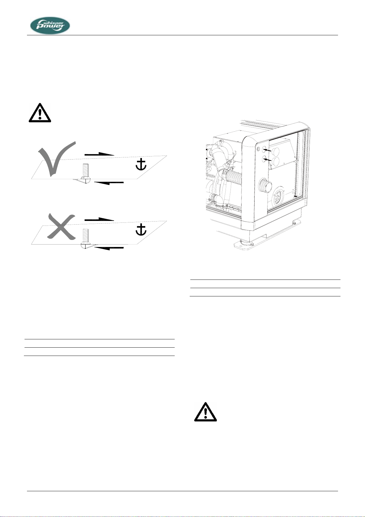
2 FUEL LIFT PUMP
The generating set itself is equipped with a fuel lift pump;
therefore the tank can be installed at a lower level than the
generating set. The maximum suction height is 1 m.
If the pump has to lift the fuel higher than one meter an
external fuel lift pump must be installed. The control board
is already prepared to connect an extra fuel pump.
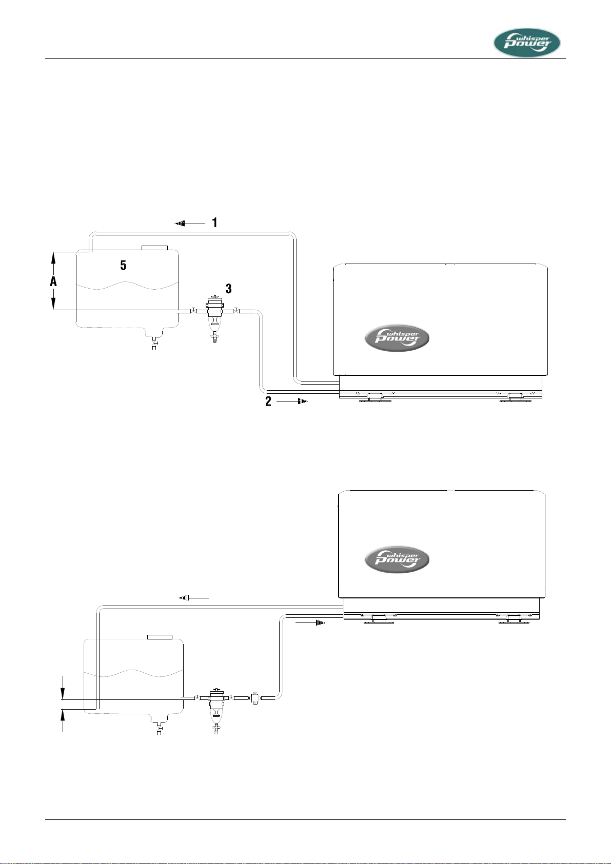
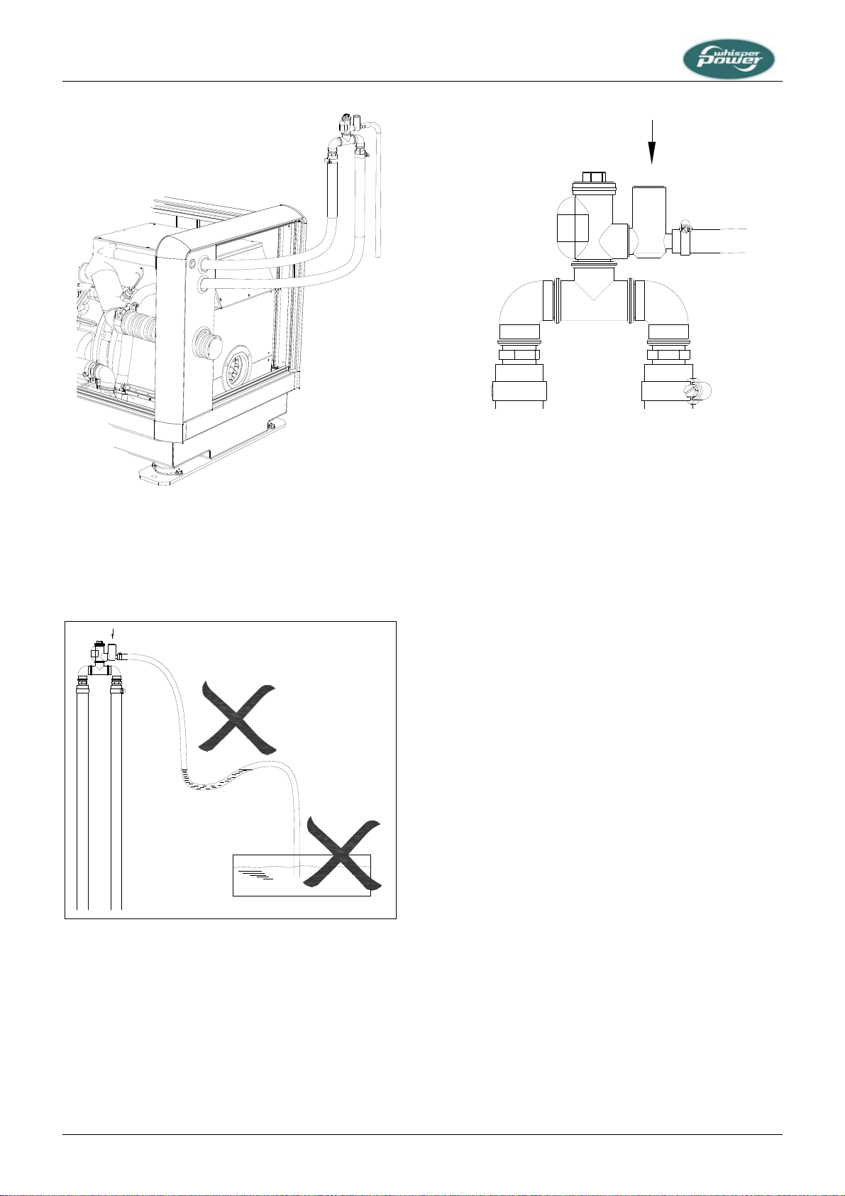
3 FUEL PIPES
When the tank is above the generating set we recommend
ending the return line on the top of the tank.
When the return is on the top - in case of a leakage the
return line cannot overflow because of siphoning. One will
only need a fuel cock in the fuel supply line. When the tank
is below the generating set we recommend ending the
return line on the bottom of the tank (A) below the inlet of
the supply line.
Both supply and return fuel pipe lines should be
appropriate material and 5/16” (8 mm) outer diameter
tubing. The quality of the tubing of fuel pipes could be
submitted to local regulations depending on the application
of the vessel.
The fuel pipes can be plumbed to the flexible hoses which
are on the generating set and have a connection to fit to
5/16” (8 mm) pipe. This fuel lines fulfils CE standards and
are according to ISO 7840 A2.
It is important to avoid bends in the pipes, as they could
trap air bubbles. The return pipe should never be
connected to the suction pipe. Other consumers of diesel
fuel, such as the propulsion engine and heaters, have to
be connected to separate suction and return pipes
4 FUEL FILTERS
A fine fuel filter is installed which requires maintenance.
WhisperPower advises to install an extra fuel filter/ water
fuel separator near the fuel tank.
Before starting your generating set for the first time follow
the fuel system bleeding procedure in the users manual.
1.5.2 Cooling
Intercooling is based on a raw water pump, heat
exchanger and water-injected exhaust. Cooling liquid in
the internal cooling system is cooled in a heatexchanger
by outboard water (raw water or seawater). After the raw
water is warmed up in the heatexchanger it is dumped
overboard by injecting it in the exhaust.
The generating set should have its own sea water (coolant
water) inlet and should not be connected to any other
engine systems. A properly installed cooling system is
critical to keep engine temperatures within an acceptable
range. Ensure that the installation complies to the
following installation instructions.
1 THE INTERNAL COOLING SYSTEM
The internal cooling system should be filled with cooling
liquid. (Refer to the users manual 2.5.12) When the engine
becomes hot the liquid expands and the system is
pressurised. After the pressure becomes too high the
release valve in the filling cap on the manifold opens and
the expanding liquid is pressed into the expansion tank
that is in the delivery. Also the air in the system that is
collected at the top of the manifold is released in this way.
When the liquid cools down there will be under-pressure.
Another valve opens and the liquid is sucked into the
manifold again. This system works only when there is
enough liquid initially. This has to be checked when
commissioning the generator set. By filling up the
expansion tank when necessary there will always be
enough liquid in the system. The hose that is in the
delivery has to be connected to the connection on the side
of the filling cap. This hose is made of heat resistant
plastic and is not sensitive for kinks.
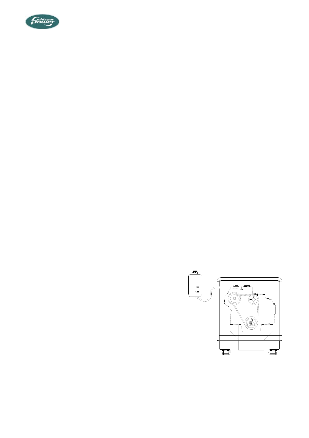
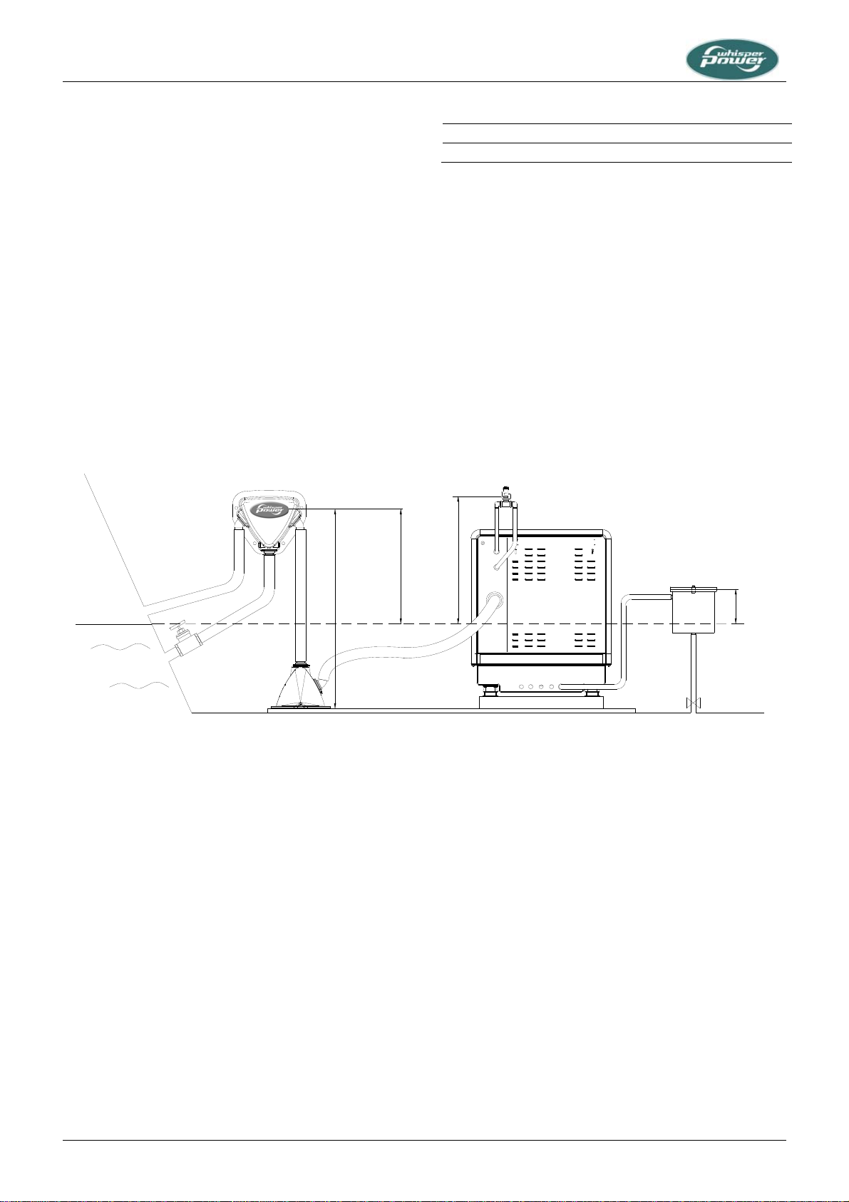
MAX.
Fig.5: Expansion tank placement
The tank has to be placed close to the generator. When it
is mounted above the top of the manifold the liquid in the
tank will be drained when the cap on the manifold is taken
off. When keel cooling or radiator cooling is applied the
system will not be pressurised. A cap without release

INSTALLATION
8October 2010 / M-SQ7 / US
valve should be applied. Refer to the special manual for
these applications.
2 RAW WATER SUPPLY
For raw water supply the following installation materials
are required: -a skin fitting - a sea cock - a water strainer -
hoses and clamps. In order to keep the suction resistance
in the line at a minimum, the sea water intake system (i.e.
sea cock, tru-hull fitting, inlet filter, etc.) must have the
following inner diameter at least:
Model Minimum inner diameter
M-SQ7 3/4" (19 mm)
The suction hose should be kept as short as possible.
Raw water plumbing should avoid bends as much as
possible.
Restriction of raw water flow, caused by kinked hoses,
undersized pipes or connections, will reduce the engine
cooling capability. This is the main cause for overheating
of an engine.
After running the generating set for the first time, check the
coolant flow rate using a stopwatch and by holding a pail
of a known volume under the wet-exhaust outlet. The flow
rate should be according to the data in the users manual.
1
2
34
5
6
7
24"
60cm
60cm
24"
60"
150cm
Max. Min.
Min.
5cm
2"
Fig. 6. Internal cooling system
1 Water level;
2 Water/exhaust separator;
3 Seacock;
4 Waterlock;
5 Air vent;
6 Water strainer;
7 Seacock.

INSTALLATION
US / M-SQ7 / October 2010 9
3 INSTALLATION OF THROUGH HULL FITTING
It is good practice for yachts to use a hull inlet fitting with
an integrated strainer (water scoop). For propulsion
engines in motorboats the water scoop is often mounted
against the sailing direction to induce more water intake
for cooling.
This should not be done in the case of a
generating set! When sailing at higher
speeds, water will be forced into the inlet and
your generating set will overflow!
Fig. 7 Installing water intake
On motorboats and on sailing boats the water scoop for a
generating set should be fitted with the opening faced
backwards to prevent water being forced in during sailing.
4 WATER STRAINER
Use an appropriate water strainer with connections of the
following dimensions:
Model Inner dimensions
M-SQ7 3/4" (19 mm)
Install the water strainer in a well accessible position,
(refer to fig. 6, ref. 6) 5 cm above the waterline.
5 SIPHON BREAKER (AIR VENT)
When the point of water injection is below the waterline,
then -when the engine is stopped -there is a risk that the
cooling water may enter the engine as a result of
siphoning. To avoid this happening, the generating set is
designed to accommodate a siphon breaker (air vent). In
the standard delivery the connections are bypassed. See
figure 8
Fig. 8: Bypassed siphon breaker connections
Hoses with the following inner diameter should be used:
Model Inner dimensions
M-SQ7 3/4" (19 mm)
If the generating set cannot be mounted such that the
bottom of the generating set is placed above the waterline,
an air vent must be installed. See figure 9.
Extend the water hose of the by-pass 60 cm above
waterline and install an air vent. Ideally, the air vent should
be mounted above the yacht keel center line (i.e. to
minimize the influence of swaying on the water intake).
Fast motorboats will lay deeper when sailing at large
speed and can cause pressure on the waterinlet. This
should be avoided to prevent fleeding the engine.
If the air vent is clogged the water hoses will
not be vented when the generating set has
stopped and water can be forced into the
engine. This leads to immediate engine
problems and eventually severe damage!
DAMAGE CAUSED BY THE INGRESS OF WATER IN
THE ENGINE IS NOT COVERED BY GUARANTEE.
SAILING DIRECTION
SAILING DIRECTION
FLOW DIRECTION
FLOW DIRECTION

INSTALLATION
10 October 2010 / M-SQ7 / US
Fig.9 siphon breaker connected
On the valve is a little hose to drain a little water that could
be spilled from the valve. This hose should go down and
may not end under water, because it should ventilate air
into the valve to break the siphoning.
OPEN
Fig 10: Wrong siphon breaker hose routing
Check the air vent at regular intervals. Open, clean and
lubricate the valve as required.
OPEN
Fig. 11 WhisperPower siphon breaker
Siphon breaker

INSTALLATION
US / M-SQ7 / October 2010 11
1.5.3 Exhaust system
Water is injected in the exhaust system of the generating
set. In this way the cooling water that has passed the heat
exchanger is mixed with the exhaust gases. Temperature
and volume of the gases are thereby reduced
considerably, so that a rubber exhaust hose can be used
and the level of noise is reduced as well.
1 STANDARD EXHAUST SYSTEM INSTALLATION
The generating set exhaust system must remain
completely independent and separate from the exhaust
system of any other engine on board. A water lock
prevents the generating set from being flooded by cooling
water and should be installed as close to the generating
set as possible. The lock must be large enough to hold the
entire water volume held in the hose from the top of the
goose neck to the water lock. The water lock must be
installed at the lowest point of the exhaust system (ref. to
fig. 12, ref. 1). The exhaust hose must have an inner
diameter of 1 5/8’ (40mm), no less, no more. The exhaust
system must be installed so that the back pressure inside
the exhaust does not exceed 0.07 bar (1psi – 70 cm
watercolumn) and total length from the genearot to the top
of the goose neck or or water/separator does not exceed
3m (10 ft.). (Refer to paragraph 5.4.3 of the users manual).
The exhaust hose descends from the capsule to the water
lock. Then the hose rises via the "goose neck" to the
through-hull exhaust outlet, situated minimum 50 mm
above the water line (ref. to fig. 12, ref. 5.) The "goose
neck" must be vertical and situated preferable along the
ship’s keel center line. If the generating set is mounted
less than 24" (60 cm) above the waterline, a "goose neck"
must be installed to prevent the engine from overflowing. It
is recommended to install an extra muffler close to the
through-hull fitting.
3
3
4
2
5
6
A
Minimal 24"60cm
Maximal 60"150cm
2" 5cm
B
HOSEROUTEA- BMAX. 10ft (3m)
Fig. 12: Standard exhaust system
1 Exhaust water lock;
2 Exhaust outlet muffler;
3 Exhaust line Ø 1 5/8” (40 mm);
4 Goose neck
5 Through-hull exhaust outlet Ø 1 5/8” (40 mm);
6 Water level.
1

INSTALLATION
12 October 2010 / M-SQ7 / US
1 Water level 3 Seacock
2 Water/exhaust separator 4 Waterlock
Figure 13: Super silent exhaust system
Figure 14: Only after the exhaust / water separator the exhaust hose may have a length of over 25 ft (7.5 meter)
MAX. 10CM (4")
MIN. 60CM (24")
MAX. 150CM (60")
MIN. 3CM (1,2")
1
2
34
Ø 1
5
/8”
40 mm
Ø 1
5
/8”
40 mm
Ø 1
5
/8”
40 mm B
A
Maximum length: 30ft (10 m)
Ø 1
5
/8” (40 mm)
Ø 1
5
/8”
(40 mm)
Ø 1
5
/8” (40 mm)

INSTALLATION
US / M-SQ7 / October 2010 13
2 SUPER SILENT" EXHAUST SYSTEM
See figure 13. In order to reduce the noise level of the
generating set to a minimum, an option to reduce the
exhaust noise further (especially exhaust water splashing)
is an exhaust/water separator. The exhaust/water
separator allows the cooling water to be ejected through a
line separate from the exhaust fumes and also functions
as a goose neck to prevent water from flooding the engine.
If the exhaust/water separator is mounted more than 24”
(60 cm) above the water level an additional goose neck is
not required.
If the through-hull exhaust outlet has to be mounted far
from the generating set (total length of the exhaust piping
from generator to top of goose neck (water separator) is
more than 10 ft (3 m.)), an exhaust/water separator must
definitely be installed (see figure 14). The sea water from
the separator must then run down along the shortest
possible path to the through-hull outlet.
Only after the exhaust/water separator the exhaust hose
may have a length of over 25 ft (7.5 m) if the exhaust hose
diameter is also increased from 1 5/8” (40 mm) to 2” (51
mm) in order to reduce the back pressure (ref. to fig. 14)
However watertraps should be avoided as the fumes still
contains water and this should not accumulate in bents
(refer to fig 15 and 16). An additional outlet exhaust
muffler close to the hull outlet will help further to reduce
noise emission (see figure 12, ref.2).
Figure 15: Water trap in exhaust system
Figure 16: Water will collect in the hanging bend of the exhaust gas hose and will cause back pressure.
OK!
WRONG
OK! WRONG!

INSTALLATION
14 October 2010 / M-SQ7 / US
If the generating set and the exhaust system have been
installed correctly, neighbouring boats will not be disturbed
by generating set noise. With the "super silent" exhaust
system, generating set noises are almost inaudible. For
optimal noise reduction, the sea water outlet from the
exhaust/water separator (centre outlet on the unit) should
be installed below the water level to eliminate noisy
splashing of the effluent sea water.
The through-hull outlet for the exhaust fumes should not
direct the fumes directly toward the water surface as this
will cause excessive noise (ref. to fig. 17).
Do not direct the outlet directly toward the
water surface.
Fig. 17. Outlet direction
1.5.4 Digital Diesel Control system (12 Volt)
1 DIGITAL DIESEL CONTROL SYSTEM
The electrical control system is standard in 12 Volt with
negative earth. Non- earth return is available as an option
for aluminium vessels to prevent corrosion.
All electrical wiring has been prepared on the generating
set to the control panel prior to despatch from the factory.
The engine is controlled by a very advanced
microprocessor based system: Digital Diesel Control.
The “black box” containing the microprocessor is located
on top of the alternator.
A local control panel is on the generating set.
Remote control
A remote control panel also containing a microprocessor is
in the delivery. A 45 feet (15 meter) intermediate 8-pole
communication cable is in the standard supply as well
(refer to fig. 18). If necessary an optional longer (up to
100ft - 30m) intermediate cable can be connected if the
standard length does not suit the required distance. When
a longer distance than 100ft - 30m is required, consult the
WhisperPower service department for advice.
Fig. 18 Remote control cable
One can mount the control panel after drilling a hole in the
dashboard using the plastic cover. Refer to the
dimensional drawing in paragraph 3.5. The panel without
the plastic cover fits the Mastervision modular panel
system.
More remote control panels (slave panels) can be put in
parallel by using the modular connectors on the back of
the units. As a slave one can use the same panel offering
all functions again. It is also possible to use an old or new
type slave panel only to start and stop the generator.
Old type remote panels and system panels can be
connected by means of the green connector.
Pay attention to the colour codes as indicated in fig. 19
when fitting cable to the green connector. Some software
versions in old system panels (supplied before May 2004)
could conflict with the software in the DDC and an update
of the software of the system panel could be necessary.
When this is the case consult to the WhisperPower service
department for advice.
When using the factory settings, installation is very simple:
just plug the remote cable into the remote and the
generator is ready to use. Refer to fig. 19.
OK !
WRONG !

INSTALLATION
US / M-SQ7 / October 2010 15
WIRINGCOLOURS
RED
GREEN
BROWN
YELLOW
PINK
PURPLE
BLUE
WHITE
GREY/ PINK
GREY
RED/BLUE
BLACK
MAX. 150 mA
WARNING RELAY
REMOTE CABLE
REMOTE CABLE
2
1
5
4
3
8
7
6
11
10
9
12
SENSE BAT. 2
121110987654321
Whisper Remote Panel
WRP/2
J3
Fig. 19 Remote box terminals
Acoustic alarm or warning lamp
One can connect an external max.150 mA relay to
generate an acoustic warning or applying a warning lamp
etc. Be aware of polarity as some relays has a diode
inside and should be connected plus to plus en minus to
minus as indicated. Refer to fig. 19.
Connection for emergency stop / fire alarm switch
Fig. 20: Connection for emergency stop / fire alarm switch
To connect an emergency stop button or to stop the
generator automatically in case of a fire alarm, you can
use the bypass connection between fastons J7 and J18 on
the backside of the local control panel. See fig. 22. To do
so, remove this bypass connection and then replace it by
an emergency switch or a potential free fire alarm switch
with normally closed contacts
Automatic start/stop
WhisperPower cannot be held responsible for
damage caused by the unattended running
generator using the auto-start/stop mode or
interval mode
Using the auto-start/stop (interval) mode the
generator can start unexpectedly. When
working on the electrical system, the 3 Amp
fuse must be removed from the control panel
and the battery plus cable must be removed
from the battery.
In the delivery are warning stickers to stick on
several parts of the electric installation
(transfer switch, distribution box, etc.) to warn
for automatic start)
The WhisperPower Digital Diesel Control system offers
several options for automatic starting and stopping.
Access to this menu and other menus could be blocked.
For blocking and setting up this options refer to the
APPENDIX of the DDC users manual.
One of these options is to monitor a second battery (not
being the starter battery) to start the generator
automatically when the voltage of this battery drops below
a certain setting.
Other names for this second battery are “auxiliary battery”,
“service battery”, ”users battery” or “consumers battery”.
We will refer to this battery as “the second battery”(BAT2).
In some menus the starter battery could be indicated as
“the first battery” (BAT1).
A sense wire to monitor the second battery should be
connected (attention polarity!) to the connector on the
back of the remote panel. Refer to fig. 19. The sense wires
must be connected directly on the second battery before a
main switch and be protected by a 3 Amps fuse.
(Monitoring the generator starter battery does not require
an extra sense connection).
Settings
When one want to apply other settings than the factory
settings refer to the DDC users manual, especially to the
APPENDIX.
Remove bypass
between J7 - J18
Normal operation
Alarm / emergency
local control panel
(rear view)

INSTALLATION
16 October 2010 / M-SQ7 / US
2 STARTER BATTERY
For starting, the Whisper requires a 12V starter battery
with the following capacity:
Model Minimum capacity
M-SQ7 60Ah
The generating set can be connected with the main engine
battery or have its own battery.
We strongly recommend the use of a separate battery for
the generating set and to keep the wiring system for the
propulsion engine and the domestic DC supply system
completely separate and individually connected to
separate batteries.
230VAC
IVO12/10
AB
12V
+-
Fig. 21 Starter battery
However, the negative of all the batteries on the vessel
should be interconnected (when on earth) to avoid
difference in the voltage level of the earth on different
places causing trouble to electronic devices which might
be in the system.
The above recommendation is not valid for ships having
the starter battery of the propulsion engine or other
auxiliary equipment positive grounded. When this is the
case an expert should be consulted.
A battery switch may be used to interrupt the positive
connection.
The starter battery is charged by the alternator on the
engine. An additional battery charger will help to keep the
battery in good condition when the generating set is not
used. A battery charger is not included in the standard
supply. A high efficiency battery charging unit can be
ordered from WhisperPower which is able to charge both
the ship’s main battery and the starter battery. Also a small
charger can be used to charge the starter battery only,
such as the IVO SMART 12/10. A battery switch and a
charger are included in the battery installation kits, art. no.
50230210 (70Ah) or 50230220 (160Ah).
3 OTHER RECOMMENDATIONS AND WARNINGS
The battery should be secured for seagoing conditions and
the terminals should be insulated. For extra safety the
battery can be enclosed in a wooden, plastic, fiberglas etc.
(non metal) box. Even when the earth return system is
applied a negative battery cable should be used and the
vessel should not to be used as a conductor.
The battery cables are supplied in a standard length of 1.5
m, if longer cables are required a larger cross sectional
area should be considered to compensate for voltage
reduction.
When two batteries are used in series to provide a 24 Volt
supply system, never take off 12 Volt (starting) power from
one of these batteries. This will result in severe damage to
both batteries within a short time.
Disconnect the battery leads if electrical welding is to be
carried out, otherwise damage will be caused to the diodes
of the alternator.
As explosive hydrogen gases may be
discharged during charging, the battery
should be located in a well ventilated room.
Ensure that the supplied battery cable
connectors are properly fitted and never
remove during or shortly after charging as
sparking can occur, which may ignite the
hydrogen gasses.
1.5.5 AC power system (120 - 240 Volt)
Before working (installation) on the system
read the sections on safety in the users
manual.
Be sure that all electrical installations (including all safety
systems) comply with all required regulations of the local
authorities. All electrical safety/shutdown and circuit
breaking systems have to be installed onboard as the
generating set itself cannot be equipped with such
equipment for every possible variation.
The vessel’s power supply system should be suitable and
safe for the AC voltage which is applied and the power
that will be generated. Special attention has to be paid on
dividing the system in branches which are fused
individually.
It is absolutely essential that each and every circuit in the
on-board electrical system is properly installed by a
qualified electrician.

INSTALLATION
US / M-SQ7 / October 2010 17
1 FUSE
An output fuse (from the generating set to the system)
should be installed to protect the installed electrical
system. The following maximum single phase output
current applies:
Model Maximum single phase
output current
120V 240V
M-SQ7 58 Amps 29 Amps
The fuses must be of the slow reacting type. For electrical
motors connected to the system, a motor protection switch
must be installed
2 GROUNDING
With the U.S.A. models neutral of the AC
alternator is grounded. The housing of the
alternator and all other metal parts are
grounded as well.
The connection between “neutral” and “ground” is
necessary as part of a insulation failure protection system
as commonly used in the U.S.A.
WARNING
In all situations the transfer switches between
shore, inverter and generator should switch all
connections, the phase line (L) as wel as
neutral (N). Off course this is the case when
using a Masterswitch.
For safety reasons connect the main ships ground to
negative point of the generating set start battery. When a
ungrounded DC system or positive grounded DC system is
applied the battery negative should not be connected to
the main ships ground.
3 CABLE
For the power cable we recommend the use of 4 wire oil
resistant cable with a sufficient cross sectional area. One
wire for earth is included. For long cables it is
recommended to apply cables with a larger cross section
(refer to ISO 13297 annex A).
4 TRANSFER SWITCH
A power source selector switch much be installed between
the generating set and the ship’s electrical supply system.
This switch must ensure that all AC consumers can be
switched off at once. This switch should also be installed
to keep the generating set and shore (grid) power systems
separate.
Transfer switches - to switch over from shore to ship or
from generating set to inverter - should be well designed to
switch over all wires including neutral (and not only phases
or line) and there should be provisions with the aid of
timers to prevent relays from clattering.
WhisperPower recommends the installation of a
Masterswitch as the power source selector. This works
automatically when the generating set is not running the
input remains in the shore position and as soon as the
generating set is running the Masterswitch switches
automatically after 10 seconds delay time over to the
generating set position.

INSTALLATION SPECIFICATIONS
18 October 2010 / M-SQ7 / US
2 INSTALLATION SPECIFICATIONS
2.1 GENERAL
1 Mount the generating set directly, without additional
vibration dampers, on a solid surface.
2 Connect the (sea) water inlet to the strainer.
3 Connect exhaust system.
4 Connect a siphon breaker or ‘air vent’ into the cooling
circuit, if necessary.
5 Connect ‘fuel supply line’ to the water separator/ fuel
filter.
6 Connect ‘fuel return line’ to the fuel tank.
7 Connect remote panel (just plug in).
8 Connect the AC cable from the AC box to the power
source selector (or Masterswitch).
9 Connect plus and minus from the 12V starter battery
to the battery cables.
10 Install a WhisperPower battery charger. (optional)
2.2 COMMISSION TABLE
1 Check if a siphon breaker (air vent) is necessary and
has been installed
2 Open the seawater inlet valve and check all water
connections. Check if the strainer is installed on or
just above the seawater level.
3 Check if the exhaust system is properly installed.
Check maximum length of exhaust hose, diameter of
exhaust hose, position of the water lock, maximum lift.
Also check the minimum required height of 60 cm
above sea level of the exhaust loop (goose neck).
4 Open the seawater outlet valve and check all water
connections.
5 Check the AC cables and the grounding.
6 Check if an AC breaker is installed before or after the
power source selector. When there is only a circuit
breaker, use it to disconnect the generating set from
the grid.
7 Check all DC connections, check if the battery switch/
circuit breaker is closed.
8 Open the fuel valve. Check if there are no air leaks in
the fuel supply line, and check if the lift of the fuel is
less than 1 meter. Check if there is no air in the water
fuel separator.
9 Check if the air intake in the canopy is not blocked.
10 Check the oil level and colour of the oil. Check the
coolant level
11 To bleed the fuel system, push the “Start” button on
the local control (not on the remote panel) and hold at
least 5 seconds and as long as necessary to bleed
the system.
12 Start the engine by pushing the start button
13 Check when the generating set is running, the delay
of 5 to 10 seconds in the power source selector
transfer.
14 Check voltage and frequency under ‘no load’
conditions.
15 Check voltage and frequency under ‘full load’
conditions.
16 Check if the battery charger of the generating set is
working (max. 14.5 Volt).
17 Close the sound shield and check the noise level.
18 Stop the generating set and check the engine again
for leakages of oil, fuel or water.
Installation checklist available on our website:
www.whisperpower.eu.
Commissioning form available on our website:
www.whisperpower.eu.

INSTALLATION SPECIFICATIONS
US / M-SQ7 / October 2010 19
2.3 INSTALLATION SPECIFICATIONS
TECHNICAL DATA
Model M-SQ7
Dimensions lxwxh. 31.7 x 20.7 x 22.8’ (80.5 x 52.5 x 58.0 cm)
Weight including sound shield 530 Lbs (240 kg) including sound shield
Max. operation angle 25°
Remote panel 15 m cable Digital Diesel Control System
Battery capacity min. 12V / 60Ah
Fuel consumption 0.53 – 1.2 US gph = 1,5 – 4 litre/hour (load dependent)
Model fuel pump Electrical driven 12V
Max lift fuel pump 3ft (1m)
Cooling Indirect
Cooling pump WhisperPower self priming raw water impeller pump, PTO driven
Model cooling pump M
Minimum water supply 3 – 4 US gpmin (9-15 l/min)
Alternator synchronous brushless, maintenance free water cooled
Voltage regulation capacitor + AVR
Output power at 60Hz, power factor cos phi = 1 7 kW
Battery charger alternator including regulator (40 Amps)
2.4 SPECIFICATION OF THE ACCESSORIES
Model: M-SQ7
Water scoop 3/4” = 19 mm
Inlet valve 3/4” in / 19 mm out
Water strainer 3/4” = 19 mm in / 3/4” = 19 mm out
Air vent 3/4” = 19 mm
Inlet suction hose 3/4” = 19 mm
Fuel filter/water separator 30 micron
Fuel inlet and return 5/16” 8 mm
Exhaust hose Ø 1 5/8” (40 mm) inner
Water lock Ø 1 5/8” (40 mm)
Water/gas separator Ø 1 5/8” (40 mm)
Anti shock mounts Included
Battery charger (optional) IVO SMART 12/10; 12V / 10 Amps

INSTALLATION SPECIFICATIONS
20 October 2010 / M-SQ7 / US
2.5 INSTALLATION MATERIALS
WATER INLET KIT 3/4” (20 mm)
no qty article no description dimensions
1 1 50230052 Intake strainer 3/4
2 1 50230042 Lever operated ball valve FF 3/4
3 1 50221004 Male hose connection 3/4x20
4 4 50221502 Hose clamps 19-29 mm
5 3 50220056 Outboard cooling water hose 20x28 mm
6 2 50221007 Male hose connection 1/2x20
7 1 50230060 Nickel plated brass intake strainer 1/2
8 1 50230067 Mounting bracket waterstrainer
TOTAL 50230211 WATER INLET KIT 3/4” (20 mm)
AIR VENT KIT 3/4” (20 mm)
no qty article no description dimensions
4 7 50221502 Hose clamps 19-29 mm
5 3 50220056 Outboard cooling water hose 20x28 mm
11 2 50221031 Bend male type with hose connection 1/2x20
12 1 50221042 TEE fittings 1/2
13 1 50230001 Syphon breaker valve 1/2
14 1 50221001 Male hose connection 3/8x13
15 1 50221521 Hose clamps 12-20 mm
16 1,5 50220055 Outboard cooling water hose 12x18.2 mm
TOTAL 50230212 AIR VENT KIT 3/4” (20 mm)
This manual suits for next models
1
Table of contents
Other WhisperPower Marine Equipment manuals