Qlight STDEL-USB User manual

PB 1
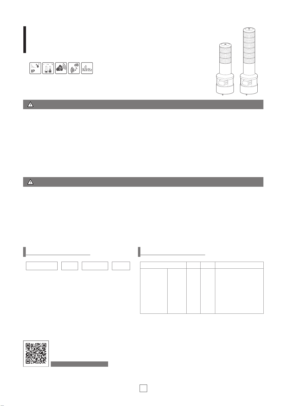
USB LED Tower Light with Built-in Sounder
STDEL-USB
5030
54
105
HORN
Please scan the QR code
for more
detailed product information.
www.qlight.com
STDEL-USB-WS
-3-24 -RAG
[Model number] [Layer] [Voltage] [Color]
| | | |
• STDEL-USB-WS
• STDEL-USB-WM
• STDEL-USB-WA
•
Layer
1-1
•
Layer
2-2
•
Layer
3-3
•
Layer
4-4
•
Layer
5-5
• 12-DC12V
• 24-DC24V
• 110-AC110V
• 220-AC220V
R-Red
A-Amber
G-Green
B-Blue
W-White
• Protection rating : IP54
• Ambient operating temperature : -30°C to + 50°C
Model number
Layer
Certi¿cate
Color
STDEL-USB-WS
STDEL-USB-WM
STDEL-USB-WA
5 Warning
sounds
5 Melodies
5 Alarms
•
Layer
1
•
Layer
2
•
Layer
3
•
Layer
4
•
Layer
5
-
Layer1 :R-Red
Layer2: R-Red G-Green
Layer3: R-Red A-Amber
G-Green
Layer4 : R-Red A-Amber
G-Green B-Blue
Layer5: R-Red A-Amber
G-Green B-Blue W-White
Product SpecicationsOrdering Specications
Thank you for purchasing Qlight’s products. Please read this user manual carefully
prior to installation and operation to ensure safe and correct use.
Precautions for Safety
Failure to follow the instructions below may cause a loss of life or serious physical injury.
1. Please remove any objects that can interrupt ventilation around the product.
2. Please turn o-• the power of the product immediately if it fails to operate properly.
3. Carefully wire the product according to each product’s speci¿cation.
4. Please be careful in preventing chemicals such as thinner, benzene, etc. in contact with the surface of the product.
5. Do not apply excessive force/impact to the product.
6. Failure to follow any of the instructions above may cause malfunction or damage to the product, ¿re, and electric shock.
Precautions for Correct Use
Failure to follow the proper instructions may cause damage to property, the product, or malfunction of the product
that would void the warranty.
1. During wiring or maintenance, please completely turn o-• the power of the product. (Failure to follow this may lead to an electric shock.)
2. Do not install the product in locations that subjects it to excessive dust or water other than the conditions designated by the IP protection
ratings indicated for each product. (Failure to follow these instructions may cause a ¿re to the product, electric shock, physical injury,
malfunction or damage to the product.)
3. Do not alter or repair this product. If maintenance or repair service is required, please contact your local Qlight contact point. (Failure to
follow these instructions may lead to ¿re, electric shock, or product damage.)
4. Please apply the correct voltage to the product. (Failure to follow these instructions may lead to ¿re, electric shock, or product damage.)
5. When the product is applied to a condition that may impact lives or property, please make sure to have a double safety device. (Failure to
follow this may cause damage to property, ¿re, electric shock and loss of life.)

2 3
STDEL-USB
USB CONNECTOR
USB POWER CONNECTOR
Dimensions
(Units : mm)
Fuse
USB POWER
CONNECTOR
USB CONNECTOR
STDEL-USB
1
2
3
4
5
Black(BK)
White(W)
Gray(GR)
Power
1. Please connect USB Tower Lamp and PC as above ¿gure <How to connect with PC>
2. Please download test program(USB.zip) from Qlight website or blog.qlight.com
3. The downloaded sample program will be saved as “USB Test Program.zip”.
When you unzip the ¿le, there will be a ¿le with the names below.
Test program Required library for test program
※
When developing the program, please download and refer to the ¿le “manual and library”(sample programs and manuals
for developers).
4. When you run the “QLight lamptest_usb.exe”¿le, a test programs will show up as above.
Products sound options are classi¿ed as WS / WA / WM / BZ. The product will only play the sound option selected when
the order was placed.
① Lamp Control ② Sound Selection ④ Index
③ Sound Group Selection
Test Instructions
<For Connecting Method with pc> <Test program>
• External power line - UL1015 AWG18(0.75sq)×2C 400mm
• USB Cable : Connect both USB connector and USB power
connector to PC
• Connect both USB power connector and USB signal control
connector that are connected to each other to USB ports of a PC.
• Product does not run in case of USB power connector connection only.
USB Cable Wiring Instructions
15
112
12
40
L
152
PCD 70
360°/3-M5 BOLT
LAYER
1
2
3
4
5
L
284
324
364
404
444
Ø8 CABLE ENTRY
Ø80
Ø119
USB CONNECTOR
USB POWER CONNECTOR

2 3
Cover
(ABS)
Long bolt
Lens(AS)
Housing (ABS)
USB CONNECTOR
USB POWER CONNECTOR
Resonator(Material:ABS)
3-Ø6 HOLES
Ø15 CABLE ENTRY
PCD 70
Mounting Hole SpecicationsParts Denition
① Machine holes on the mounting surface referring to the
diagram below.
② Remove the ange nuts from bolts and place the product
through the mounting surface holes.
③ Fasten the ange nuts on the opposite side of the mount-
ing surface until the product is tightened securely.
■ How to use program
Article Detailed speci¿cation
① Lamp control
- ON: Lamp turns on when the button is clicked
- ON/OFF: Lamp ashes when the button is clicked
- OFF: Lamp turns o-• when the button is clicked
② Sound selection
- 1ch-5ch: Has 5 sounds per model, turns on the chosen sound
- Click “Sound o-•” button to turn o-• the sound
③ Sound group selection
- WS : 5 warning sounds(mono)
- WP : 5 special warning sounds(mono)
- WM(1) : 5 Melodies(mono)
- WA(1) : 5 alarms(mono)
- WB : Software Buzzer 5 sounds(speaker type)
- Buzzer : 5 Buzzer sounds
④ Index - You can connect up to a maximum of 4 USB Tower lights per PC
- Must be controlled by selecting Index0 - Index3 for controlling the USB tower light. The default is set to Index0
Volume Adjustment
• The volume output of this product is adjustable.
•
Turn the volume dial clockwise
to increase the volume, and turn counter clockwise to decrease
the volume.
• There will be no sound when the dial is put at MIN.
Volume Dial
VOL.
MIN.MAX.

4
Ø22
PCD60~70
PCD50
PCD85
Ø10 CABLE ENTRY
360°/ 3-
Ø5.5 HOLES
6-Ø5.5 HOLES
4-Ø5.5 HOLES
26.511.5
115
70
90
65
Ø22
PCD60~70
PCD50
PCD85
Ø10 CABLE ENTRY
360°/ 3-
Ø5.5 HOLES
6-Ø5.5 HOLES
4-Ø5.5 HOLES
26.511.5
117
70
94
69
How to Change Lens Kit
②
③
①
Mounting Accessories (Sold Separately)
• Please refer to the dimensions below for installati on of mounting brackets
Installation Environment and Protection Rating
• This product is designed for use with protection rating of IP54.
• If the product is installed in locations that subject it to excessive dust or water other than the designated IP protection rating
indicated(IP54), it may cause malfunction or damage to the product.
• In case of outdoor applications, install the product in the upright position. Do not install the product horizontal or upside-
down positions where water can potentially penetrate into the product and impact it’s operation.
• For further information, please visit our website (www.qlight.com).
Dimensions
STDEL-USB
SWP125 SWM125
• When rearranging or replacing the lens kits, please be aware of the
contact point ①and the connector pin ②marked in the diagram on
the left.
•
Press down to assemble the lens kits while making sure that connecto
r
pin ②and connector ③aligns correctly.
• Please make sure that the rubber spacer placed on the top of each
lens kit is tightly secured to the bottom of the other lens kit.
※Caution when lens kit
•
Lens kits are connected with connector pins each other. Bad connec-
tion may be experienced when the connector pins are touched with a
foreign substance.
•
If the lens kits are not turned on or not ashed after lens kits replace-
ment, please make sure status of lens kit connection.

Product installation direction
■ Install the product in accordance with the manual. Otherwise rainwater or moisture may penetrate into the product.
ㆍ ELECTRONIC SOUNDER/SIGNAL HORN
Sounder part shall not be facing the sky.
ㆍBEACON/SIGNALING LIGHT
Power cord inlet part shall not be facing the sky.
ㆍSIGNAL TOWER LIGHTS
ㆍHEAVY-DUTY & EXPLOSION PROOF SIGNALINGS
※For products with a protection rating of less than IPX4, please install it vertically.

MEMO

MEMO

Head O-ce | Suite #1510, STX-V Tower, 128 Gasan digital 1-ro, Geumcheon-gu, Seoul, Korea
Tel. +82-2-2679-6152(Toll free. +82-80-328-2222) Fax. +82-2-2679-6154
Factory | 185-25, Mukbang-ro, Sangdong-myeon, Gimhae-si, Gyeongsangnamdo, Korea Tel. +82-55-328-1111(Toll free. +82-80-328-1111)
Qlight Overseas Sales Dept |
704 Nakdong-daero, Sasang-gu, Busan, Korea(Eomgung-Dong) Tel : +82-51-620-4100
Qlight Public Relations & Marketing Team O-ce | 704 Nakdong-daero, Sasang-gu, Busan, Korea(Eomgung-Dong) Tel. +82-51-245-0017
China Factory/ Shanghai Sales O-ce | #Room 333 Building B, #11, Lane 450, Zhenda Road, Baoshan District, Shanghai, China
Tel. +86
-
21
-
6651
-
7100 Fax. +86
-
21
-
6315
-
3929
China Factory Site 2 (Qidong) | #33, Haiyan Road, Qidong High-tech Industrial Development Zone, Qidong, Jiangsu Province, China
Tel +86
-
513
-
8384
-
9999 Fax +86
-
513
-
8384
-
9910
Product Operation Inquiry / Customer Support +82-51-620-4100
You can expect prompt service if you have exact information such as model name, symptom, telephone number and address.
※ALL PRODUCT, PRODUCT SPECIFICATIONS AND DATA ARE SUBJECT TO CHANGE WITHOUT NOTICE TO IMPROVE
RELIABILITY, FUNCTION OR DESIGN OR OTHERWISE.
Head office : Suite #1510, STX-V Tower, 128 Gasan digital 1-ro, Geumcheon-gu, Seoul, Korea ( Postal Code : 08507)
Factory : 185-25, Mukbang-Ro, Sangdong-Myeon, Gimhae-Si, Gyeongsangnam-Do, Korea ( Postal Code : 50805)
For your safety
Speci¿cation and dimensions listed in this catalogue subject to change without notice for product quality improvement.
The newest product information is available on our website.(www.qlight.com)
Please read the instruction manual attached to the product carefully before installation and use.
www.qlight.com
EN - STDEL-USB - 2401A
This manual suits for next models
3
Table of contents
Other Qlight Marine Equipment manuals
Popular Marine Equipment manuals by other brands

Teledyne
Teledyne RIVERRAY Deployment guide

Pfannenberg
Pfannenberg DS10-SIL Instruction Manual/Safety Manual

Teledyne
Teledyne Everywhereyoulook WAYFINDER manual

Furuno
Furuno FMV-603 Operator's manual

Vetus
Vetus TMWQ Installation instructions and operation manual

MarkSetBot
MarkSetBot MarkSetBot Setup guide

LXNAV
LXNAV SmartShunt 100A installation manual

INIM
INIM IVY Series Installation and programming manual

Kongsberg
Kongsberg Simrad IS12 Service manual

Skipper
Skipper ESN200 Operation and installation manual

Transas
Transas NAVI-SAILOR 4100 ECDIS installation guide

Selden
Selden Furlex 404TD Manual and spare parts list