CLA-VAL X117E Owner's manual

X117E Contact-Less Valve Position Transmitter
X117E
MODEL
INSTALLATION / OPERATION / MAINTENANCE
X117E Contact-Less Valve Position Transmitter
Thank you for purchasing a Cla-Val Model X117E Contact-less
Valve Position Transmitter. With proper maintenance, the X117E
will perform indefinitely and provide very accurate and reliable
valve control. It is built with the latest technology utilizing the high-
est quality components. The X117E is a unique electronic contact-
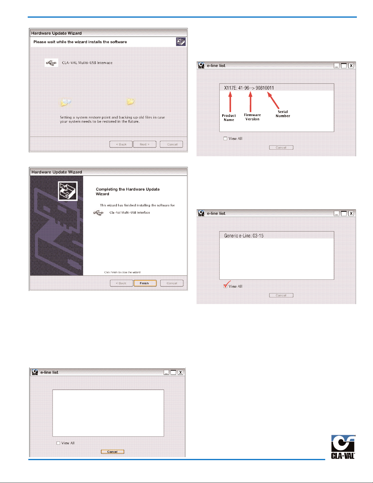
less valve positon indicator. Its software allows easy programma-
ble control features. The graphic interface is user friendly and
offers an easy way to calibrate your automatic control valves.
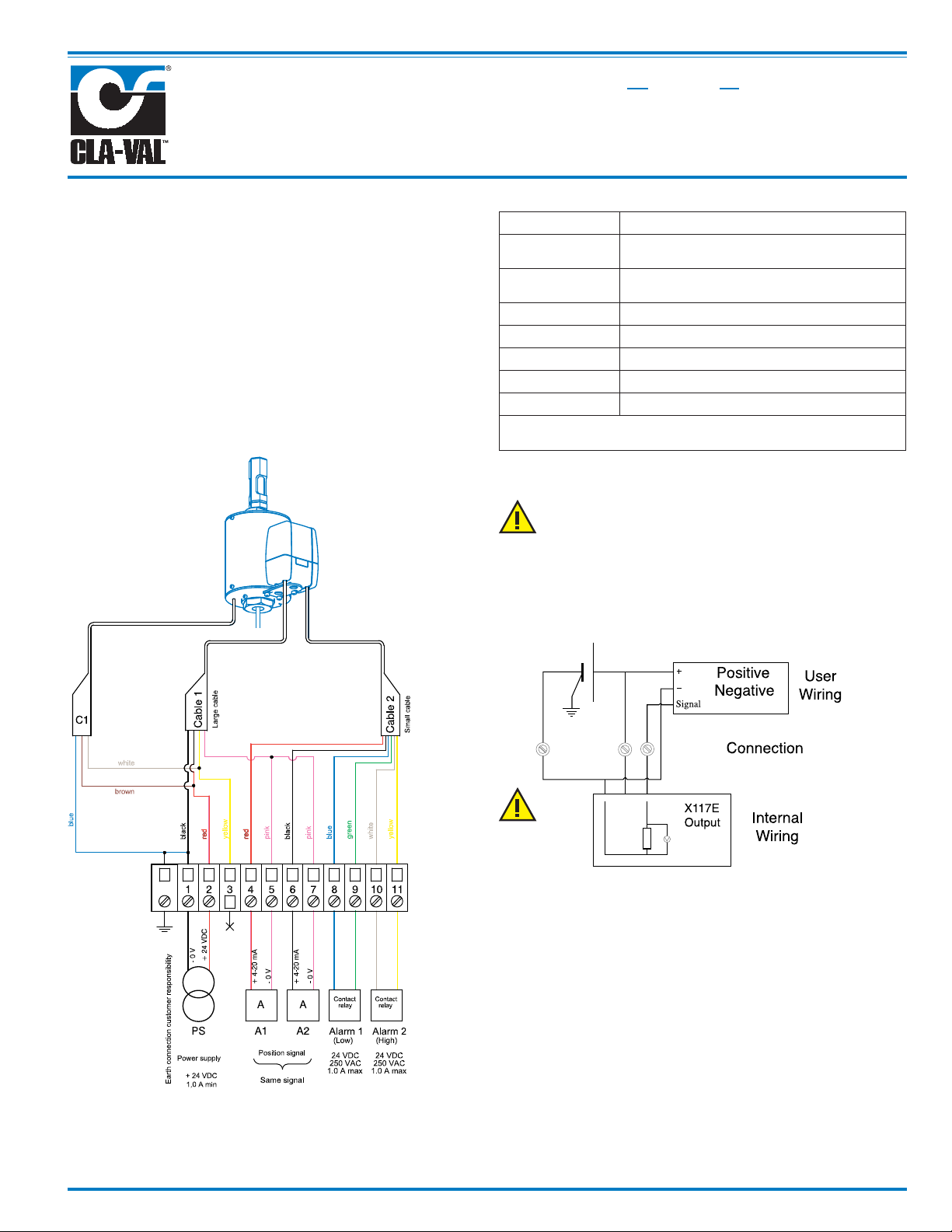
Wiring Diagram
Technical Data
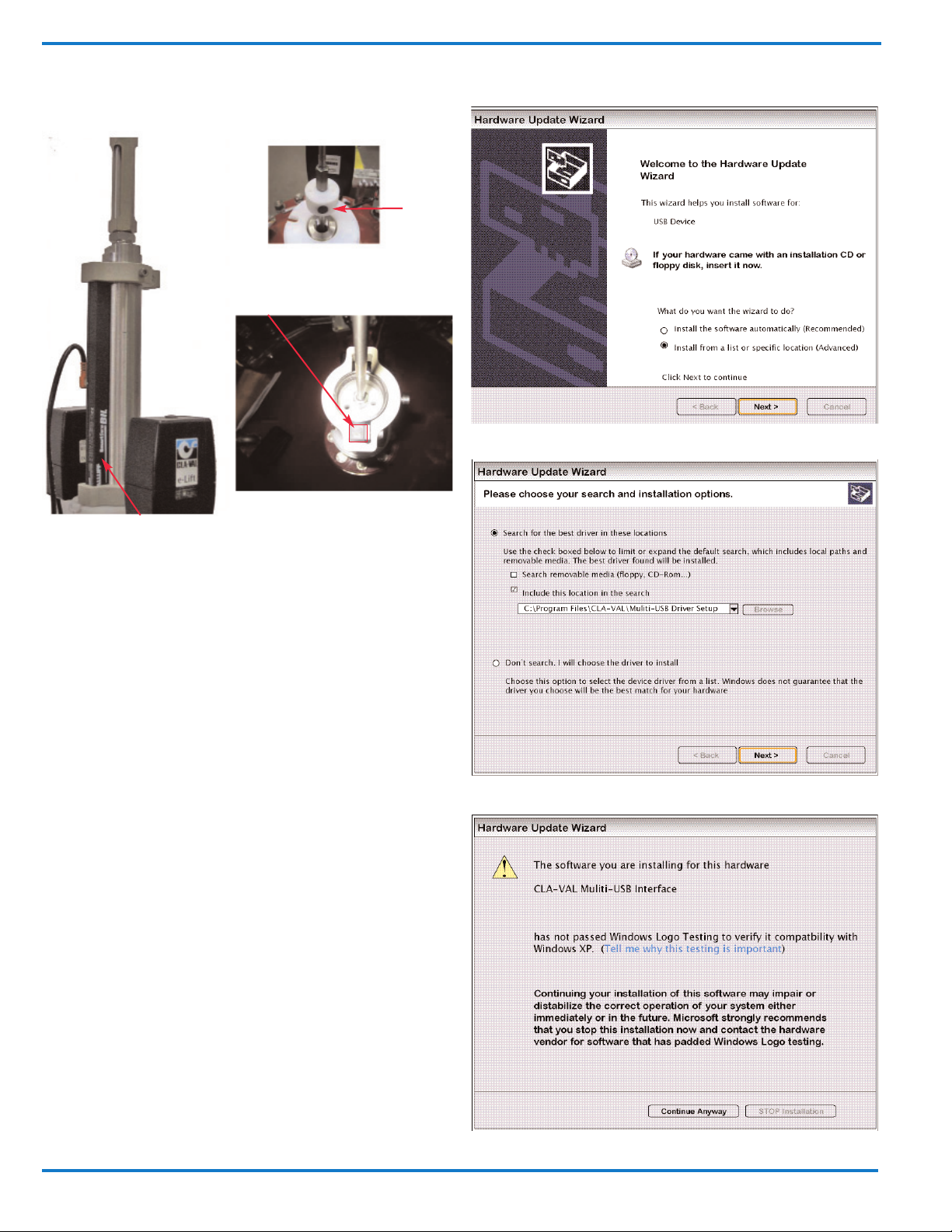
The X117E uses a magnetic sensor, take care to keep the installa-
tion free of any magnetic fields (transformers, motors, high
power supply, ect...)
Connection
output
Installation Instructions
1) All installation, adjustment and maintenance should be
carried out by a competent electrician.
2) Do not exceed the maximum ratings given in the
specifications and printed on label.
3) The electrical connections should be made as described in
the userʼs manual.
4) Before any maintenance operation the main power should
be turned off
Do not attempt to open the product
as this will invalidate the warranty!
Terminal strip not
supplied for
Illustration
purpose only
Sensor: Contact-less magnet sensor
Power: 24 VDC +/- 10%, min. 20 mA, normal 40
mA, max. 60 mA
(*)Outputs 4-20 ma, not isolated, protected, same com-
mon, output charge ≤ 500 Ω
Accuracy: < 1% Full scale
Operating range: (-20˚C to +65˚C)
Protection: IP68
Interface: Plug & Play / NT / 2000 / XP / Vista
Consumption: 6 Watt maximum
(*) The input dry contact and analogue output has the same
common or earth but are not individually isolated.
Power Supply 24 VDC
+ 24V
0V
Black Red Output
Charge
Max. 500

Page 2
Assembly Details
Firmware update (internal software)
Before the Firmware update, save your program to your PC.
1) Connect the USB cable to the USB connection of your PC.
2) Connect the X117E to the USB cable.
3) Select “Read Parameters” to read X117E settings and
record output parameters.
4) Select “Firmware update” in “Parameters”.
5) Open the corresponding file ”.hex”.
6) Select “Read Parameters” to check that the Firmware is
updated.
USB Driver Installation or Updating USB Driver or
Install on Another USB Port
When you connect the X177E for the first time, your PC will detect
it and request a driver.
To update your USB driver, please follow the procedure below.
Install the software “Multi-USB Driver Setup” Download multi-USB
software from the Cla-Val web site: www.cla-val.com
Connect the USB cable to the laptop.
Select: "Install from a list or specific location".
Browse to file: C\Program Files\CLA-VAL\Multi-USB Driver Setup.
Microsoft validation presss “Continue Anyway”
Internal view
Mounting direction of the sensor
Sensor
Magnet
Mounting direction of Magnet
During mounting, take care that
the magnetic sensor and the face
of the magnet are parallel.

Installation
Installation complete,
Click finish.
Configuration Mode
To launch X117E Contact-less Valve Position Transmitter software
when not connected to the laptop, the e-line list (which allows the
multi connection of e-Line products) is empty (see picture below),
click “Cancel”.
If connected to one or more X117E or another e-line product,
click on "View All" and select the e-Lift you would like to commu-
nicate with from the list (see picture below) then click once on left
mouse button.
Product name, Firmware version and serial number are displayed.
If your e-Line product isn’t updated with the “Multi connection”
version, the e-Line list stays empty. Click on "View All", the
e-Line product appears with name "Generic e-Line" (see picture
below), then click once on left mouse button on this line to
communicate with the product.
For the name and serial number of this product to appear, a
Firmware update is necessary (see chapter 3.6).
Page 3

How to Calibrate the X117E
Page 4
Calibration Display
1 Connect to 24 VDC power supply.
2 Connect the USB cable to your PC.
3 Connect your PC to the X117E with the USB cable.
4 Start the X117E Cla-Val software.
5 Enter the valve’s lift, and then click on "Lift". The valve opening information is now ready in inches or mm.
6 Click on "Program" (1).
7 Close the valve and click on "Valve closed" (reference point) .
8 Open the valve (manually, with air, ect...) and click on "Valve open".
9 Click on "Read parameters" (2).
By default, these alarms are set to 10% Low Level, 90% High Level and Hysteresis Alarm Level 2%. To
modify this adjustment, see Adjustement of Alarms
After a setting modification, you must click on "Read parameters” (2) in order to complete the
modification!

1 Close the valve then click on "Valve closed" .
2 Open the valve as much as you can.
3 Calculate the opening percentage reached..
4 Enter this percentage into the field "Valve % opened".
5 Click on "Valve open".
6 Click on "Read parameters". Calibration is done.
Page 5
Field Calibration
If it is not possible to completely open the valve, then you can use the "Field calibration" mode.
Adjustment of Alarms
The X117E incorporates two adjustable lift level alarms and a hysteresis alarm level. Enter the requested percentage for
the alarms and hysteresis, click on "Program" (1).
The Low or high Level alarm is activated within its range, the "Set" button is for manual dry contact activation.
“Low Level”
alarm value
“High Level”
hysteresis
alarm value
“Low Level”
alarm range
(1)
“High Level”
alarm value
“Low Level”
hysteresis
alarm value
“Low Level”
alarm range
Adjustment of alarms: high
level low and hysteresis
alarm level 2%

Reading Parameters
Page 6
Click on "Read parameters" (1) to see the valve position.
Dynamic Reading
This mode displays the dynamic valve position, click on "Dynamic Update" to enable, and click once more to disable.
This mode displays how the valve was Calibrated.

Calibration without a PC
Calibration
You can also calibrate the e-Lift, without a computer either using the CLA-VAL magnetic screwdriver or a low power
magnet without affecting the signal position sensor.
1- Close the valve.
2- Put the magnet on the top of the e-Lift (see photo below).
3- When the LED is blinking green, open the valve fully (100%).
4- Remove the magnet.
5- The LED will blink red five times, then wait until the LED is green before operating the valve.
6- Calibration is complete.
Alarm setting with “Low Level” activation below setpoint and “High Level” activation above setpoint.
1- Wire dry contact 1 to 0 V.
2- Place the valve at the low level alarm (low level).
3- Put the magnet on the top of the e-Lift.
4- When the LED is blinking red, place the valve at the high level alarm (high level).
5- Remove the magnet.
6- Remove the wire between dry contact 1 and 0 V.
7- The alarms are adjusted.
Alarm setting with “Low Level” activation above setpoint and “High Level” activation below setpoint.
1- Wire dry contact 1 and dry contact 2 to the 0 V.
2- Place the valve at the low level alarm (low level).
3- Put the magnet on the top of the e-Lift.
4- When the LED is blinking red, place the valve at the high level alarm (high level).
5- Remove the magnet.
6- Remove the wire between dry contact 1, dry contact 2 and 0 V.
7- The alarms are adjusted.
Screwdriver with magnet supplies standard
with X117E Contact-less Valve Position Transmitter.
Page 7

Troubleshooting
Problem:
1. The software is not working:
a. Do you have full access rights?
2. No PC Connection:
a. Check if the USB driver is working?
b. Check if you have power supply?
c. Disconnect the cable and then connect it again.
3. X117E missing:
a. Check if the USB driver is working?
b. Check if you have power supply?
c. Disconnect the cable and then connect it again.
4. If the 4-20 mA output is not stable:
a. Check the earth grounding, wire the O V to a good
earth?
Some Tips
1. The X117E LED remains red for 5 seconds after
power is on, and then switches to green. (Start-up test).
2. The X117E LED remains green when the magnet is in
the sensor zone.
a. If the X117E LED is off, the magnet is out of
the sensor zone.
b. If the X117E LED is green, the magnet is in the 1st
magnet sensor zone.
c. If the X117E LED is red, the magnet is in the 2nd
magnet sensor zone.
.
GENERAL DISCLAIMER
In accordance with our policy of continuous development and
improvement, CLA-VAL reserves the right to modify or improve
its products at any time without prior notice. CLA-VAL assumes
no liability or responsibility for any errors or omissions in the
content of this document.
Environmental Production
Help to preserve and protect the environment. Recycle used
batteries and accessories.
CLA-VAL EUROPE
Chemin des Mésanges 1
CH-1032 Romanel/
Lausanne, Switzerland
Phone: 41-21-643-15-55
Fax: 41-21-643-15-50
E-mail: [email protected]
CLA-VAL FRANCE
Porte du Grand Lyon 1
ZAC du Champ du Périer
France - 01700 Neyron
Phone: 33-4-72-25-92-93
Fax: 33-4-72-25-04-17
E-mail: [email protected]
CLA-VAL
PO Box 1325 Newport Beach CA 92659-0325
©COPYRIGHT CLA-VAL 2012 Printed in USA Specifications subject to change without notice.
CLA-VAL CANADA
4687 Christie Drive
Beamsville, Ontario
Canada L0R 1B4
Phone: 905-563-4963
Fax: 905-563-4040
CLA-VAL UK
Dainton House, Goods Station Road
Tunbridge Wells
Kent TN1 2 DH England
Phone: 44-1892-514-400
Fax: 44-1892-543-423
E-mail: [email protected]
N-X117E - R-01/2012
Table of contents
Other CLA-VAL Transmitter manuals