Claas 529 Series Installation guide

Information and Basic Field
Settings for 1050-1230 type
529 Headers VERSION 1 2016

1
Introduction
This quick reference guide has been produced to aid operators with
familiarisation and settings of CLAAS combine harvesters’ cutterbars.
CLAAS cutterbars are designed for output and efficiency but this can only be
achieved with correct operation and maintenance of the machine.
This guide is not designed to replace the Operator’s Manual but merely as a
reference document. More in depth information is available in the Operator’s
Manual.
ALWAYS READ THE OPERATOR’S MANUAL BEFORE OPERATING YOUR COMBINE.
Down time costs output
To get the most from the machine, the wheels/tracks must be turning. In order to
keep downtime to a minimum, it’s vital that routine maintenance is not
neglected. As well as servicing the machine according to the operator’s manual, a
good check of the machine is essential.
It is false economy to put off the replacement of worn parts until they break. For
example, a cracked knife section will take 5 minutes to change before starting
work, but usually a minimum of 10 minutes output will be lost, once work has
begun.
Abbreviations
Throughout this guide the following abbreviations are used:
‘LHS’ and ‘RHS’ refer to the left hand side and right hand side of the machine
respectively, taken from the rear of the machine facing in the direction of travel.

2
Safety
Safety is of the utmost importance whilst you are operating and maintaining
your cutterbar. Make sure that all of the risks are assessed to reduce the
likelihood of an accident.
Make sure you are familiar with the controls and operation of the machine and
have read the operator’s manual.
The cutterbar has many moving parts. Guards are designed to keep you safe;
please ensure that all guards are kept in place and in good condition when
operating the machine.
When doing any maintenance work or making adjustments outside of the
machine, make sure that the engine is switched off and the battery isolator key is
removed or have the cutterbar situated on the trolley.
If you need to go underneath the cutterbar whilst it is on the machine to make
adjustments etc. make sure that the cutterbar lift cylinder lock is in place.
When operating the machine be aware of the presence of people, particularly in
farmyards, always get someone to help you when manoeuvring the cutterbar on
or off the machine.
For more in-depth safety information please consult your operator’s manual.
Other information is available on the HSE website: www.hse.gov.uk
Always read the Operator’s Manual before using any new machine.

3
Cutterbar
Adjustments
The cutterbar is one of the most
important parts of the combine. It is
designed to cut and gather the crop from
the field. It then needs to feed the
material evenly, and preferably head first,
to the drum.
Dividers
The first part of the cutterbar to make contact with the crop are the dividers. There are
two types: the long divider or short divider.
Make sure that the height of the divider is set so it does not run on the ground. It is
recommended that the shoe (base of the divider) should be set to the same height as
the stubble.
Lifters
It is recommended that lifters should be fitted
to CLAAS cutterbars. The lifters should be
fitted by placing the first one on the fifth
finger from the RHS of the cutterbar, and then
on every fourth finger thereafter.
Lifters should be checked for wear/fatigue on
a daily basis and replaced if necessary. There
are two types of lifter available: the standard
lifter and the low cut lifter (for when lower
cutting heights are required e.g. peas).

4
Knife
Check that the knife is in good condition in order for it to work effectively. This involves
replacing damaged or broken sections, removing vertical movement by adjusting the
keeps and making sure that the fingers are not rounded or bent. Regular
checks/adjustments will aid cleaner cutting and reduced stress on the knife drive
system.
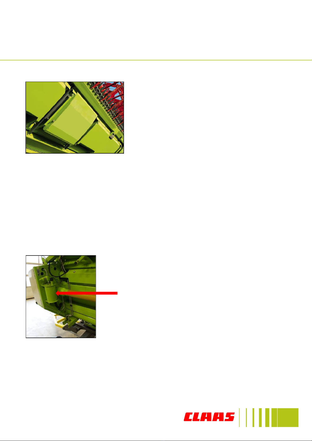
Table auger
The table auger is important for the
transportation of material to the
front elevator.
The timing of the retractable fingers
can be adjusted for different crops by
opening up the guard on the RHS for
V750 & V900 and both sides for
V1050 & V1200 cutterbars and
adjusting the lever with a spanner.
Use the top holes for short crops and
the lower holes for tall crops. The 3rd
hole from bottom is the standard
setting.
1. Adjust the stripper plates behind the auger.
2. Remove the intermediate retractable fingers along the length of the auger
leaving just the middle ones.
3. Alter the height of the auger within the trough of the cutterbar. There should
be a minimum gap of 20mm between the trough and the auger flights.
4. Alter the speed of the auger by swapping the sprocket on the LHS of the
cutterbar (V750 & V900) or changing the optional gears inside the auger drive
gearbox (V1050 & V1200).
Crop Wrapping
If a problem occurs with crop wrapping around the table auger in difficult conditions
there are a number of procedures that can be carried out, try one thing at a time.
V1050 & 1200
Cutterbar
Adjustments
5
Skids
The skids underneath the cutterbar should be set
to suit the local conditions i.e stones, loose soil
etc. It is recommended that they are lifted right
up in abrasive conditions.
VARIO
VARIO cutterbars allow the operator to vary the position of the knife to suit different
crop conditions. In short crops the knife can be retracted by up to 10cm and
extended by 20cm from its ‘normal’ position for taller crops. For extremely tall crops
such as Oilseed Rape the knife can be extended by 50cm from it’s normal position, in
conjunction with filler plates. (V1050 & V1200 require a auger drive shaft extension)
When using the cutterbar in normal conditions up to 4 knife positions can be
saved as part of the pre-set working positions, providing the function is
activated in CEBIS.
Check the hydraulic oil level in the oil tank on the
back of the cutterbar daily.
Cutterbar
Adjustments
6
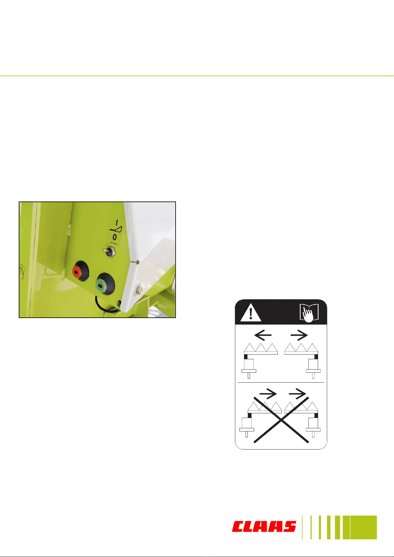
When the filler plates are being used, ensure
that the knife is retracted against the filler
plates on a daily basis and make sure the
power switch for the cutterbar is SWITCHED
OFF.
TURN OFF ‘VARIO AUTOMATICS’ IN CEBIS WHEN USING FILLER PLATES.
When setting the knives after
fitting the filler plates. The
knives must be in the
outermost position.
Cutterbar
Adjustments
When fitting the filler plate kit. (1)retract Knife/table (2) unlatch pins on both sides.
(3)Remove the drive shafts from gearbox. (4) Push Knife/Table out to its maximum.
(5) Fit side fillers. (6) fit filler plates, starting with the middle working out and
making sure the outside plate seal is up. (7) when plates are located correctly,
retract the knife making sure the plates are locked in and turn off switch. (8) Latch
in pins on both sides. (9) fit side knife and hydraulic connections. (10) Fit the drive
extensions and time up knives. To remove filler plates carryout operation in
reverse.

7
Notes

8
Notes

CLAAS U.K. Ltd
Saxham
Bury St. Edmunds Suffolk
IP28 6QZ
Tel: 01284 763100
Fax: 01284 769839
www.claas.co.uk
This manual suits for next models
3
Other Claas Tractor Accessories manuals


