Spearhead TWIGA CLASSIC S51 User manual
TWIGA CLASSIC
0
TWIGA CLASSIC
S51/S55/S60/T65
December 2020
8999133

TWIGA CLASSIC
1
IMPORTANT
VERIFICATION OF WARRANTY REGISTRATION
DEALER WARRANTY INFORMATION & REGISTRATION
VERIFICATION
It is imperative that the selling dealer registers this machine with Spearhead
Machinery Limited before delivery to the end user –failure to do so may affect the
validity of the machine warranty.
To register machines go to the Spearhead Machinery Limited web site at
www.spearheadmachinery.com, log onto ‘Dealer Inside’ and select the
‘Machine Registration button’which can be found in the Service Section of the
site. Confirm to the customer that the machine has been registered in the section
below.
Should you experience any problems registering a machine in this manner please
contact the Spearhead Service Department on 01789 491867.
Registration Verification
Dealer Name:
……………………..…………………………………………………………….
Dealer Address:
…….………………………………………………………………………….
Customer Name:
……………………..…………………………………………………………
Date of Warranty Registration:
……/……/...…… Dealer Signature: ………………..……
NOTE TO CUSTOMER / OWNER
Please ensure that the above section has been completed and signed by the
selling dealer to verify that your machine has been registered with Spearhead
Machinery Limited.
IMPORTANT: During the initial ‘bedding in’ period of a new machine it is the
customer’s responsibility to regularly inspect all nuts, bolts and hose
connections for tightness and re-tighten if required. New hydraulic
connections occasionally weep small amounts of oil as the seals and joints
settle in –where this occurs it can be cured by re-tightening the connection
–refer to torque settings chart below. The tasks stated above should be
performed on an hourly basis during the first day of work and at least daily
thereafter as part of the machines general maintenance procedure.

TWIGA CLASSIC
2
CAUTION: DO NOT OVER TORQUE HYDRAULIC FITTINGS AND
HOSES
TORQUE SETTINGS FOR HYDRAULIC FITTINGS
HYDRAULIC HOSE ENDS
PORT ADAPTORS WITH BONDED SEALS
BSP
Setting
Metric
BSP
Setting
Metric
1/4”
18 Nm
19 mm
1/4”
34 Nm
19 mm
3/8”
31 Nm
22 mm
3/8”
47 Nm
22 mm
1/2”
49 Nm
27 mm
1/2”
102 Nm
27 mm
5/8”
60 Nm
30 mm
5/8”
122 Nm
30 mm
3/4”
80 Nm
32 mm
3/4”
149 Nm
32 mm
1”
125 Nm
41 mm
1”
203 Nm
41 mm
1.1/4”
190 Nm
50 mm
1.1/4”
305 Nm
50 mm
1.1/2”
250 Nm
55 mm
1.1/2”
305 Nm
55 mm
2”
420 Nm
70 mm
2”
400 Nm
70 mm

TWIGA CLASSIC
3
Contents
General Information
Introduction 5
Specification 6
Safety
Safety Recommendation 7
Overhead Power Lines 9
Safety Decal 11
Warning Signs 11
Road Work Guidelines 11
Training 12
Tractor Requirements 12
Lighting Kits 12
Lifting Points 12
Installing your Machine
Attaching your Machine to the Tractor –Using 3 Point Linkage 13
Attaching your Machine to the Tractor - Using Axle Mounting 17
Running up your Machine 19
Removing from the Tractor 20
Hydraulic Proportional Controls - 2SV 21
Cable Controls 22
PILOT Controls 23
Operation Warnings 24
Moving into Transport Position 25
Operation 27
Options
Oil Cooler 29
Head Float 30
Arm Float 31
Debris Blower 32
Hydraulic Rear Roller 33
Autopilot 34
Quad Saw 39
Cutter Bar 42
Telescopic Arm 43
Forward Reach 44

TWIGA CLASSIC
4
Service & Maintenance
Daily Grease Points 45
Torque Settings 46
Hydraulic Hoses 47
Oil Supply 48
Filtration Maintenance 48
Pin & Bushes 49
Storage 49
Regular Service Chart 50
Diagnostics
Pump & Motor Failure Prevention 50
Trouble Shooting 51

TWIGA CLASSIC
5
Introduction
The TWIGA is a very robust high capacity reach mower that is easy to operate
and maintain. To ensure trouble-free operation this manual should be carefully
studied.
The term Left and Right hand applies to the machine when coupled to the
tractor and viewed from the rear, this also applies to the tractor.
Important Note
The information contained in this manual is correct at the time of publication.
However, in the course of constant development, changes in specification are
inevitable. Should you find the information given in this book different to the
Machine it relates to please contact the “After Sales Department” for advice.
Please ensure that this manual is handed to the operator before using the
machine for the first time. The operator must fully understand the contents
of this manual before using this machine.
(If the machine is resold the Manual must be given to the new owner.)
TWIGA CLASSIC
6
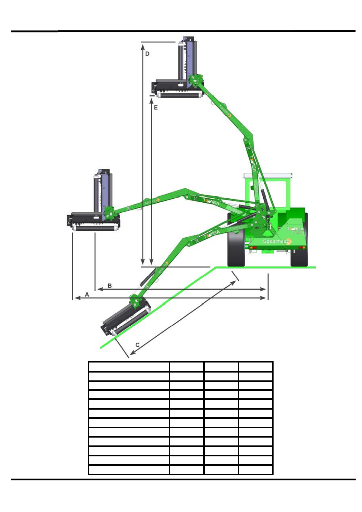
Specification
S55
S60
T65
Weight inc. Oil (Kg)
1360
1380
1540
Weight of head (Kg)
300
300
300
Tractor horse power
85-120
95-120
100-140
Min. tractor weight (Kg)
3500
3750
4000
Oil tank capacity (ltr)
230
230
230
Reach A (m)
5.4
5.9
6.4
Reach B (m)
4.9
5.3
5.9
Reach C (m)
3.9
4.2
4.7
Reach D (m)
6.5
6.7
7.2
Reach E (m)
4.9
5.2
5.7

TWIGA CLASSIC
7
Safety Recommendations
Beware of the following Potential Dangers associated with the use of this
machine:
•Becoming trapped when hitching or unhitching
•Tractor overbalancing when arm is extended
•Electrocution due to hitting overhead power lines
•Getting caught on rotating power take off (PTO)
•Being hit or caught by any moving part, e.g. belts, pulleys, arms, cutting
head
•Being hit by flying debris or machine parts due to machine damage
•Machine overbalancing when not in use
•Injection of high pressure oil from damaged couplings or hydraulic
hoses
•Accidents due to collision with other machines, or debris left on road
Always
•Ensure the operator has read this handbook and has been trained to
use the machine.
•Ensure all cab safety guards are in place and all tractor windows
closed.
•Before leaving the tractor cab always ensure that the flail head is firmly
on the ground, no weight is on the machine’s hydraulics and the rotor
has stopped spinning.
•Check that all guards are properly fitted and there are no damaged or
loose parts. Particular attention should be given to the flails to ensure
they are not damaged, cracked or missing.
•Inspect work area for wire, steel posts, large stones and other
dangerous materials and remove before starting work.
•Beware of the danger of overhead power cables. The operator must
be aware of the maximum height and reach of the machine when
working under power cables. For more information contact the Health
and Safety Executive or your local power company.
•Ensure that all warning labels are always visible and that they are not
damaged, defaced or missing.
•Lower the head to the ground when parking up
•Fit locking pins to slew and height before transport and before
unhitching when applicable.
•Wear ear defenders if operating without a quiet cab or with the cab
windows open.
•Ensure tractor guards are fitted correctly and are undamaged
•Work at a safe speed, taking into account terrain, passing vehicles and
obstacles
•Ensure that the tractor meets the minimum weight recommendations of
the machine manufacturer and that ballast is used if necessary
•Check that machine fittings and couplings are in good condition

TWIGA CLASSIC
8
•Follow the manufacturer’s instructions for attachment and removal of
machine from the tractor are warning signs to alert others to the type of
machine working in the vicinity. Signs should be placed at both ends of
the work site and should be in accordance with Department of
Transport recommendations.
•Ensure flails are of the type recommended by the manufacturer, are
securely fitted and are undamaged.
•Ensure hydraulic pipes are correctly routed to avoid damage from
chafing, stretching, pinching or kinking.
•Disengage the machine, stop the engine and remove the key before
leaving the tractor cab for any reason.
•Clean up any debris left at the work site.
•Ensure that when you remove the machine from the tractor it is
secured in a safe position using the stands provided.
Never
•Never operate the machine with other people present, as it is possible
for debris, including stones, to be discharged from the front and rear of
the flail head.
•Never operate the machine until you have read and understood the
relevant Handbook and are familiar with the controls.
•Never use a machine that is poorly maintained or has guards that are
damaged or missing
•Never allow an inexperienced person to operate the machine without
supervision.
•Never use or fit a machine onto a tractor if it doesn’t meet the
manufacturer’s specification.
•Never use a machine if the hydraulic system shows signs of damage.
•Never attempt to detect a hydraulic leak with your hand, use a piece of
card.
•Never allow children to play on or around the machine at any time.
•Never attempt any maintenance or adjustment without first disengaging
the PTO, lowering the head to the ground, stopping the tractor engine
and applying the tractor parking brake.
•Never leave the cab without removing the ignition key.
•Never operate the tractor or any controls from any position other than
from the driving seat.
•Never stop the engine with the PTO engaged.
•Never operate with flails missing.
•Never operate PTO above recommended speed for your machine, 540
R.P.M. flail head, 150 R.P.M. cutter-bar.
•Never operate with wire around the rotor. Stop immediately.
•Never use the head at an angle, which may throw debris towards the
cab.
•Never attempt to use the machine for any purpose other than that it
was designed for.
•Never transport with the PTO engaged
•Never enter the working area of the machine (risk of injury!)
•Never transport with the controls live, always turn off electrical isolator
switch (red) and disconnect supply.

TWIGA CLASSIC
9
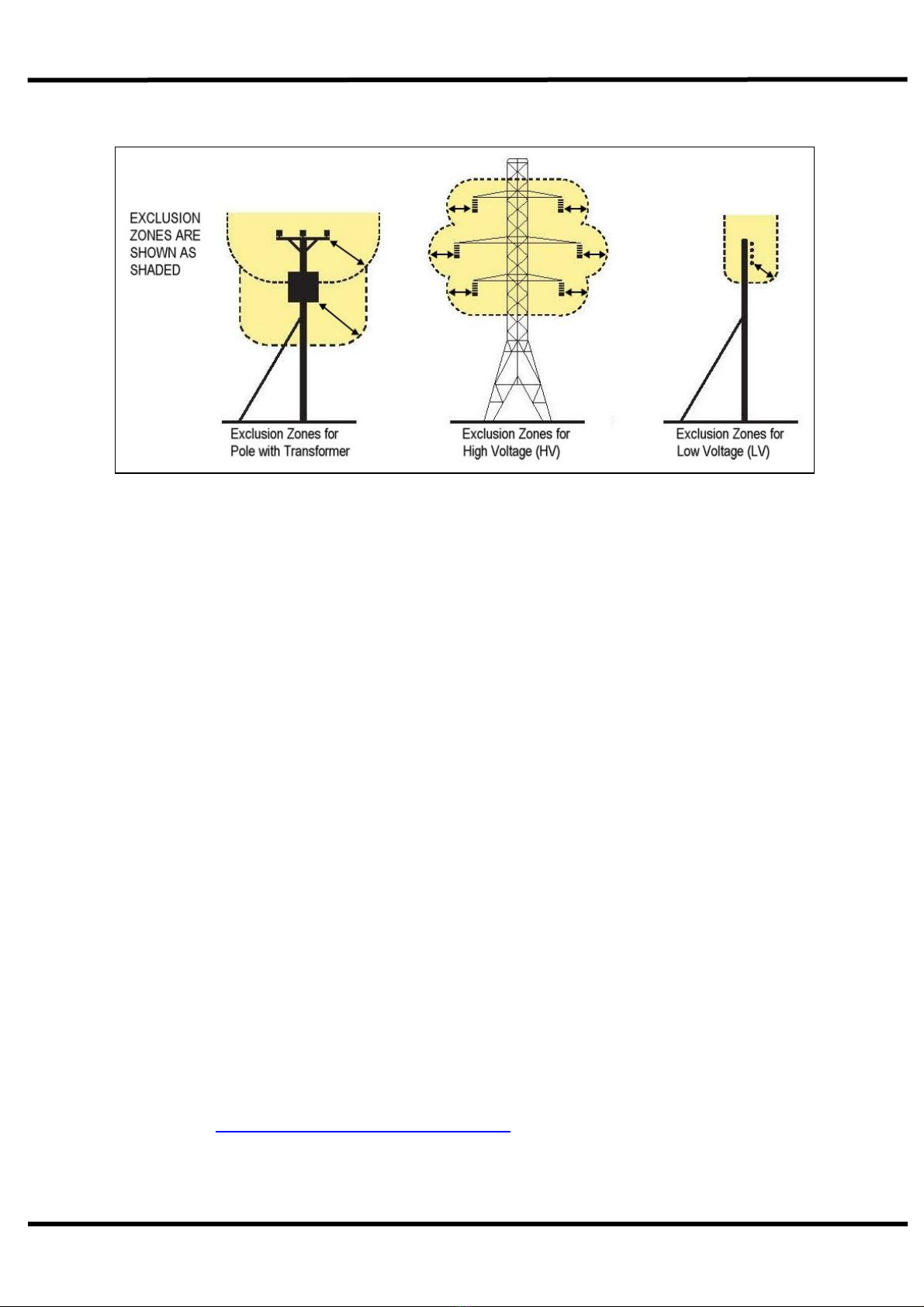
Overhead Power Lines
It cannot be stressed enough the dangers involved when working in the vicinity of
Overhead Power Lines (OHPLs). Some of our machines are capable of reach in
excess of 8 metres (26’); they have the potential to well exceed, by possibly 3 metres
(9’ 9”), the lowest legal minimum height of 5.2 metres from the ground for 11,000 and
33,000-volt power lines.
Remember electrocution can occur without actually coming into contact with a power
line as electricity can ‘flashover’ when machinery gets close to it.
WARNING: All operators must read the following information and be
aware of the risks and dangers involved when working in the vicinity
of Overhead Power Lines (OHPLs).
Wherever possible the safest option is always to avoid working in areas close to
OHPLs.
Where unavoidable, all operators must perform a risk assessment and implement a
safe procedure and system of work –see following page for details.
All operators should perform a risk assessment before operating the machine within
10m horizontal distance of any OHPLs.
Minimum Heights for Overhead Power Lines
Absolute Minimum Exclusion Zones for Specific Overhead Power Lines
TWIGA CLASSIC
10
Definitions of Exclusion Zones
Risk Assessment
Before starting to work near OHPLs you should always assess the risks. The
following points should be observed;
Know the risks of contacting OHPLs and the risk of flashover.
Find out the maximum height and maximum vertical reach of your machine.
Find out the location and route of all Power Lines within the work area.
Find out the operating voltage of all Power Lines within the work area.
Contact the local Distribution Network Operator (DNO) who will be able to advise
you on the operating voltage, safe minimum clearance distance for working and
additional precautions required.
Never attempt operate the machine in an exclusion zones.
Always work with extreme caution and plan your work ahead to avoid high risk
areas.
If doubt exists do not work in the area –never risk the safety of yourself or others.
Emergency Action for Accidents Involving Electricity
•Never touch an overhead line - even if it has been brought down by machinery, or
has fallen. Never assume lines are dead.
•When a machine is in contact with an overhead line, electrocution is possible if
anyone touches both the machine and the ground. Stay in the machine and lower
any raised parts in contact or drive the machine out of the lines if you can.
•If you need to get out to summon help or because of fire, jump out as far as you
can without touching any wires or the machine - keep upright and away.
•Get the electricity company to disconnect the supply. Even if the line appears
dead, do not touch it - automatic switching may reconnect the power.
Further information and leaflets on this and other agricultural safety subjects
are available on the ‘Health & Safety Executive’ website at the following
address: www.hse.gov.uk/pubns/agindex.htm

TWIGA CLASSIC
11
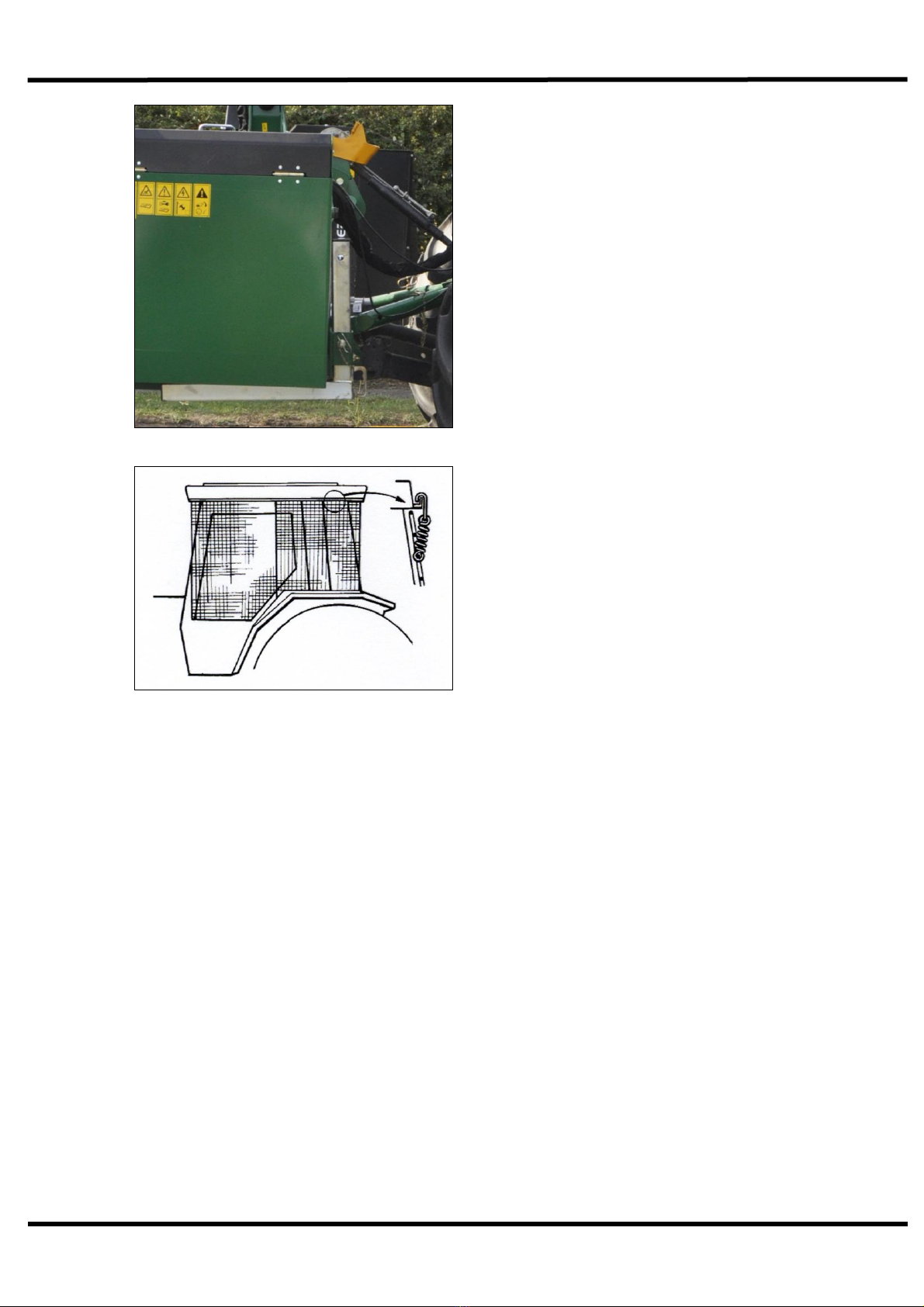
Safety Decal
Warning Signs
You are advised to display clear warning signs to indicate the type of machine
when working in public places. The signs should be carefully placed at either
end of the work site to give advanced warning of the hazard.
Contact your local Highways Authority or Department of Transport for more
information.
Roadwork Guidelines:
•On two-way roads, one set of signs should face the traffic in each
direction.
•Work should be within 1 mile of the signs.
•Work only when visibility is good and at times of low risk, e.g. NOT
during rush hour.
•Vehicles should show an amber flashing light.
•Vehicles should be conspicuously coloured.
•Debris should be removed from the road or path at regular intervals
and the operator should wear high visibility clothing.
•Collect all warning signs promptly when the job is finished.
Warning
Check all bolts are tight
every 8 hours.
Warning
Shut off engine and remove
key before performing
maintenance or repair work.
Warning
Beware of
escaping fluid.
Warning
Beware of overhead
electrical power lines.

TWIGA CLASSIC
12
Training
It is the responsibility of the Spearhead dealer to provide instruction on the
safe installation, operation and maintenance of the machine in the first
instance. Further training is available from Spearhead Machinery Ltd on
request, at cost.
Tractor Requirements
•Check your Tractor size and minimum weight on the Specification table
•Before hitching, ensure position control is selected. Do not attempt to
hitch in draft control.
•Set wheel width as wide as possible.
•Ballast weight is to be fitted within tractor manufacturer’s recommended
requirements
•Check chains and stabilisers must be in good working order to hold the
machine firmly. Do not operate without checking chains and stabilisers
are tight.
•Spearhead particularly recommend ‘turn buckle’ type stabiliser.
•Set linkage lift rods to an equal length
•Certain machines require a 12V fused electric supply that is controlled
by the tractor’s ignition key.
•Spearhead particularly recommend three-point linkage of ball end type,
we do not advise the use of claw type hitching. The quick release
latches should be checked, if worn or insecure they may cause
accidental damage or personal injury if the machine becomes
detached.
•Ensure tractor link arms can be isolated from accidental lifting.
Lighting Kits
For additional safety, rear mounted lighting kits are already fitted as standard.
For more detailed information, contact the Department of Transport or your
local Highways Authority.
Pallet Fork Lifting Points

TWIGA CLASSIC
13
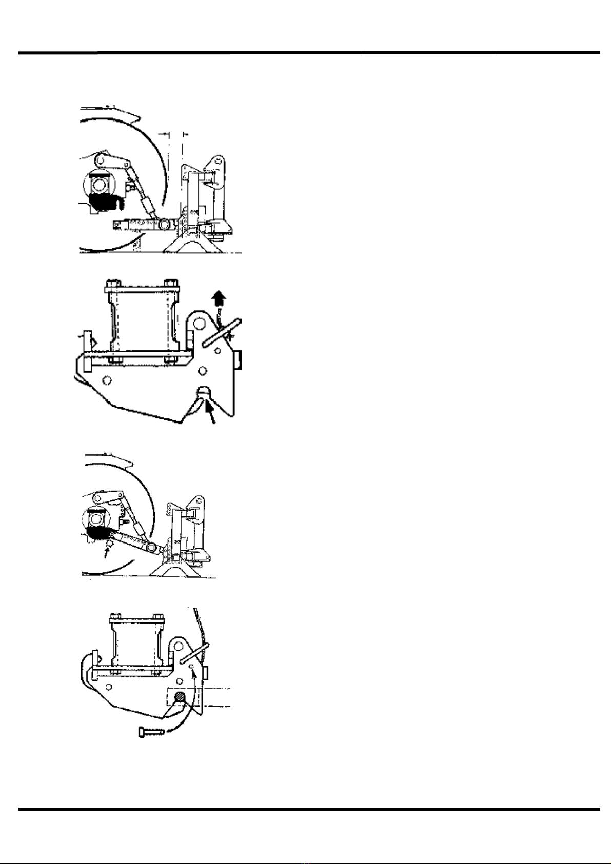
Attaching Machine to Tractor –3 Point Linkage
1. Reverse tractor to machine and
attach lower links.
2. Fit stabiliser bracket into top link
clevis and fit top link. The standard
link comes with a Cat III hole plus a
Cat III to Cat II reducing bush, a
28mm bracket is available on request.
3. Fit stabiliser tubes between A frame
and stabiliser bracket. Ensure the
tubes are free to slide, do fit locking
pins.

TWIGA CLASSIC
14
4. Raise machine to required height.
Both P.T.O. shafts should be roughly
in-line, an upward angle of up to 17° is
acceptable to ensure adequate
clearance.
5. Adjust the top link so that the
machine sits vertically.
6. Fit locking pins to stabiliser tubes,
then the linkage can be lowered so
that the weight of the machine is taken
by the stabilisers. It is essential that
both tubes are set to equal lengths,
more than one attempt may be
required to achieve the correct height
as the machine settles on the
stabilisers.
TWIGA CLASSIC
15
7. It is recommended that the controls
are mounted in-place of the seat
armrest on the side of the cutting
head. A pivoting bracket is supplied
with every machine, if additional
brackets are required contact your
local dealer. A 12v/30Amp power
supply will be required.
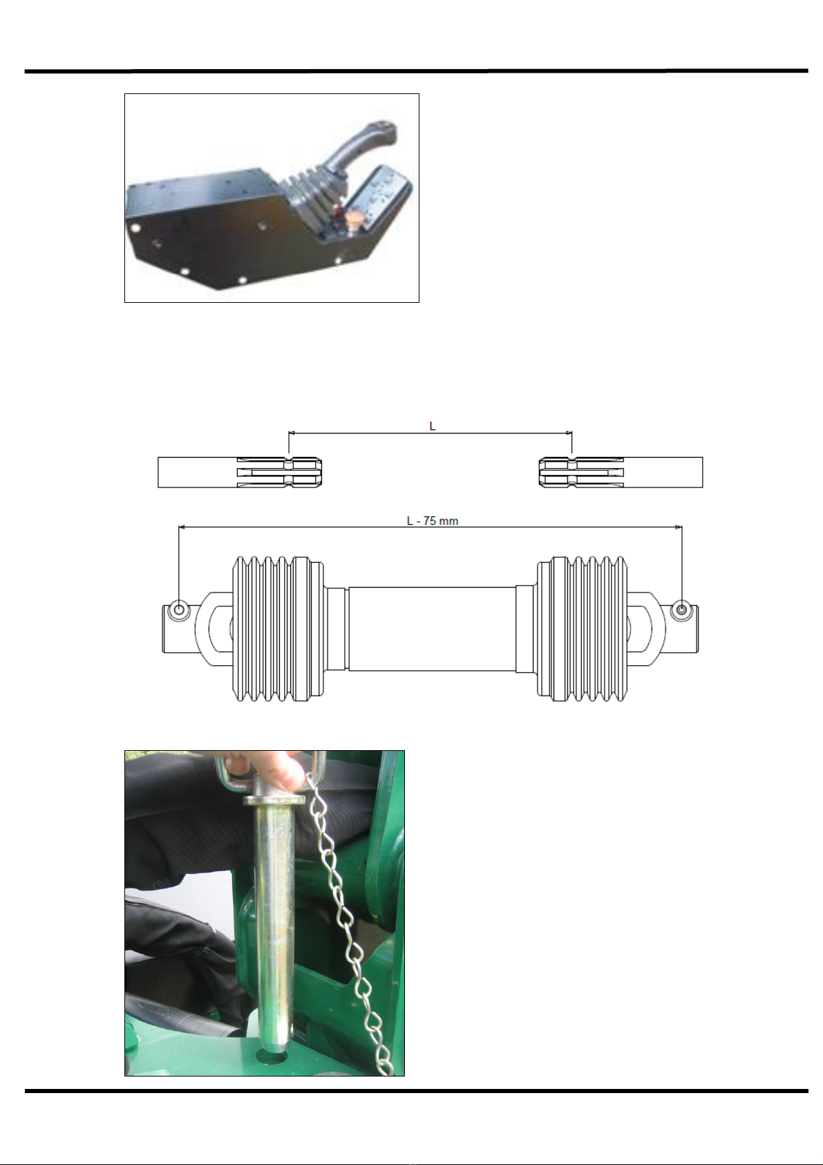
8. Ensure the engine is switched off and then fit the P.T.O. shaft. If fitting for
the first time, follow instructions below to cut P.T.O. to length. Ensure both
sections are cut to equal lengths
9. Remove slew locking pin.
TWIGA CLASSIC
16
9. Raise leg stands to ensure they
don't get damaged. Adjust check
chains ensure the machine is
secure and cannot swing from
side to side.
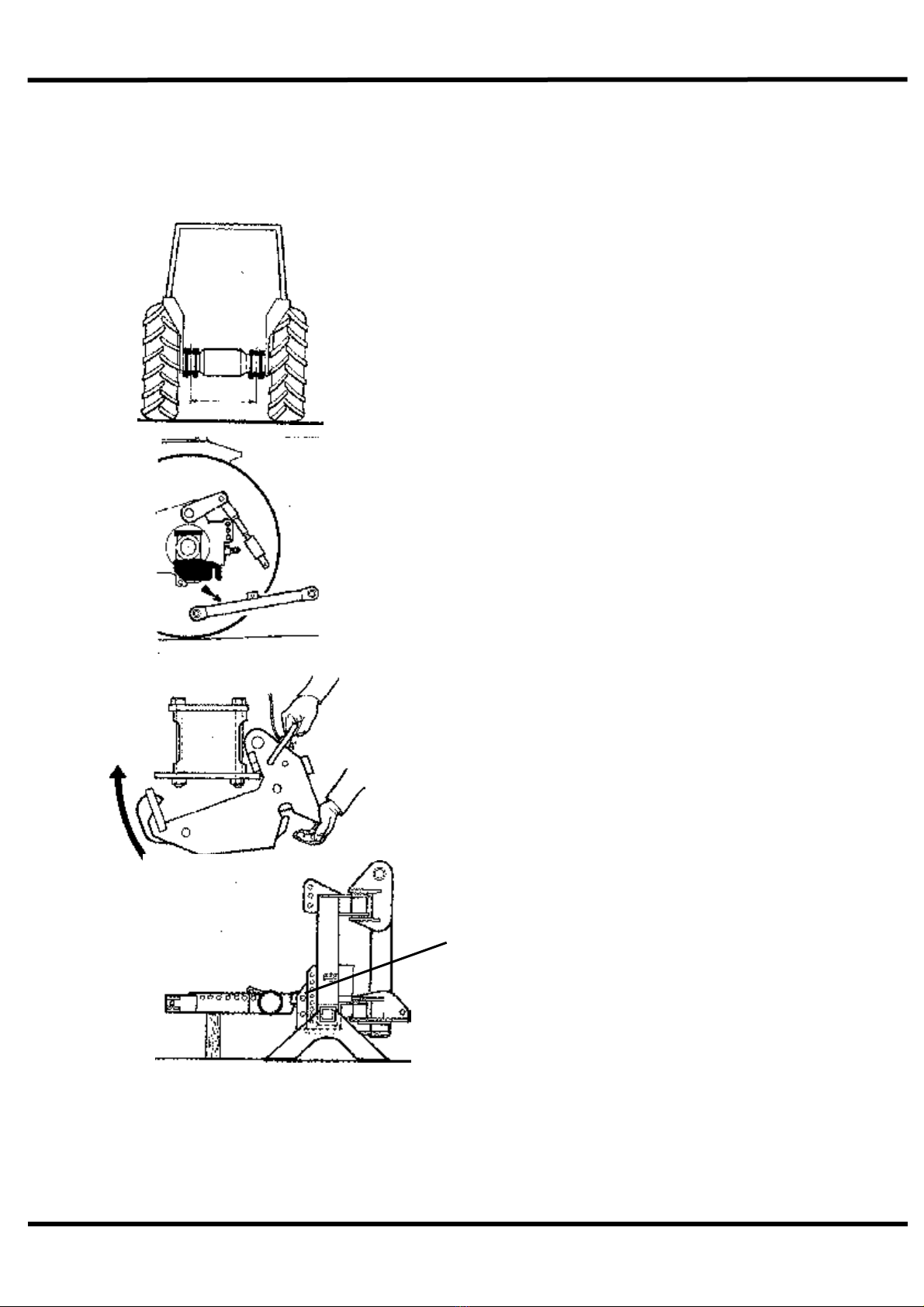
10. Use only tractors with safety glass.
If windows are not laminated safety
glass, polycarbonate glazing must be
fitted between operator and cab
meshing. Shape mesh to cover all
windows that the driver will look
through to view flail head in any
operating position. Mesh can be
retained by springs and clips supplied,
but it is the operator’s responsibility to
ensure guarding is firmly in place.
Warning
Avoid raising the tractor linkage once the stabiliser bars are locked in place.
Always lower the tractor linkage and allow all the weight to be carried by the
stabiliser frame. Failure to observe this warning will result in bending the stabiliser
bracket. When operating the machine’s controls do so only when seated in the
tractor cab. Do not allow anyone to stand on or amongst linkage for any reason
TWIGA CLASSIC
17
Attaching Machine to Tractor –Axle Mounting
1. Mount axle brackets as instructed
on separate fitting sheet specific to
your tractor type.
2. Detach tractor draft links.
4. Assemble sub frame to suit axle width
1m or 1.1m, mount sub frame assembly
to your machine using bottom pin holes.
3. Fit lift-in hitch assembly
TWIGA CLASSIC
18
Please Note
6. Open catch
5. Offer up frame to tractor and adjust to
give required length. Distance “X” to be
kept to the minimum ensuring the machine
is close coupled, as a guide set the same
as original. Attach tractor lift links to frame
with suitable pins.
Note: The hole sizes may not match the
tractor links, this will not matter as the
machines weight will be carried on the
stabilisers.
7. Ensure top link is fitted to prevent
machine from tipping over before raising. Lift
sub frame until it engages in the catches.
Note: It is best to mount the sub frame to the
tractor first.
8. Insert latch locking pin

TWIGA CLASSIC
19
Running Up Your Machine
1. First ensure the rotor is in the ‘off’ position and P.T.O. drive is
disengaged, and then start the tractor.
2. Engage P.T.O. into gear and run machine up to half revs allowing oil to
circulate for about 5 minutes before operating arms.
3. Re-check oil level, - check for oil leaks
4. Operate the arms through the full amount of travel, check all
movements are functioning correctly.
5. Place flail head near ground in a safe position and with tractor revs low
idle, select ‘start’ position for the flail motor.
6. Once rotor is settled, slowly increase revs of P.T.O. to 540 R.P.M. and
run for a further 5 minutes. Slowly reduce revs and then disengage
P.T.O.
7. Check all hoses for kinks, pinching, chafing and leaks.
8. Re-check oil level.
Warning
The rotor will take a long time to stop. Never leave the cab until P.T.O. is
disengaged, engine stopped, and rotor has stopped spinning.
This manual suits for next models
3
Table of contents
Other Spearhead Tractor Accessories manuals


