clare ClareVision User manual

Page 1 | 53
Network Video Recorder
(NVR) User Manual
Doc ID: 2021-05-2107-02

Page 2 | 53
Safety Instructions
This manual is intended to ensure that user can use the product properly without danger or any property loss.
Please read it carefully and do not discard for future reference. Precaution measures are divided into
“WARNINGS” and “CAUTIONS” as below:
WARNING: Neglecting any of the warnings may cause serious injury.
CAUTIONS: Neglecting any of the CAUTIONS may cause injury or equipment damage.
WARNING
•Use recommended cord sets (power cords) with the correct specifications.
CAUTIONS
•Do not place or install equipment directly in sunlight or near heating devices.
•Keep equipment installed correctly and fully.
•Install the equipment in a well-ventilated place, do not block vents.
•Only use equipment within rated input/output.
•Transport, use, and reserve the equipment within the proper humidity range (10 to 90%) and
temperature range (14 to 131°F, -10 to 55℃).
•When cleaning the device, unplug the power cord and completely shut off the power.
•Do not use volatile solvents such as alcohol, benzene, or thinner when cleaning the device. Do not use
strong or abrasive cleaning agents. This can damage the surface coating.
•Purchase the NVR dedicated hard drive recommended by the equipment manufacturer from the correct
channels to ensure the quality and usage requirements of the hard drive.
•Make sure that the alarm cable is firmly installed with a solid contact.
•Make sure that the NVR is properly grounded.
NOTE: After receiving the product, verify the contents of the package according to the packing list in the box.

Page 3 | 53
Contents
Chapter 1: Product Introduction................................................................................................................... 6
1.1 Product Manual .................................................................................................................................. 6
1.2 Defaults ............................................................................................................................................... 6
1.3 Product Features................................................................................................................................. 6
1.4 Function Features ............................................................................................................................... 6
Local monitoring ................................................................................................................................... 7
Hard disk management......................................................................................................................... 7
Video Record and Playback................................................................................................................... 7
User Management ................................................................................................................................ 7
Data backup .......................................................................................................................................... 7
Alarm and exception management....................................................................................................... 8
Other Local Functions ........................................................................................................................... 8
Network Function ................................................................................................................................. 8
Chapter 2: NVR Appearance ......................................................................................................................... 9
2.1 Front Panel.......................................................................................................................................... 9
2.2 Rear Panel ........................................................................................................................................... 9
2.3 Mouse Input...................................................................................................................................... 10
2.3 Mouse Input...................................................................................................................................... 10
Chapter 3: Connecting NVR ........................................................................................................................ 11
3.1. Hard Disk Installation .......................................................................................................................11
3.1.1 Hard disk installation ................................................................................................................. 11
3.1.2 Device Connection .....................................................................................................................11
Chapter 4: NVR Setup (WEB) ...................................................................................................................... 13
4.1 Internet connection .......................................................................................................................... 13
4.2 Browser Login ...................................................................................................................................14
4.2.1 Change password.......................................................................................................................14
4.2.3 Forgot password ........................................................................................................................15
4.2.4 Exiting Web Console ..................................................................................................................17
3.3 Install the necessary browser plugins............................................................................................... 17
4.4 Preview.............................................................................................................................................. 19
Chapter 5: Configuration ............................................................................................................................ 22

Page 4 | 53
5.1 Configuration ....................................................................................................................................22
5.1.1 Local Configuration .................................................................................................................... 22
5.2 Channel ............................................................................................................................................. 22
5.2.1 Camera ....................................................................................................................................... 22
5.2.2 PoE Power Configuration ...........................................................................................................22
5.2.3 PoE Bonding Configuration ........................................................................................................23
5.3 OSD....................................................................................................................................................23
5.4 Image.................................................................................................................................................24
5.4 Privacy Mask .....................................................................................................................................27
5.6 Channel Name...................................................................................................................................28
Chapter 6: Storage ...................................................................................................................................... 29
6.1 Record ............................................................................................................................................... 29
6.1.1 Record ........................................................................................................................................ 29
6.1.2 Encode........................................................................................................................................30
6.2 Storage Device .................................................................................................................................. 30
6.2.1 HDD ............................................................................................................................................30
6.2.2 Cloud Storage............................................................................................................................. 31
Chapter 7: System....................................................................................................................................... 32
7.1 General.............................................................................................................................................. 32
7.1.1 Device Settings...........................................................................................................................32
7.1.2 Date............................................................................................................................................32
7.1.3 DST .............................................................................................................................................33
7.2 Network ............................................................................................................................................ 34
7.2.1 TCP/IP.........................................................................................................................................34
7.2.2 DDNS ..........................................................................................................................................34
7.2.3 E-Mail ......................................................................................................................................... 35
7.2.4 P2P .............................................................................................................................................35
7.2.5 FTP.............................................................................................................................................. 36
7.2.6 UPNP ..........................................................................................................................................36
7.2.7 PPPOE.........................................................................................................................................37
7.2.8 Address Filter .............................................................................................................................37
7.3 User................................................................................................................................................... 37

Page 5 | 53
7.4 Local Alarm........................................................................................................................................ 38
7.4.1 Alarm Input ................................................................................................................................38
7.4.1 Alarm Output .............................................................................................................................39
7.5 Normal Event .................................................................................................................................... 39
7.5.1 Motion Detection.......................................................................................................................39
7.5.2 Exception.................................................................................................................................... 41
7.5.3 Video Loss ..................................................................................................................................42
7.5.4 Buzzer.........................................................................................................................................43
7.5 Smart Event.......................................................................................................................................44
7.5.1 Human Body Detection.............................................................................................................. 44
7.5.2 Line Crossing ..............................................................................................................................44
7.5.3 Regional Intrusion ...................................................................................................................... 45
7.5.4 Loitering .....................................................................................................................................46
7.5.5 People Gathering .......................................................................................................................47
Chapter 8: Maintenance .............................................................................................................................48
8.1 Device................................................................................................................................................ 48
8.2 Log.....................................................................................................................................................49
8.3 Manual Upgrade ............................................................................................................................... 49
8.3 Schedule Reboot ...............................................................................................................................50
8.3 Default............................................................................................................................................... 50
Chapter 9: Video Playback .......................................................................................................................... 51
Chapter 9: Picture ....................................................................................................................................... 52
Chapter 10: NVR maintenance and best practices .....................................................................................53

Page 6 | 53
Chapter 1: Product Introduction
1.1 Product Manual
ClareVision NVRs provide local video streaming preview, multi-screen split display streaming, local real-time
storage of video files, support for mouse shortcuts, and remote management and control.
This manual will guide you through all NVR settings, options, and provide additional information on NVR operation.
1.2 Defaults
The factory default username is “admin” and password being the first six characters of the UUID.
NVR and PoE NVR factory default is set to DHCP.
1.3 Product Features
This section introduces the camera product features:
•The "device" mentioned in this manual mainly refers to the NVR.
•The "IP device" mentioned in this manual mainly refers to the IP Camera.
•The "channel" mentioned in this manual refers to the NVR's IP channel.
•Click the "X" or "Cancel" button to return to the previous screen.
•Click All Interfaces Default to restore the current factory default settings.
•Click "Apply", "Confirm", and "Save" on all screens to save the current settings.
•Click "Copy" on all interfaces to enter the copy channel interface. Select the channel in which to copy the
current channel.
1.4 Function Features
•H.264 videos condense format, support 4K/6M/5M/4M/3M/2M/1080P/720P/D1 resolution network
camera input.
•G.711U, G711a, ADPCM_DVI4, AAC audio condense format.
•Each channel supports three-stream encoding, including an MJPEG stream.
•Windows-style user interface embedded real-time Linux3.0 operating system.
•Support for independent adjustment of coding parameters for each channel, including coding type,
resolution, frame rate, and bitrate.
•Manual capture and image playback.
•Preview, recording, playback, and backup.
•Select NVRs support fisheye correction, dual-screen preview, PoE, humanoid detection, crossover
detection, regional intrusion, people gather detection, and people gathering.
•Only one USB interface: The NVR needs to use USB interface for task such as Configuration import,
Configuration export, backup, camera update, and manual update. You must first select the
corresponding function, such as click "Config import", and then you receive a pop-up "Please insert the
USB disk". Follow the prompt within the 60 second countdown, and then unplug the mouse and plug it
into the USB device before the countdown ends. After the NVR recognizes the USB device, it automatically
proceeds to the next step.

Page 7 | 53
Local monitoring
•Supports local VGA and HDMI output, with HD supporting up to 4K resolution output.
•Screen previews:
o4-channel NVRs support 1/4
o8-channel NVRs support 1/4/8
o16-channel NVRs support 1/4/8/9/16
o32-channel NVRs support 1/4/8/9/ 6/25/32
•Adjustable preview channel position (drag them to the desired position using the mouse).
•Set manual or auto-tour preview with an automatic polling cycle.
•Supports video motion detection, video loss detection, and intelligent detection.
•Achieve IP PTZ camera control through the ONVIF protocol.
Hard disk management
•Each SATA interface supports up to an 8T hard drive.
•Hard disk formatting.
•Hard disk loss and hard disk abnormal alarm.
Video Record and Playback
•Video compression standard is H.264/H.264+/H.265/H.265+, with timed recording function.
•Supports recording schedules using drawing and editing methods.
•Supports simultaneous main and sub-stream recording.
•Supports cyclic writing.
•A maximum of 6 recording times can be set each day. The recording trigger mode can be set
independently for different time periods.
•Recording trigger modes include Normal, Motion, Alarm, M&A, Smart Events.
•Supports video data retrieval and playback by channel, video type, and date.
•Multiple playback modes (adjustable with mouse): Play/Pause, Reverse, Stop, Single Back, Single Forward,
Speed Down, and Speed Up.
•Select the screen area for local zoom.
•Supports multi-channel simultaneous playback of video.
User Management
•Three-level user management: Administrators can create multiple operation users and set their privileges.
Data backup
•Support for backup via USB2.0 or USB3.0 interface.
•Support for U disk or mobile hard disk in FAT32, NTFS, exFAT and other formats.
•Support for batch backup by file and time.
•Support for iVMS320 clip-by-clip backups.
•Support for webpage clip and download video files by time.

Page 8 | 53
Alarm and exception management
•Select models support multi-channel external alarm input and output.
•Support for video loss alarm, motion alarm, network disconnection alarm, IP conflict alarm, hard disk
error, and no disk alarm.
•Support our smart IPC face detection, Crossover, Regional intrusion, people stay, people gathering, and
other intelligent detection access and linkage.
•Various alarms can be set to trigger the buzzing alarm, sending mail and screen display.
•Various alarms can be set to trigger pop-up alarm prompts, voice warnings, and send emails notifying
users.
Other Local Functions
•Users can quickly and easily set the system parameters using the NVR buttons and USB mouse.
•Complete operations: alarms, exceptions, information logging and retrieval.
•Select models support local alarms and upgrades for front-end features.
•Supports gesture password function.
Network Function
•3536D series devices support a 10M/100M adaptive network interface and the 3536/3536C series devices
support 10M/100M/1000M adaptive network interface.
•Support for remote client privileged access helps improve system security.
•Supported protocols: TCP/IP protocol cluster, DHCP, DNS, HTP, SMTP, RTSP, UPnP, HTTPS and other
protocols.
•Embedded WEB SERVER and support for ONVIF protocol access to platform.
•Remote access to playback, download, parameter configuration, FTP server configuration, running status,
systems log, alarm status, manual trigger & stop recording, manual trigger & stop alarm output, alarm
pushes, PTZ control, remote formatting of hard disk, upgrading the program, restart, and other operations
for system maintenance.

Page 9 | 53
Chapter 2: NVR Appearance
2.1 Front Panel
Table 2-1
2.2 Rear Panel
Rear panel diagram for ClareVision NVRs
3
Figure 2-3
No.
Name
Description
1
HD Video Output
Connects to HD display devices such as computer monitors
2
VGA
Connect to VGA display devices such as computer monitors
3
Audio Input
Equipment audio input interface
4 Audio output Equipment audio output interface
5
PoE network port
Connects IP devices and power IP devices and networks
6
Ethernet port
Connects Ethernet to the network
7
USB port
Allows connection to the mouse or U disk or removable hard disk
8
Power Connector
Device power connector
No.
Name
Description
1
Switch
Turn
the device on/off.
2
Hard disk indicator
Displays hard drive connection status.
3
Power Indicator
Illuminates when powered on.
4
Network Indicator
Displays network connection.
5
USB2.0
Allows connection for
mouse or USB memory stick backup.

Page 10 | 53
2.3 Mouse Input
Operate the NVR using the mouse (left button, right button, and scroll wheel).
Mouse actions
Function
Left click
1. Selects an option
2. Inserts the cursor to enter or modify the value of a parameter
3.Click the timeline during playback to switch the playback progress
Right click
1. Interface not locking - accesses the system menu pop-up
2. Interface locking on a real-time preview interface - login interface pop up
3.When on the submenu returns the user to the previous menu
Double left click
Switches between single and multi-screen when in the preview and playback state
Mouse drag
1. Rotates the direction when in the pan/tilt control state
2. Sets the area range when in the video occlusion alarm and motion detection alarm
area settings
3. Select the area for electronic zoom
4. Selections a channel and switches to other channel locations when in the preview
interface
5. Switches the playing video file in the progress bar
Scroll wheel
1. Allows time setting modification
2. Selects drop-down menu values
3. Switches preview channels
4. Zooms in and out of a video image
2.3 Mouse Input
Input method includes lowercase and uppercase English letters.
Click on the left to switch the input method and symbol.
Click to backspace and delete incorrect/accidental input.

Page 11 | 53
Chapter 3: Connecting NVR
3.1. Hard Disk Installation
Disconnect power before installation.
Use the NVR dedicated monitor hard drive recommended by the device manufacturer.
Installation tools
•A Phillips screwdriver
3.1.1 Hard disk installation
The hard disk is installed is shown in Figure 3-1.
To install the hard disk:
1. Loosen the securing screw on the cover, and then open the cover.
2. Connect one end of the hard disk data cable and power cable to the motherboard, and then connect the
other end of the cables to the hard disk.
3. Hold the hard disk in place, turn over the chassis, and then secure the hard disk with the screw at the
indicated position.
4. Turn over the chassis, and then secure the cover with screw.
Figure 3-1
3.1.2 Device Connection
Use a VGA cable or HDMI cable to transmit the NVR signal to the display. If it is a controllable PTZ, use the wire to
connect the RS485 A cable and the RS485 B cable to the corresponding RS485 interface on NVR, as show in
Figure3-2.

Page 12 | 53
Figure 3-2
Devices with built-in PoE network ports support IPC plug-and-play functionality. When adding IP devices
using the PoE network port plug-and-play method, make sure that the IP devices support PoE.

Page 13 | 53
Chapter 4: NVR Setup (WEB)
4.1 Internet connection
Before using the browser to log in to the web console, verify that the network between the PC and the NVR is
normal. Using the IP Search Tool which can be downloaded from the Clare Help Center by following the ling HERE
or from the resources tab on the SnapAV device page, you can search for the NVR on the Local Area Network (LAN)
and display the IP, MAC address, version, port, and other information of the NVR, as shown in Figure 4-1:
Use the IP Search Tool to discover all available online devices found on the network.
Figure 4-1
1. Confirm that the NVR device is properly connected to the network.
2. Set the IP address, subnet mask, and gateway for the PC and NVR devices.
If there is no routing device on the network, allocate the IP address of the same network segment: If there
is a routing device on the network, you need to set the corresponding gateway and subnet mask.
The default IP address of the NVR device is 192.168.1.88.
3. Verify that the network between the PC and the NVR device is normal. The method is as follows: When
the network between the PC and the NVR device is normal, you can log in to the web interface of the NVR
through the PC.
oOn the PC, ping NVR IP address to verify that the network is connected and the returned TTL
value is generally equal to 255.
oLog in to the local interface of the NVR device, and fill in the IP address of the PC on the
"Network Test" interface to test whether the network is connected. For details, see 5.3.7.7
Network Detection.

Page 14 | 53
4.2 Browser Login
Open a browser (for optimal experience and to view video playbacks in the browser, Internet Explorer is
recommended) on your computer and enter the camera IP address in the web address bar.
Enter “admin” for the username and the first six characters of the UUID for the password.
Figure 4-2
IMPORTANT NOTES:
The default administrator username is "admin".
The default password is the first six characters of the UUID found on the NVR, packaging box, and
Quick Start Guide. You will be prompted to change the password once the default login information is entered.
4.2.1 Change password
After a successful login, the interface will prompt you to change the password, as shown in Figure 4-3 and 4-4:
Figure 4-3

Page 15 | 53
Figure 4-4
To change your password, follow these steps:
1. Enter the old password and enter the new password in the Password and Confirm Password fields.
2. Set security questions 1, 2, and 3, and enter the answers.
3. Click "key export" to save the key file to your computer. It is recommended to have the customer save
this key file in their email or on their computer.
4. Click "Save" to complete the password modification.
IMPORTANT NOTE:
When setting a new password, you must set at least 8 characters and contain both letters and
numbers.
4.2.3 Forgot password
If you forget your password, you can reset the password by using the security question verification or security key
verification.
Security question verification
1. On the login interface, click "Forgot Password".
2. Select the verification method as "Security question validation" (as shown in Figure 4-5), enter the
answers to security questions 1, 2, and 3, and click "Next"
3. Enter the new password and confirm the password (as shown in Figure 4-6) and click "Next".
Figure 4-5

Page 16 | 53
Figure 4-6
4. Click "Re-login" to return to the login interface (as shown in Figure 4-7).
Figure 4-7
Security Key verification
1. On the login interface, click "Forgot Password".
2. Select the verification method as "Security Key Verification" (as shown in Figure 4-8) and click "Import" to
import the key file exported when the password is modified.
Figure 4-8
3. Enter the new password and confirm the password (as shown in Figure 4-9) and click "Next".

Page 17 | 53
Figure 4-9
4. Click "Re-login" to return to the login interface (as shown in Figure 4-10).
Figure 4-10
IMPORTANT NOTE:
When selecting "Security question validation", enter the correct answers to 2 questions to enter the
"Set New Password" interface and proceed to the next step.
When setting a new password, you must set at least 8 digits and contain both letters and numbers to set it
successfully.
An NVR key file can be used multiple times to reset the password if you forget it.
4.2.4 Exiting Web Console
When you access the NVR web console, you can quickly log out of the console by tapping on the “Logout” button
in the top-right corner of the screen.
3.3 Install the necessary browser plugins
The browser plug-in needs to be downloaded and installed when logging in to the device for the first time, Figure
4-11. Click "Please click here to download the browser plug-in, please close the browser when the download is
finished", install it, and then follow the prompts to complete the installation.

Page 18 | 53
Figure 4-11
IMPORTANT NOTE:
After the NVR upgrades to a new version, you need to delete the original control, download, and then
install the control again.
WIN 7 could have problems regarding backup and recording. If so, check the Admin setting, procedure as follows:
If the Active X cannot be loaded. Please adjust the security level and firewall setting to the lowest setting and make
some adjustment to IE as well: Tool-Internet Option- Custom level-ActiveX- enables all the options below ActiveX,
and then click "OK". The Active X is downloaded and installed automatically, Figure 4-12.

Page 19 | 53
Figure 4-12
4.4 Preview
After logging the live preview interface displays, Figure 4-13.
Figure 4-13

Page 20 | 53
1. System Menu: Including Live View, Playback, Picture, Configuration, Help, Logout, and show login
username.
2. Real-time Monitoring Channel: Open/Close Preview, record, and stream switching.
Mark
Specification
Open/close corresponding preview channel.
Start/stop recording, save video on local computer hard drive.
Main/sub bit stream switching.
For voice calls, click to automatically connect to the device to make a real-time call.
Prerequisites for local device calls: There are audio input/audio output interfaces on
the local device, and both mic and speakers have been connected.
Note: The app and web interfaces cannot talk to the local device at the same time.
3. Real-time Monitoring Channel: Open/Close Preview, record, and stream switching.
Mark
Specification
Preview window toggle. From left to right are: 1 split screen, 4 split screen, and 9
split screens. The preview number varies per device.
Switch all preview channel master, sub streams, and open previews.
/ Open/Close all preview channels.
Click this icon to take a picture.
The default storage path of the picture is C:\Record. You can enter the Configuration
→Local Config interface to modify the storage path.
Click this icon to start recording on all channels; click the icon again to stop
recording.
The default storage path of the recording is C:\Record. You can enter the
Configuration →Local Config interface to modify it.
Local electronic zoom, click this icon to open the electronic zoom function, select to
enlarge the channel, hold down the left mouse button to select the area to be
zoomed in, release the left button, and select the area to be enlarged; in the zoom
channel, click the right mouse button to restore the original status.
1 Split screen preview, click to switch between channels.
/
Turn on/off the speaker. If the audio is not turned on, there is no sound when
listening.
Full-screen playback, press the keyboard Esc to exit the full screen.
Other manuals for ClareVision
1
Table of contents
Popular Network Hardware manuals by other brands
Delta Electronics
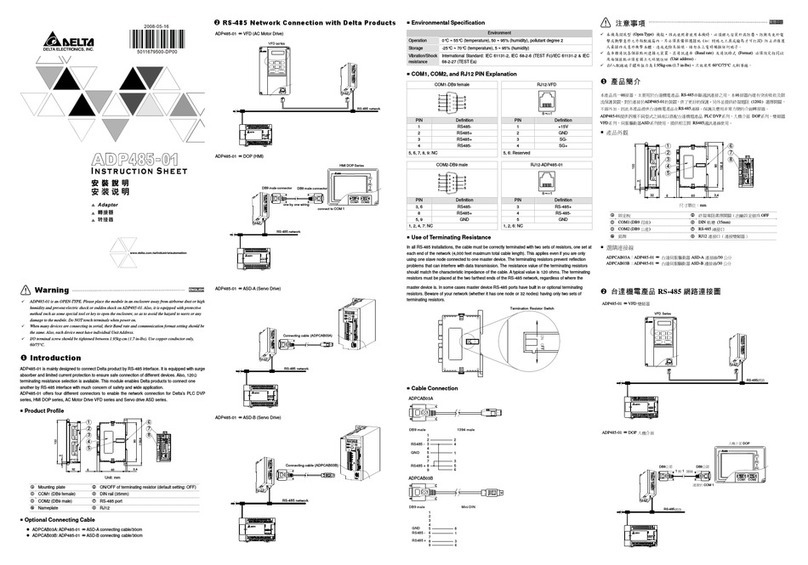
Delta Electronics Network Device ADP485-01 instruction manual
Pittway
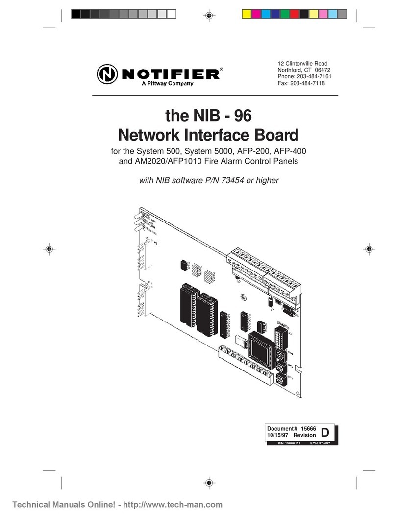
Pittway Notifier NIB-96 manual
NEXTIVITY
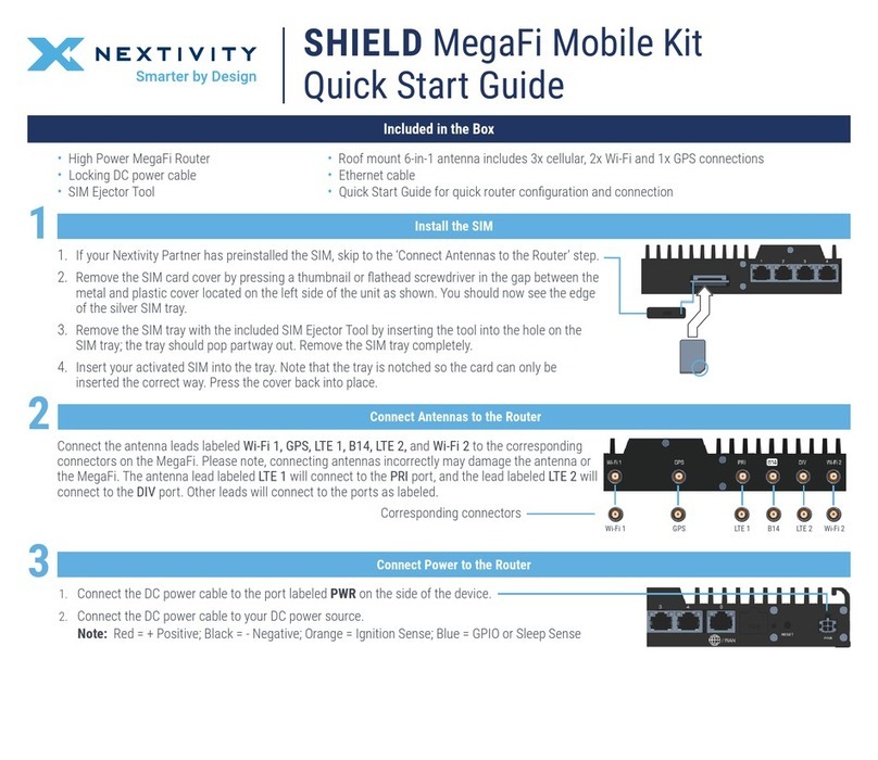
NEXTIVITY SHIELD MegaFi quick start guide
AVE
AVE ATM Interface TCPIP232 Operation manual
Panasonic
Panasonic Transistors 2SC5846 Specifications
Alcatel-Lucent
Alcatel-Lucent VitalQIP AMS 1000 quick start guide
