Connective Peripherals ES-U Series User manual

Connective Peripherals Pte Ltd
178 Paya Lebar Road, #07-03 Singapore 409030
Tel.: +65 67430980 Fax: +65 68416071
Neither the whole nor any part of the information contained in, or the product described in this manual, may be adapted, or reproduced
in any material or electronic form without the prior written consent of the copyright holder. This product and its documentation are
supplied on an as-is basis and no warranty as to their suitability for any particular purpose is either made or implied. Connective
Peripherals Pte Ltd will not accept any claim for damages howsoever arising as a result of use or failure of this product. Your statutory
rights are not affected. This product or any variant of it is not intended for use in any medical appliance, device, or system in which the
failure of the product might reasonably be expected to result in personal injury. This document provides preliminary informat ion that
may be subject to change without notice. No freedom to use patents or other intellectual property rights is implied b y the publication of
this document. Connective Peripherals Pte Ltd, 178 Paya Lebar Road, #07-03 Singapore 409030. Registered Number: 201617872E
Copyright © Connective Peripherals Pte Ltd
The ES-U-xxxx-x adapters are a series of USB Serial Converters from Connective Peripherals Pte
Ltd. They provide a simple method of adapting legacy RS-232 or RS-422/485 devices to work
with modern USB ports using a trusted and reliable FTDI chip set. Available in a variety of
enclosures and port numbers, they are ideal for allowing factory automation equipment, multi-
drop data collection devices, barcode readers, time clocks, scales, data entry terminals and
serial communication equipment to be connected to USB ports in industrial environments.
This manual covers the following USB to Serial Converter products. For older products from the
ES-U-xxxx-xx series please refer to the earlier version 1.4 of this manual available from the
Connective Peripherals website.
ES-U-1001-A
ES-U-1032-RM
ES-U-2002-M
ES-U-2101-MB
ES-U-1101-MB
ES-U-2001B
ES-U-2102-M
ES-U-3001-MB
ES-U-1002-A
ES-U-2101B
ES-U-2104-M
ES-U-3008-RM
ES-U-1002-M
ES-U-2001C
ES-U-2008-M
ES-U-3008-RMB
ES-U-1008B
ES-U-2101C
ES-U-2016-RM
ES-U-3016-RM
Connective Peripherals Pte Ltd
USB to Serial Converters Manual
Document Reference No.: CP_000032
Version 2.1
Issue Date: 01-04-2022

USB to Serial Converters Manual
Version 2.1
Document Reference No.: CP_000032 Clearance No.: CP#022
Copyright © Connective Peripherals Pte Ltd 2
Table of Contents
1Introduction.................................................................... 4
2Specifications.................................................................. 5
2.1 Standard Features .................................................................... 5
2.2 Features by Model..................................................................... 6
3Features of the ES-U-xxxx-x Family ................................ 7
3.1 USB and Serial Interface ........................................................... 7
3.2 Case Styles ............................................................................... 8
3.3 Power Supply............................................................................ 9
3.4 Optical Isolation & Surge Protection ....................................... 10
3.5 Configuring for RS-232, RS-422 and RS-485 Modes ................ 10
4Switch and Jumper Settings.......................................... 12
4.1 General Notes and Warnings................................................... 12
4.2 ES-U-2x01B / ES-U-2x01C Adapters (Plastic Enclosure)......... 13
4.3 ES-U-2xxx-M and ES-U-2xxx-RM with 3 DIP Switches ............ 14
4.4 ES-U-2xxx-M with 4 DIP Switches .......................................... 15
4.5 ES-U-3xxx-x and ES-U-2101-MB ............................................. 16
5Connector Pinout Information....................................... 18
5.1 RS-232 Signal Pin-out ............................................................. 18
5.2 RS-422 Signal Pin-out ............................................................. 19
5.3 RS-485 Signal Pin-out (Half Duplex)....................................... 21
5.4 RS-485 Signal Pin-out (Full Duplex) ....................................... 23
5.5 5V Power Output (ES-U-1002-M only) .................................... 24
6Driver Installation......................................................... 25
7Troubleshooting ............................................................ 26
7.1 Hardware ................................................................................ 26
7.2 Drivers .................................................................................... 27
8Contact Information...................................................... 28
Appendix A - List of Figures and Tables ............................. 29
List of Figures ................................................................................. 29
List of Tables ................................................................................... 29

USB to Serial Converters Manual
Version 2.1
Document Reference No.: CP_000032 Clearance No.: CP#022
Copyright © Connective Peripherals Pte Ltd 4
1Introduction
The ES-U-xxxx-x family of converters provide a quick and simple way to add serial communication ports
to your computer. They connect to a single USB port on your computer to instantly provide up to 32
serial ports. They take advantage of the plug-and-play and hot-plug features of the USB bus to make it
easier than ever to add communication ports to your system.
Installation is easy. There are no IRQ & COM port conflicts as the port doesn't require any additional IRQ,
DMA or memory resources on the system. Each RS-232 or RS-422/RS-485 port functions as a native
Windows COM port and is compatible with Windows serial communication applications.
The ES-U-xxxx-x converters provide instant connectivity to RS-232 or RS-422/RS-485 compatible
devices, including factory automation equipment, multi-drop data collection devices, barcode readers,
time clocks, point of sale, scales, data entry terminals and a variety of other devices in industrial
environments.
This manual covers the following models:
USB to RS-232 converters
•Single channel (ES-U-1001-A, ES-U-1101-MB)
•Dual channel (ES-U-1002-A, ES-U-1002-M)
•8-channel (ES-U-1008B)
•32-channel (ES-U-1032-RM)
USB to RS-422/485 converters
•Single channel (ES-U-2001B, ES-U-2101B, ES-U-2001C, ES-U-2101C)
•Dual channel (ES-U-2002-M, ES-U-2102-M)
•Quad channel (ES-U-2104-M)
•8-channel (ES-U-2008-M)
•16-channel (ES-U-2016-RM)
USB to RS-232/422/485 converters
•Single channel (ES-U-3001-MB, ES-U-2101-MB)
•8-channel (ES-U-3008-RM, ES-U-3008-RMB)
•16-channel (ES-U-3016-RM)

USB to Serial Converters Manual
Version 2.1
Document Reference No.: CP_000032 Clearance No.: CP#022
Copyright © Connective Peripherals Pte Ltd 5
2Specifications
2.1 Standard Features
•Internal Transmit and Receive buffers
•Requires no IRQ, DMA, I/O port
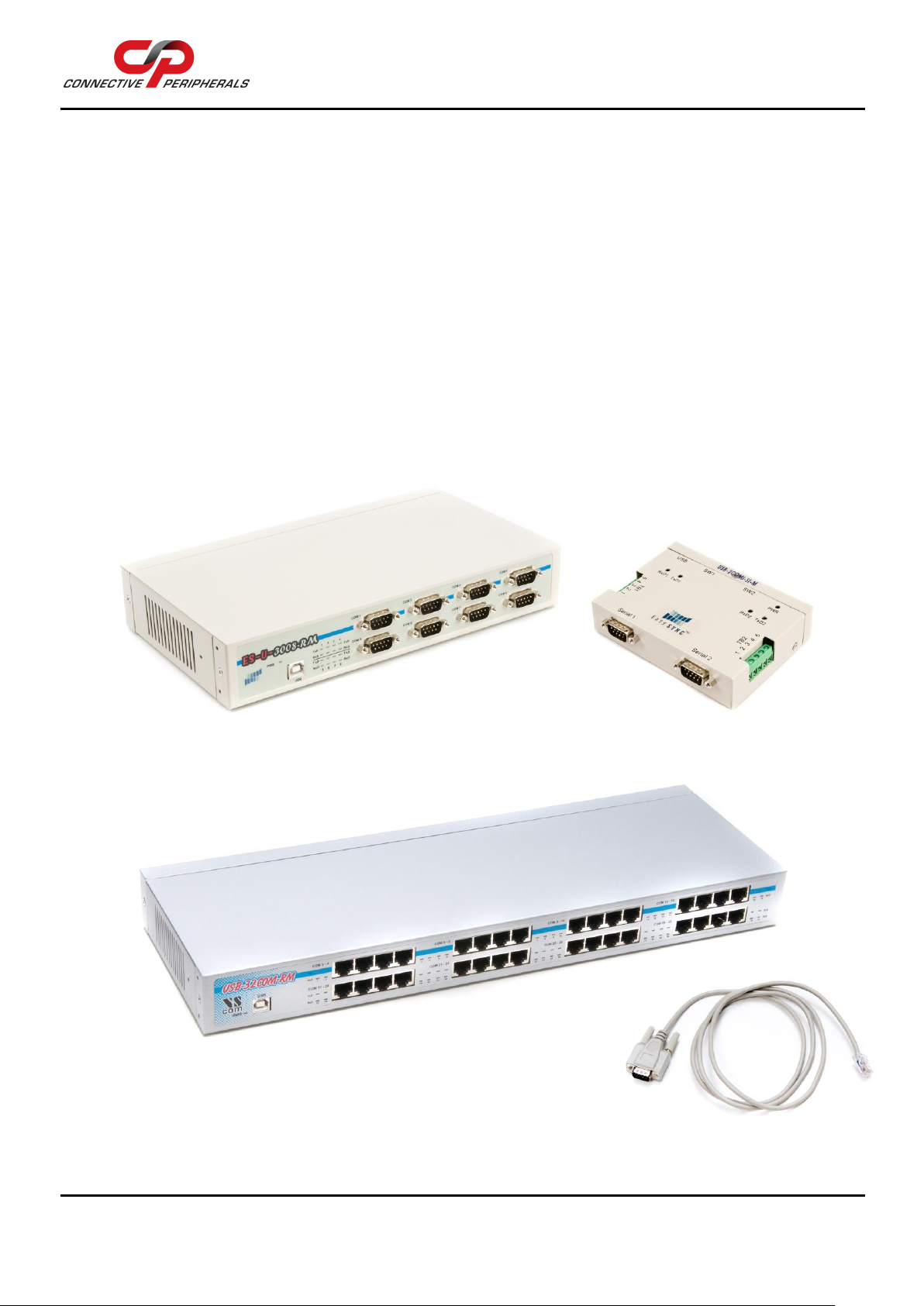
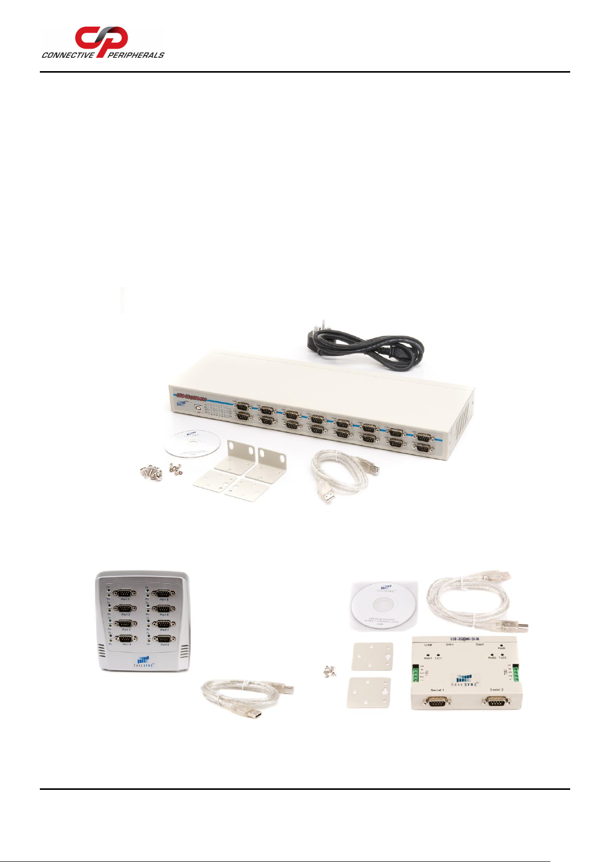
•DB-9 male serial connectors (terminal blocks on some models) (see Note 1)
•LEDs for each port indicate TxD and RxD
•Virtual COM port drivers available
oWindows 7 up to Windows 11
oMAC OSX 10.9 onwards
oLinux Kernel 3.0.0-19 onwards (e.g., Ubuntu version 11.10)
oOther legacy drivers available from the FTDI website
USB to RS-232 Features (available on ES-U-1xxx, ES-U-30xx and ES-U-2101-MB)
•Adds RS-232 ports via USB connection
•RS-232 data signals: DCD, RxD, TxD, DTR, GND, DSR, RTS, CTS, RI (see Note 2)
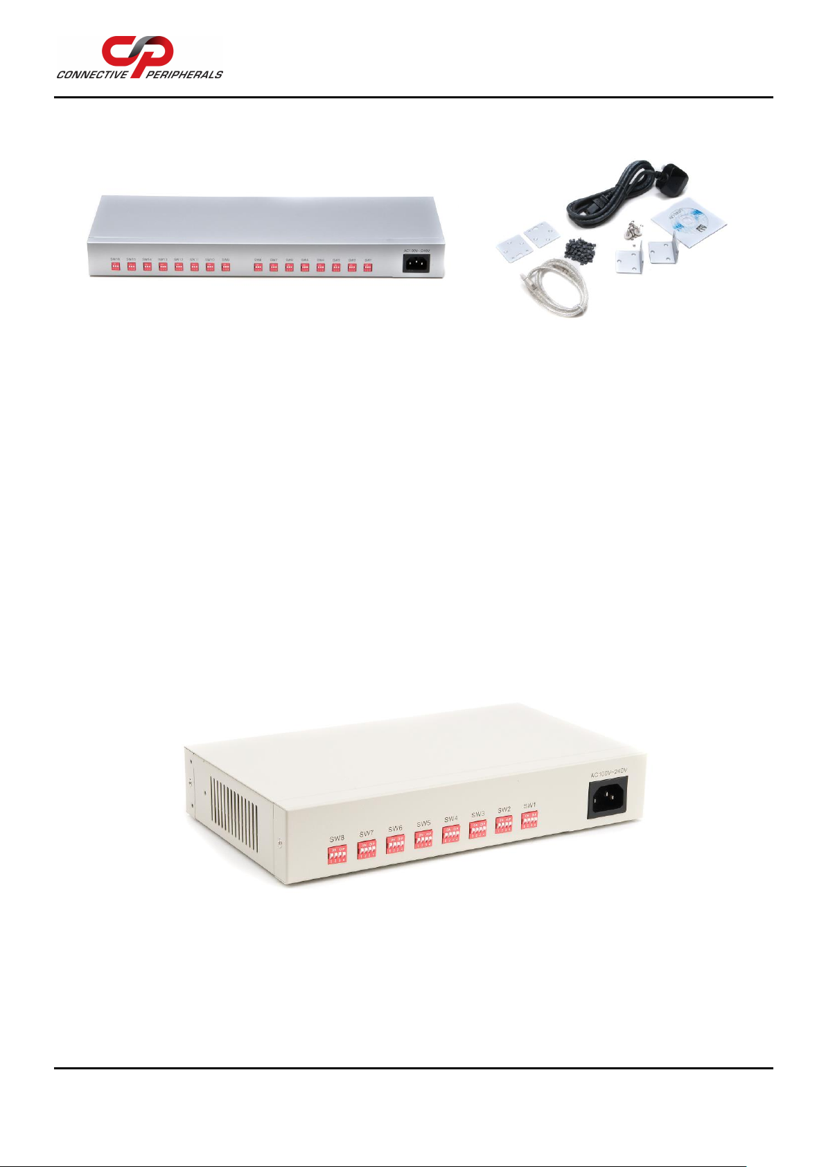
USB to RS-422/RS-485 Features (available on ES-U-20xx and ES-U-30xx) (see Note 3)
•Adds RS-422 / RS-485 ports via USB connection
•Auto transmit buffer control for 2-wire RS-485 half-duplex operation
•Internal termination and bias resistors on some models (enabled by jumper)
•RS-422 data signals: TX-, TX+, RX+, RX-, GND, RTS-, RTS+, CTS+, CTS- (see Note 2)
•RS-485 signals (half duplex): Data+, Data-, GND
•RS-485 signals (full-duplex): TX-, TX+, RX-, RX+, GND
Additional Opto-isolation Features (available on ES-U-11xx and ES-U-21xx)
•Each RS-232 or RS-422/RS-485 port is individually isolated with 2000-volt DC optical isolation
•Each RS-232 or RS-422/RS-485 port is individually protected by a surge protector to withstand
electrostatic discharge and power surges up to 25KV ESD
Note 1 ES-U-1032-RM has RJ45 ports which can be converted to DB-9 male if required using the supplied cables
Note 2 Terminal block has subset of these signals only –see section Error! Reference source not found. for
details
ES-U-2101-MB also features RS232 but only a subset of these signals –see section Error! Reference
source not found. for details
Note 3 Supports multiple serial protocols - Jumpers or DIP switches are used to select the required serial protocol

USB to Serial Converters Manual
Version 2.1
Document Reference No.: CP_000032 Clearance No.: CP#022
Copyright © Connective Peripherals Pte Ltd 6
2.2 Features by Model
Table 1 summarises the features for each model in the ES-U-xxxx-x family.
Table 1 - Features of the ES-U-xxxx-x converters
Power supply types are USB (USB powered), Ext (external power adapter) or Int (internal power supply)
* Power adapter voltages and currents shown in the comments column is for indication only and are
subject to change. To avoid damage, always use the adapter which was provided with your converter to
ensure that you are supplying the correct voltage for operation.
Model Number
Serial Interfaces
Case
Power
Supply
Opto
Isolated
Additional features and
Notes
Ports
RS232
RS422
RS485
Metal
Rack
ES-U-1001-A
1
Y
-
-
-
-
USB
-
ES-U-1101-MB
1
Y
-
-
Y
-
USB
Y
Revision B of ES-U-1101-M
which supports higher data
throughput
ES-U-1002-A
2
Y
-
-
-
-
USB
-
ES-U-1002-M
2
Y
-
-
Y
-
USB
-
5V 150mA output on 2-way
screw terminal
ES-U-1008B
8
Y
-
-
-
-
USB
-
ES-U-1032-RM
32
Y
-
-
Y
Y
Int
-
RJ45 serial connectors
ES-U-2001B
1
-
Y
Y
-
-
USB
-
Rev B of ES-U-2001
ES-U-2001C
1
-
Y
Y
-
-
USB
-
Rev C of ES-U-2001
ES-U-2101B
1
-
Y
Y
-
-
USB
Y
Rev B of ES-U-2101
ES-U-2101C
1
-
Y
Y
-
-
USB
Y
Rev C of ES-U-2101
ES-U-2101-MB
1
Y
Y
Y
Y
-
USB
Y
6-way screw terminal
ES-U-2002-M
2
-
Y
Y
Y
-
USB
-
5-way screw terminals
ES-U-2102-M
2
-
Y
Y
Y
-
USB
Y
ES-U-2002-M with isolation
ES-U-2104-M
4
-
Y
Y
Y
-
Ext
Y
5VDC (2A) power adapter
(barrel plug) *
ES-U-2008-M
8
-
Y
Y
Y
-
Ext
-
12VDC (1.5A) power adapter
(3-pin terminal) *
ES-U-2016-RM
16
-
Y
Y
Y
Y
Int
-
ES-U-3001-MB
1
Y
Y
Y
Y
-
USB
-
6-way screw terminal, 5V
output
Rev B of ES-U-3001-M which
supports higher data
throughput
ES-U-3008-RM
8
Y
Y
Y
Y
Y
Int
-
ES-U-3008-RMB
8
Y
Y
Y
Y
Y
Ext
-
Rev B with external 5V PSU
ES-U-3016-RM
16
Y
Y
Y
Y
Y
Int
-

USB to Serial Converters Manual
Version 2.1
Document Reference No.: CP_000032 Clearance No.: CP#022
Copyright © Connective Peripherals Pte Ltd 7
3Features of the ES-U-xxxx-x Family
3.1 USB and Serial Interface
USB Interface
Devices in the ES-U-xxxx-x series feature a standard USB type-B socket (with standard USB A-B cable
supplied to connect to the PC) or a USB type-A plug to connect to the USB port directly.
Serial Interface
The ES-U-xxxx-x converters have DB-9 male connectors for connection to the RS-232/422/485 interface.
Some models have the following additional features:
•Terminal block connections providing a subset of the signals
•Optional 5V output.
The ES-U-1032-RM unit has RJ45 connectors on the front panel instead of DB-9, but is provided with
adapter cables to convert these to DB-9 male connectors if required.
Figure 1 - DB-9 Male serial connectors. Some models also feature terminal blocks
Figure 2 - ES-U-1032-RM (RJ45 connectors) is supplied with RJ45-to-DB-9 cables
ES-U-3008-RM
ES-U-2102-M
ES-U-1032-RM

USB to Serial Converters Manual
Version 2.1
Document Reference No.: CP_000032 Clearance No.: CP#022
Copyright © Connective Peripherals Pte Ltd 8
3.2 Case Styles
The ES-U-xxxx-x converters are available in Plastic, Metal and Metal Rackmount enclosure styles. All
units can be used on a desktop with the self-adhesive feet provided.
•Plastic case desktop converters are supplied with USB cable (except ES-U-1001-A and ES-U-
1002-A) and a power adapter localised to country of sale (when required depending on model).
•Metal case converters are supplied with wall mounting hardware, USB cable and power adapter
with plug localised to country of sale (when required depending on model).
•Metal rack mount converters are supplied with rack mounting hardware, USB cable and power
cable or power adapter localised to country of sale.
Transmit and receive LEDs for each port are included on the front or top panel of the enclosure, to show
when data is being transmitted or received by the associated port. A power LED is also included (on units
with metal enclosures) to show that the converter is receiving power.
Note that enclosure colour may vary from the photos shown. Some models with metal enclosures are
changing to a black colour
Figure 3 - Example of the Metal Rack-mount enclosure
Figure 4 - Examples of the Plastic and Metal (wall mountable) enclosures
ES-U-1016-RM
ES-U-1008B
ES-U-2102-M

USB to Serial Converters Manual
Version 2.1
Document Reference No.: CP_000032 Clearance No.: CP#022
Copyright © Connective Peripherals Pte Ltd 9
3.3 Power Supply
Depending on the model, power will either be supplied from the USB port, from an external power
adapter or from an internal switching supply. The different types are described below. Table 1 on page 6
shows which type of power supply is required for each converter model.
USB powered
These devices are powered directly from the USB port. No power supply is required for these converters.
It is recommended to connect them direct to a PC’s USB port. If necessary to use a USB hub, it is
strongly recommended to use a self-powered hub (which has its own PSU) as bus-powered hubs may not
be able to provide sufficient power.
Power Adapter
These devices are provided with an external power adapter in the package. The adapter supplied has a
UK, EU or USA plug depending on the country of sale and so may vary from the one shown below. The
low voltage connector is either a 3-pin terminal block connector or a barrel-type jack as shown below,
depending on the model. For more details, see Table 1 on page 6.
The low voltage cable should be connected to the power (or DC in) socket on the converter, and the AC
input plug should be connected to a power source before using the converter.
Always use the supplied adapter to power your ES-U-xxxx-x converter; damage will occur if an
adapter providing the wrong voltage is used and is not covered by the warranty.
Figure 5 - Some models use a power adapter with barrel or terminal connector
The revision B of the rack-mountable units now also have external power supplies and use the connector
shown in Figure 6.
Figure 6 –ES-U-3008-RMB power connector
Internal Switching Power Supply
The rack mountable (ES-U-xxxx-RM) devices require an AC input (100V ~ 240V, 47 –63 Hz) for the
internal switching power supply. A power cable is supplied with the converter and connects to the power
inlet socket on the rear panel. The cable has a UK, EU or USA plug depending on the country of sale and
so may vary from the one shown below.
Barrel Plug
connector
Terminal
Block
connector
ES-U-2108-M
ES-U-2008-M

USB to Serial Converters Manual
Version 2.1
Document Reference No.: CP_000032 Clearance No.: CP#022
Copyright © Connective Peripherals Pte Ltd 10
Note that the revision B rack-mountable units (such as ES-U-3008-RMB) now have an external power
supply instead of the internal power supply, and uses the connector shown in the Power Adapter section
above in Figure 6.
Figure 7 - Rack-mount model with an internal supply with AC input connector
3.4 Optical Isolation & Surge Protection
Optical isolation and surge protection are available in the ES-U-11xx and ES-U-21xx converters.
Each serial port is individually optically isolated with 2000-volt DC optical isolation. The optical isolation
protects your PC or notebook from spikes and surges on the RS-232 or RS-422/RS-485 network, by
converting the electrical data into an optical signal and then changing it back into electrical data. Your
computer is well protected since the surges and spikes cannot cross the optical link.
Each serial port is individually protected by surge protector to withstand electrostatic discharge and
power surges up to 25KV ESD.
3.5 Configuring for RS-232, RS-422 and RS-485 Modes
The ES-U-2xxx-x and ES-U-3xxx-x converters can be configured for different interface types. These
converters have DIP switches or internal jumpers to select the required interface. They also feature
internal jumpers to select options such as termination and biasing of the RS-422 and RS-485 lines.
Please refer to section 4 for more information on the DIP switch and jumper settings available on each
model of converter.
Figure 8 - ES-U-2xxx and ES-U-3xxx have DIP switches to select the serial mode
ES-U-2016-RM
ES-U-3008-RM

USB to Serial Converters Manual
Version 2.1
Document Reference No.: CP_000032 Clearance No.: CP#022
Copyright © Connective Peripherals Pte Ltd 11
Figure 9 - ES-U-3008-RM has a set of jumpers for each port (one set circled)

USB to Serial Converters Manual
Version 2.1
Document Reference No.: CP_000032 Clearance No.: CP#022
Copyright © Connective Peripherals Pte Ltd 12
4Switch and Jumper Settings
This section applies to ES-U-2xxx-x and ES-U-3xxx-x converters, which can be configured for different
interface types. These converters have DIP switches and internal jumpers to select the required interface.
The following pages give details of the settings required for each model of converter. Ensure that you
refer to the correct section for your model of converter. The relevant model numbers are listed at the top
of each section. Always read the general notes and warnings on this page before proceeding to configure
your device.
4.1 General Notes and Warnings
Safety
For ES-U-xxxx-RM models with internal power supplies, the power cable must be disconnected
before removing the cover. Opening the cover will expose connections and boards carrying lethal
voltages. Contact with these will cause severe injury or death. In common with all switching
power supplies connected to the mains (120/240VAC), the power supply board in these products
can remain charged with dangerous voltages for some time after the power input is disconnected
and so avoid contact with the power supply board inside the converter even when un-powered.
Serial Bus Configuration
It is important to configure the DIP switches and jumpers to select the correct type of serial bus (RS-232,
RS-422 or RS-485) for your application before connecting the ES-U-xxxx-x converter to your serial bus.
Otherwise, damage can occur to the converter or other equipment on the RS-232/RS-422/RS-485 bus.
To avoid damage, the power supply (or power cable in rack-mount units), serial cables and USB cable
should be disconnected from your converter before changing DIP switch settings and before opening the
case to change jumper settings.
Termination
For RS-422 or RS-485, it may be necessary to enable termination of the data transmission lines. This
depends on the way in which your network is connected and if termination is already provided by other
devices on the network. Before applying the termination, check your cable specification for proper
impedance matching. The termination option connects a 120 Ohm resistor between the data + and -
lines. Termination is not needed for RS232 and may affect the signals if enabled.
Termination is normally used in the node at each end of the bus, but nodes in the middle of the bus
should not have termination enabled. Enabling termination resistors on additional nodes which are not at
the ends of the bus may cause overloading of the line drivers leading to unreliable operation of the unit
and the overall system.
The ES-U-xxxx-x converters have jumpers (or DIP switches) to allow internal termination resistors to be
enabled if required. This avoids the need to provide an external resistor at the ES-U-xxxx-x end of the
bus.
ES-U-xxxx-x converters have separate jumpers/switches for Tx+/Tx- termination and Rx+/Rx-
termination allowing termination to be enabled for either or both if required. The product-specific sections
throughout chapter 4 describe these in more detail. When using RS-485 half-duplex, the Tx and Rx pairs
are combined into a single bi-directional pair and so only the Tx+/Tx- termination should be enabled. The
Rx+/Rx- termination should be disabled.
Biasing
In some cases, the RS-485 lines may float to undefined levels when no transmitter is active, and this can
cause additional unexpected characters to appear at the start or end of a message. Biasing resistors are
used to set a defined logic level on the serial lines when no node is transmitting. 750 Ohm resistors pull
up the Data + line and pull down the Data –line.
Some ES-U-xxxx-x models feature internal 750-ohm resistors with jumpers to enable/disable them.

USB to Serial Converters Manual
Version 2.1
Document Reference No.: CP_000032 Clearance No.: CP#022
Copyright © Connective Peripherals Pte Ltd 13
These should be disabled if another device on your serial bus already provides biasing as biasing of data
lines must only occur at a single point in the cabling. Fitting more than one set of bias resistors can cause
overloading of the line drivers leading to unreliable operation of the unit and the overall system. Biasing
is not required for RS232 and may affect the signals if enabled.
ES-U-xxxx-x converters have four jumpers to select biasing on Tx+, Tx-, Rx+ and Rx-. The product-
specific sections throughout chapter 4 describe these in more detail. When using RS-485 half-duplex, the
Tx and Rx pairs are combined into a single bi-directional pair and so only the jumpers for Tx biasing (Pull
up of Tx+ and Pull down of Tx-) should be fitted. The Rx biasing should be disabled.
4.2 ES-U-2x01B / ES-U-2x01C Adapters (Plastic Enclosure)
This section applies to the following adapters:
•ES-U-2001B (see note below)
•ES-U-2001C (see note below)
•ES-U-2101B (see note below)
•ES-U-2101C (see note below)
Note: This section applies only to revision B and C units which have the part numbers listed above. For
the original ES-U-2001 and ES-U-2101, please refer to version 1.4 of this guide which is available from
the Connective Peripherals website.
This section does not apply to ES-U-2xxx-M (metal case) adapters. Please see sections 4.3 and 4.4 for
these products.
See the General Notes and Warnings on page 12 before changing settings or opening the cover.
The jumpers should be set to select the correct serial mode before connecting the converter to
your RS-422/RS-485 serial bus.
DIP Switch Settings
On the inside of the unit, there are three DIP switches, which are used to select the required serial mode
(RS-422 or RS-485).
Operation Mode
S1
S2
S3
RS-422
4 Wire with handshaking
ON
ON
ON
RS-485
Full Duplex (4 wire)
OFF
ON
ON
Half Duplex (2 wire) with Echo
OFF
OFF
ON
Half Duplex (2 wire) without Echo
OFF
OFF
OFF
Table 2 - RS-422 & RS-485 Mode Configuration
Jumper Settings
Inside the unit, there is a 7x3 (21 pin) header block. Jumpers are used to select features such as 120
Ohm termination on Tx, Rx and CTS, and 750 Ohm biasing resistors on Tx and Rx. You will need to open
the cover and set the jumpers as per the requirements of your application.
Jumper
Function
1 - 2
Enable Tx+/- Termination with 120 Ohm (see notes below table)
2 –3
Disable Tx+/- Termination
4 –5
Enable Tx Bias - Pull-up Tx+ to VCC by 750 Ohm Bias resistor (see notes below table)
5 –6
Disable Pull-up of Tx+ to VCC
7 –8
Enable Pull-down of Tx- to GND by 750 Ohm Bias resistor (see notes below table)
8 –9
Disable Pull-down of Tx- to GND

USB to Serial Converters Manual
Version 2.1
Document Reference No.: CP_000032 Clearance No.: CP#022
Copyright © Connective Peripherals Pte Ltd 14
10 - 11
Enable Rx+/- Termination with 120 Ohm (see notes below table)
11 –12
Disable Rx+/- Termination
13 –14
Enable Pull-up of Rx+ to VCC by 750 Ohm Bias resistor (see notes below table)
14 –15
Disable Pull-up of Rx+ to VCC
16 –17
Enable Pull-down of Rx- to GND by 750 Ohm Bias resistor (see notes below table)
17 –18
Disable Pull-down of Rx- to GND
19 –20
Enable CTS Termination with 120 Ohm (populate for RS422 mode if termination is
required)
20 - 21
Disable CTS Termination
Table 3 - Jumpers to select Termination and Biasing
Note on Termination:
For RS485 half-duplex, if termination is required, only Tx Termination should be enabled as the Tx and
Rx lines are linked. Enable Tx+/- termination (jumper 1-2) and disable Rx+/- termination (jumper 11-
12).
For RS485 full-duplex and RS422, termination can be enabled/disabled for Tx+/- and Rx+/- pairs
independently using the jumpers as required. See the notes on Termination in section 4.1 before setting
these options
Note on Biasing:
For RS485 half-duplex, if biasing is required, enable Tx+/- biasing only (jumper 4-5 and 7-8) and disable
Rx+/- biasing (jumper 14-15 and 17-18).
For RS485 full-duplex and RS422, biasing can be enabled/disabled for Tx+/- and Rx+/- pairs
independently as required. See the notes on Biasing in section 4.1 before setting these options.
4.3 ES-U-2xxx-M and ES-U-2xxx-RM with 3 DIP Switches
This section applies to the following adapters:
•ES-U-2002-M
•ES-U-2102-M
•ES-U-2008-M
•ES-U-2016-RM
See the General Notes and Warnings on page 12 before changing settings or opening the cover.
The DIP switches should be set to select the correct serial mode before connecting the converter
to your RS-422/RS-485 serial bus.
DIP Switch Settings
On the outside of the unit, there are three DIP switches, which are used to select the required serial
mode (RS-422 or RS-485).
Operation Mode
S1
S2
S3
RS-422
4 Wire with handshaking
ON
ON
ON
RS-485
Full Duplex (4 wire)
OFF
ON
ON
Half Duplex (2 wire) with Echo
OFF
OFF
ON
Half Duplex (2 wire) without Echo
OFF
OFF
OFF
Table 4 - RS-422 & RS-485 Mode Configuration

USB to Serial Converters Manual
Version 2.1
Document Reference No.: CP_000032 Clearance No.: CP#022
Copyright © Connective Peripherals Pte Ltd 15
Jumper Settings
Inside the unit, there is a 7x2 (14 pin) header block for each serial port. Jumpers are used to select
features such as 120 Ohm termination on Tx, Rx and CTS, and 750 Ohm biasing resistors on Tx and Rx.
You will need to open the cover and set the jumpers as per the requirements of your application.
Jumper
Function
1 –2
Enable Tx+/- Termination with 120 Ohm (see notes below table)
3 –4
Enable Tx Bias –Pull-up Tx+ to VCC by 750 Ohm Bias resistor (see notes below table)
5 –6
Enable Tx Bias –Pull-down Tx- to GND by 750 Ohm Bias resistor (see notes below table)
7 –8
Enable Rx+/- Termination with 120 Ohm (see notes below table)
9 –10
Enable Rx Bias –Pull-up Rx+ to VCC by 750 Ohm Bias resistor (see notes below table)
11 –12
Enable Rx Bias –Pull-down Rx- to GND by 750 Ohm Bias resistor (see notes below
table)
13 –14
Enable CTS Termination with 120 Ohm (populate for RS422 mode if termination is
required)
Table 5 –Jumpers to select Termination and Biasing
Note on Termination:
For RS485 half-duplex, if termination is required, only Tx Termination should be enabled as the Tx and
Rx lines are linked. Enable Tx+/- termination (jumper 1-2) and disable Rx+/- termination (leave jumper
7-8 open)
For RS485 full-duplex and RS422, termination can be enabled/disabled for Tx+/- and Rx+/- pairs
independently using the jumpers as required. See the notes on Termination in section 4.1 before setting
these options
Note on Biasing:
For RS485 half-duplex, if biasing is required, enable Tx+/- biasing only (jumper 3-4 and 5-6) and disable
Rx+/- biasing (leave jumper 9-10 and 11-12 open)
For RS485 full-duplex and RS422, biasing can be enabled/disabled for Tx+/- and Rx+/- pairs
independently as required. See the notes on Biasing in section 4.1 before setting these options
4.4 ES-U-2xxx-M with 4 DIP Switches
This section applies to the following adapters:
•ES-U-2104-M
See the General Notes and Warnings on page 12 before changing settings or opening the cover.
The DIP switches should be set to select the correct serial mode before connecting the converter
to your RS-422/RS-485 serial bus.
DIP Switch Settings
On the outside of the unit, there are four DIP switches, which are used to select the required serial mode
(RS-422 or RS-485).
Operation Mode
S1
S2
S3
S4
RS-422
4 Wire with handshaking
ON
ON
OFF
OFF
RS-485
Full Duplex (4 wire)
ON
OFF
OFF
OFF
Half Duplex (2 wire) with Echo
OFF
OFF
OFF
ON
Half Duplex (2 wire) without Echo
OFF
OFF
ON
ON
Table 6 - RS-422 & RS-485 Mode Configuration

USB to Serial Converters Manual
Version 2.1
Document Reference No.: CP_000032 Clearance No.: CP#022
Copyright © Connective Peripherals Pte Ltd 16
Switch S4 selects 120R termination of TxD. It is normally enabled for half-duplex RS-485 modes but may
not be required if both ends of your network are already terminated.
Jumper Settings
Inside the unit, there is a 6x2 (12 pin) header block for each serial port. Jumpers are used to select
features such as 120 Ohm termination on Rx and CTS, and 750 Ohm biasing resistors on Tx and Rx. You
will need to open the cover and set the jumpers as per the requirements of your application.
Jumper
Function
1 - 2
Enable Tx Bias - Pull-up Tx+ to VCC by 750 Ohm Bias resistor (see notes below table)
3 - 4
Enable Tx Bias - Pull-down Tx- to GND by 750 Ohm Bias resistor (see notes below table)
5 - 6
Enable Rx+/- Termination with 120 Ohm (see notes below table)
7 - 8
Enable Rx Bias - Pull-up Rx+ to VCC by 750 Ohm Bias resistor (see notes below table)
9 - 10
Enable Rx Bias - Pull-down Rx- to GND by 750 Ohm Bias resistor (see notes below table)
11 - 12
Enable CTS Termination with 120 Ohm (populate for RS422 mode if termination is
required)
Table 7 - Jumpers to select Termination and Biasing
Note on Termination:
For RS485 half-duplex, if termination is required, only Tx Termination should be enabled as the Tx and
Rx lines are linked. Enable Tx+/- termination (using DIP switch 4 on this model) and disable Rx+/-
termination (leave jumper 5-6 open)
For RS485 full-duplex and RS422, termination can be enabled/disabled for Tx+/- and Rx+/- pairs
independently using the jumpers as required. See the notes on Termination in section 4.1 before setting
these options
Note on Biasing:
For RS485 half-duplex, if biasing is required, enable Tx+/- biasing only (jumper 1-2 and 3-4) and disable
Rx+/- biasing (leave jumper 7-8 and 9-10 open).
For RS485 full-duplex and RS422, biasing can be enabled/disabled for Tx+/- and Rx+/- pairs
independently as required. See the notes on Biasing in section 4.1 before setting these options
4.5 ES-U-3xxx-x and ES-U-2101-MB
This section applies to the following adapters:
•ES-U-3001-MB
•ES-U-3008-RM
•ES-U-3016-RM
•ES-U-2101-MB
See the General Notes and Warnings on page 12 before changing settings or opening the cover.
The DIP switches should be set to select the correct serial mode before connecting the converter
to your RS-232/RS-422/RS-485 serial bus.
DIP Switch Settings
On the outside of the unit, there are four DIP switches, which are used to select the required serial mode
(RS-232, RS-422 or RS-485).
Operation Mode
S1
S2
S3
S4
RS-232
OFF
ON
ON
ON

USB to Serial Converters Manual
Version 2.1
Document Reference No.: CP_000032 Clearance No.: CP#022
Copyright © Connective Peripherals Pte Ltd 17
RS-422
4 Wire with handshaking
ON
ON
ON
ON
RS-485
Full Duplex (4 wire)
ON
OFF
ON
ON
Half Duplex (2 wire) with Echo
ON
OFF
OFF
ON
Half Duplex (2 wire) without Echo
ON
OFF
OFF
OFF
Table 8 - RS-232, RS-422 & RS-485 Mode Configuration
Jumper Settings
Inside the unit, there is a 7x2 (14 pin) header block for each serial port. Jumpers are used to select
features such as 120 Ohm termination on Tx, Rx and CTS, and 750 Ohm biasing resistors on Tx and Rx.
You will need to open the cover and set the jumpers as per the requirements of your application.
Jumper
Function
1 - 2
Enable Tx+/- Termination with 120 Ohm (see notes below table)
3 - 4
Enable Tx Bias - Pull-up Tx+ to VCC by 750 Ohm Bias resistor (see notes below table)
5 - 6
Enable Tx Bias - Pull-down Tx- to GND by 750 Ohm Bias resistor (see notes below table)
7 - 8
Enable Rx+/- Termination with 120 Ohm (see notes below table)
9 - 10
Enable Rx Bias - Pull-up Rx+ to VCC by 750 Ohm Bias resistor (see notes below table)
11 - 12
Enable Rx Bias - Pull-down Rx- to GND by 750 Ohm Bias resistor (see notes below table)
13 - 14
Enable CTS Termination with 120 Ohm (populate for RS422 mode if termination is
required)
Table 9 - Jumpers to select Termination and Biasing
Note on Termination:
For RS485 half-duplex, if termination is required, only Tx Termination should be enabled as the Tx and
Rx lines are linked. Enable Tx+/- termination (jumper 1-2) and disable Rx+/- termination (leave jumper
7-8 open)
For RS485 full-duplex and RS422, termination can be enabled/disabled for Tx+/- and Rx+/- pairs
independently using the jumpers as required. See the notes on Termination in section 4.1 before setting
these options
Note on Biasing:
For RS485 half-duplex, if biasing is required, enable Tx+/- biasing only (jumper 3-4 and 5-6) and disable
Rx+/- biasing (leave jumper 9-10 and 11-12 open)
For RS485 full-duplex and RS422, biasing can be enabled/disabled for Tx+/- and Rx+/- pairs
independently as required. See the notes on Biasing in section 4.1 before setting these options
5V Power Enable Jumper (ES-U-3001-MB and ES-U-2101-MB)
The ES-U-3001-MB and ES-U-2101-MB can supply 5V (at up to 150mA) through Pin 5 of the terminal
block to allow external devices to be powered. To enable the power, you need to open the metal case and
set the jumper (JP2) to the position of “ON”.
Jumper
Function
ON
Enable the 5V 150mA output on pin 5 of the Terminal Block to provide
power for external devices
OFF
Disable the 5V 150mA power (Default)
Table 10 - Jumper to select 5V output
RS232 Pin-Out (ES-U-2101-MB)
The ES-U-2101-MB has only a subset of the signals on the DB-9 connector to provide TxD, RxD, RTS,
CTS and GND. The pinout can be found in Table 12.

USB to Serial Converters Manual
Version 2.1
Document Reference No.: CP_000032 Clearance No.: CP#022
Copyright © Connective Peripherals Pte Ltd 18
5Connector Pinout Information
This section shows the connector pinouts used on the ES-U-xxxx-x converters.
5.1 RS-232 Signal Pin-out
DB-9 Male connector
The RS232 ports are configured as Data Terminal Equipment (DTE), with a 9-contact D-Sub Pin
connector. Pin assignments are according to TIA/EIA-574 which formally defines the assignments for a
COM port found on many personal computers.
Figure 10 - DB-9 Male Connector Pin Numbers
Pin Number
Pin Type
Description
1
Input
DCD = Data Carrier Detect
2
Input
RXD = Receive Data
3
Output
TXD = Transmit Data
4
Output
DTR = Data Terminal Ready
5
Ground
GND = RS232 signal ground
6
Input
DSR = Data Set Ready
7
Output
RTS = Request To Send
8
Input
CTS = Clear To Send
9
Input
RI = Ring Indicator
Shield
Case Ground
Drain = typically connected to the host PC case
Table 11 - RS-232 Pin-Out for DB-9 connector
RS232 DB-9 Pin-Out (ES-U-2101-MB)
The ES-U-2101-MB has a reduced set of signals which are shown in Table 12. It includes the most used
signals TxD/RxD/RTS/CTS/GND.
Note that the other pins of the connector must be left unconnected as indicated below.
Pin Number
Pin Type
Description
1
Leave un-connected
2
Input
RXD = Receive Data
3
Output
TXD = Transmit Data
4
Leave un-connected
5
Ground
GND = RS232 signal ground
6
Leave un-connected
7
Output
RTS = Request To Send
8
Input
CTS = Clear To Send
9
Leave un-connected
Table 12 - RS-232 Pin-Out for DB-9 connector on ES-U-2101-MB
RJ45 connector
Table 13 shows the pin-out of the RJ45 connectors used on the ES-U-1032-RM converter.

USB to Serial Converters Manual
Version 2.1
Document Reference No.: CP_000032 Clearance No.: CP#022
Copyright © Connective Peripherals Pte Ltd 19
This converter is also provided with adapter cables which convert the RJ45 into a DB-9 connector. This
connector uses the same pin-out as in Table 11 above but the Ring Indicator signal is not available as it
is not brought out on the RJ45 connector.
Figure 11 -RJ45 Connector Pin Numbers
Pin Number
Pin Type
Description
1
Output
RTS = Request To Send
2
Output
DTR = Data Terminal Ready
3
Ground
GND = RS232 signal ground
4
Output
TXD = Transmit Data
5
Input
RXD = Receive Data
6
Input
DCD = Data Carrier Detect
7
Input
DSR = Data Set Ready
8
Input
CTS = Clear To Send
Table 13 - RS-232 Pin-Out for RJ45 Connector
Terminal Block RS232 Pin-Out (ES-U-2101-MB)
On the ES-U-2101-MB (version B) an RS232 mode has been added. On the terminal block, only the TxD
and RxD signals are available in addition to the GND and an optional 5V output. The other terminals must
be left unconnected.
Pin Number
Pin Type
Description
1
Leave un-connected
2
Input
RXD = Receive Data
3
Output
TXD = Transmit Data
4
Leave un-connected
5
Power
For ES-U-2101-MB, pin 5 is optional 5VDC output
6
Ground
GND = Signal ground
Table 14 - RS-232 Pin-Out for Terminal Block on ES-U-2101-MB
5.2 RS-422 Signal Pin-out
DB-9 Male connector
Table 15 shows the RS-422 pin-out of the DB-9 Male connector
Pin Number
Pin Type
Description
1
Output
TxD- = Transmit data, negative polarity
2
Output
TxD+ = Transmit data, positive polarity
3
Input
RxD+ = Receive data, positive polarity
4
Input
RxD- = Receive data, negative polarity
5
Ground
GND = Signal ground
6
Output
RTS- = Request to send, negative polarity
7
Output
RTS+ = Request to send, positive polarity
8
Input
CTS+ = Clear to send, positive polarity
9
Input
CTS- = Clear to send, negative polarity
1 2 3 4 5 6 7
8

USB to Serial Converters Manual
Version 2.1
Document Reference No.: CP_000032 Clearance No.: CP#022
Copyright © Connective Peripherals Pte Ltd 20
Shield
Case Ground
Drain = typically connected to the host PC case
Table 15 - RS-422 Pin-Out for DB-9 Connector
5-way Terminal Block
Table 16 shows the RS-422 pin-out of the 5-way terminal block (only available on some models).
Pin Number
Pin Type
Description
1
Output
TxD- = Transmit data, negative polarity
2
Output
TxD+ = Transmit data, positive polarity
3
Input
RxD+ = Receive data, positive polarity
4
Input
RxD- = Receive data, negative polarity
5
Ground
GND = Signal ground
Table 16 - RS-422 Pin-Out for 5-way Terminal Block
6-way Terminal Block
Table 17 shows the RS-422 pin-out of the 6 way terminal block (only available on some models).
Pin Number
Pin Type
Description
1
Output
TxD- = Transmit data, negative polarity
2
Output
TxD+ = Transmit data, positive polarity
3
Input
RxD+ = Receive data, positive polarity
4
Input
RxD- = Receive data, negative polarity
5
See
Description
For ES-U-2101-M, pin 5 is GND
For ES-U-3001-MB, pin 5 is optional 5VDC output
For ES-U-2101-MB, pin 5 is optional 5VDC output
6
Ground
GND = Signal ground
Table 17 - RS-422 Pin-Out for 6-way Terminal Block
Wiring Diagrams
Figure 12 shows an RS-422 full-duplex bus. The ES-U-xxxx-x has a built-in resistor for terminating its
RxD +/- input, which can be enabled using a jumper. The Tx +/- lines which are outputs from the ES-U-
xxxx-x are terminated at the receiver at the other end of the bus as shown. Twisted pair wires are
required for each signal pair.
Figure 12 - RS-422 4 Wire Full Duplex
RS-422 Device
ES-U-xxxx-x
RxD+
TxD+
RxD-
TxD-
TxD+
RxD+
TxD-
RxD-
GND
GND
This manual suits for next models
20
Table of contents
Other Connective Peripherals Media Converter manuals
Popular Media Converter manuals by other brands

Expert
Expert EX-9132C-2 Operation manual

HEIDENHAIN
HEIDENHAIN ERN 1385 Mounting instructions

AVPro Edge
AVPro Edge MXNet 1G user manual

Creative
Creative Sound BLASTER PLAY! 4 quick start guide

East Coast Datacom
East Coast Datacom UDC-RDS Operation manual

Ribimex
Ribimex PREHLS11T/VN User and maintenance manual

METRObility Optical Systems
METRObility Optical Systems twister 2111 Installation & user guide

Avenview
Avenview HDM-C6MWIP-SET-V3 manual

TerraTec
TerraTec AXON AX 50 USB manual

SignaMax
SignaMax 065-1163T user manual

SIIG
SIIG JU-HS2012-S4 Quick installation guide

Alpha Technologies
Alpha Technologies CSM46 Installation & operation manual