manuals.online logo
Brands
  1. Home
  2. •
  3. Brands
  4. •
  5. Clarion
  6. •
  7. Subwoofer
  8. •
  9. Clarion SRV250 User manual

Clarion SRV250 User manual

SE-308A
SRV250 6-3/4”(16.5cm) Powered Sub-Woofer Instruction Manual
English
■Thank you for purchasing this Clarion
product.
•Please read through this instruction manual
before operating the equipment.
•Check the contents of the enclosed warranty
card and store it in a safe place with this
manual.
WARNING
●This unit is for use in DC12V negative
earth cars.
●Before making connections, disconnect
the negative battery terminal. Failure
to do so may cause a short circuit,
resulting in electric shock or fire.
●When mounting or making connections,
avoid places that would obstruct
operation of the air bags. Inability of the
air bag system to operate normally may
result in injury.
●When mounting and connecting ground
wires, do not use bolts or nuts from the
steering system, brake system, tanks or
any other of the vehicle's safety-related
parts. Doing so may result in loss of
control, fire or traffic accident.
●After mounting and making connections,
check that the brake lights, horn, hazard
lamps, blinkers and other electrical
equipment in the vehicle operate
normally. Malfunctioning equipment
may lead to fire, electric shock or traffic
accident.
●Do not attempt to disassemble or modify
the unit. Doing so may lead to accident,
fire or electric shock.
●When changing a fuse, be sure to use
a fuse with the specified capacity. Use
of any other fuse may lead to fire or
malfunction.
●Discontinue use in the event of
malfunction* or abnormality*.
* If no sound is output or there is crackling
or distortion.
* If a foreign object gets inside the unit,
the unit gets splashed with water, smoke
appears or there is an abnormal sound or
smell.
CAUTION
●Avoid mounting the unit where it will
be exposed to rain, humidity or dust.
If water, humidity or dust gets inside
the unit, it may cause smoke, fire or
breakdown.
●Be sure to use the accessories and
specified parts. Failure to do so may
lead to accident or breakdown.
●Follow the instruction manual when
mounting and making connections.
Incorrect wiring may result in fire.
●When making holes in the vehicle
chassis to mount the unit, avoid
interference or contact with the pipes,
tanks or electrical wiring. Damaged
pipes or other parts may lead to fire or
accident.
●To clean the unit, wipe with a soft dry
cloth. If the unit is very dirty, wipe with
a soft cloth containing mild detergent
diluted with water and finish with a dry
cloth. Do not use benzine, thinner, car
cleaner or other organic solvents as this
may lead to deterioration or peeling of
the paint.
1234567890
1Power supply cord (16.4 ft / 5 m)............... 1
2Speaker input cord (16.4 ft / 5 m) .............. 1
3Remote control unit extension cord
(13.1 ft / 4 m).............................................. 1
4Remote control unit (cord 6.6 ft / 2 m) ....... 1
5Mounting bracket ....................................... 2
6Screw (M5 mm x 6 mm)............................. 4
7 Tapping screw (Φ5 mm x 16 mm) .............. 4
8Speed nut................................................... 4
9Hook-and-loop fastener - small
(male/ female) ............................................ 1
0Hook-and-loop fastener - large
(male/female) ............................................. 2
●Maximum Output : 150W (75W + 75W)
●Rated Output : 74W (37W + 37W)
●Frequency Response : 30 - 200Hz
●Low-Pass Filter Cut-off Frequency : 50 ~
120Hz (75/100Hz click position)
●RCA Input Sensitivity : 60mV - 4V
●Speaker Input Sensitivity : 2 - 5V
●Power Source Voltage : DC14.4V
●Ground : Negative
●Consumption current : 7.0A
●Auto-Fuse Capacity : 10A
●External Dimensions :
•Main Unit : 10-13/16“ (275mm) Width x
2-3/4“ (70mm) Height x 7-11/16” (195mm)
Depth
•Remote Control Unit : 1-1/4“ (32mm) Width
x 1“ (24.5mm) Height x 4-3/8” (111mm)
Depth
●Weight :
•Main Unit : 2,500g (5.5lbs)
•Remote Control Unit : 90g (0.2lbs)
SAFETY PRECAUTIONS
PACKAGE CONTENTS
SPECIFICATIONS
REMOTE CONTROL UNIT
REAR PANEL
Main unit installation method
Input-A (speaker input) wiring method Input-B (RCA input) wiring method
■
INPUT-A
Speaker input terminal
INPUT-B
RCA input terminal
* Connect the monaural signal input to the L channel
terminal.
POWER
Power supply input terminal
REMOTE CONTROL
Remote control input terminal
* If the woofer level can be controlled from the center unit, the unit can
be used without connecting the remote control unit. (However, gain
and cut-off frequency will be fi xed at 120Hz, and phase at normal)
■
GAIN
Gain control knob
FREQ
Cut-off frequency adjustment knob
Adjust the cut-off frequency to 50-120Hz. The knob has
a 75Hz and 100Hz click position.
POWER INDICATOR
Power indicator
PHASE
Phase switch
Use switch to select the phase
according to the system.
1. Attach the mounting bracket
5to the bottom surface
of the main unit using the
screws 6.
2. Cut slits in the carpet and
insert the speed nuts 8.
3. Fix the mounting bracket to
the carpet using the tapping
screws 7.
* Attach the other side in the
same way.
* If there is not enough space
to install the unit using the
mounting bracket, attach the
hook-and-loop fastener - large
0to the mounting surface
of the main unit and fi x to the
carpet.
1. Attach the hook-and-loop
fastener - small (female) 9
to the vehicle.
2. Attach the hook-and-loop
fastener - small (male) 9
to the bottom surface of
the remote control unit and
fasten the remote control unit
to the vehicle.
* Clean the surface of any dirt
before attaching the fastener.
* Use the remote control unit
extension cord 3as required.
■
■How to attach remote control unit /
■
Center unit
Main power supply (yellow)
Ground (black) Connect to metal portion of vehicle chassis
4Remote control unit
1Power supply cord
(Connect to power supply input terminal)
Right speaker
Left speaker
Speaker rear panel
Gray/Black White White/BlackGray
Amplifi er control (blue/white)
2Speaker input cord
(Connect to speaker input terminal)
Fuse (10A)
■
Center unit
Main power supply (yellow)
Ground (black) Connect to metal portion of vehicle chassis
4Remote control unit
1Power supply cord
(Connect to power supply input terminal)
Speaker rear panel
Amplifi er control (blue/white)
Fuse (10A)
RCA pin cord (sold separately)
White Red Connect to RCA input terminal
9Hook-and-loop fastener - small (female)
4Remote control unit
9Hook-and-loop fastener - small (male)
7Tapping screw
8Speed nut
6Screw
5Mounting bracket
NAMES AND FUNCTIONS OF PARTS
HOW TO INSTALL
CONNECTION EXAMPLE

Other Clarion Subwoofer manuals

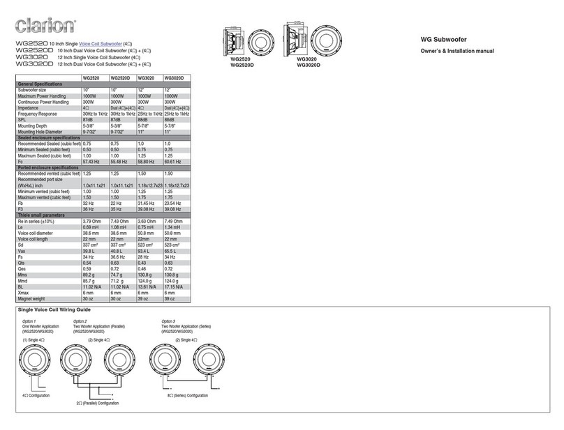
Clarion SRW8000 User manual

Clarion

Clarion SRW8000 User manual

Clarion SRV303 Instruction Manual

Clarion

Clarion SRV303 Instruction Manual

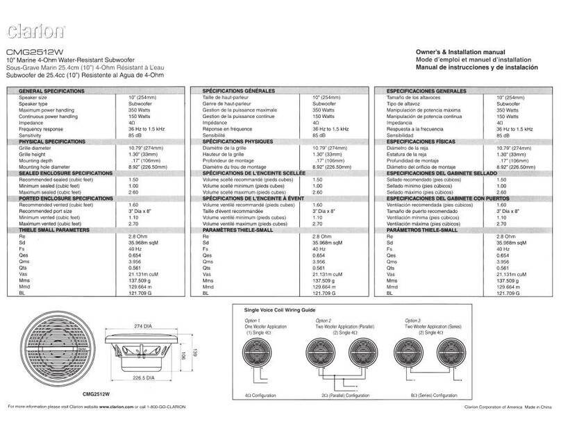
Clarion CMG2512W Quick start guide

Clarion

Clarion CMG2512W Quick start guide

Clarion PXW1241 User manual

Clarion

Clarion PXW1241 User manual

Clarion GRAND CHEROKEE PSWJPGC User manual

Clarion

Clarion GRAND CHEROKEE PSWJPGC User manual

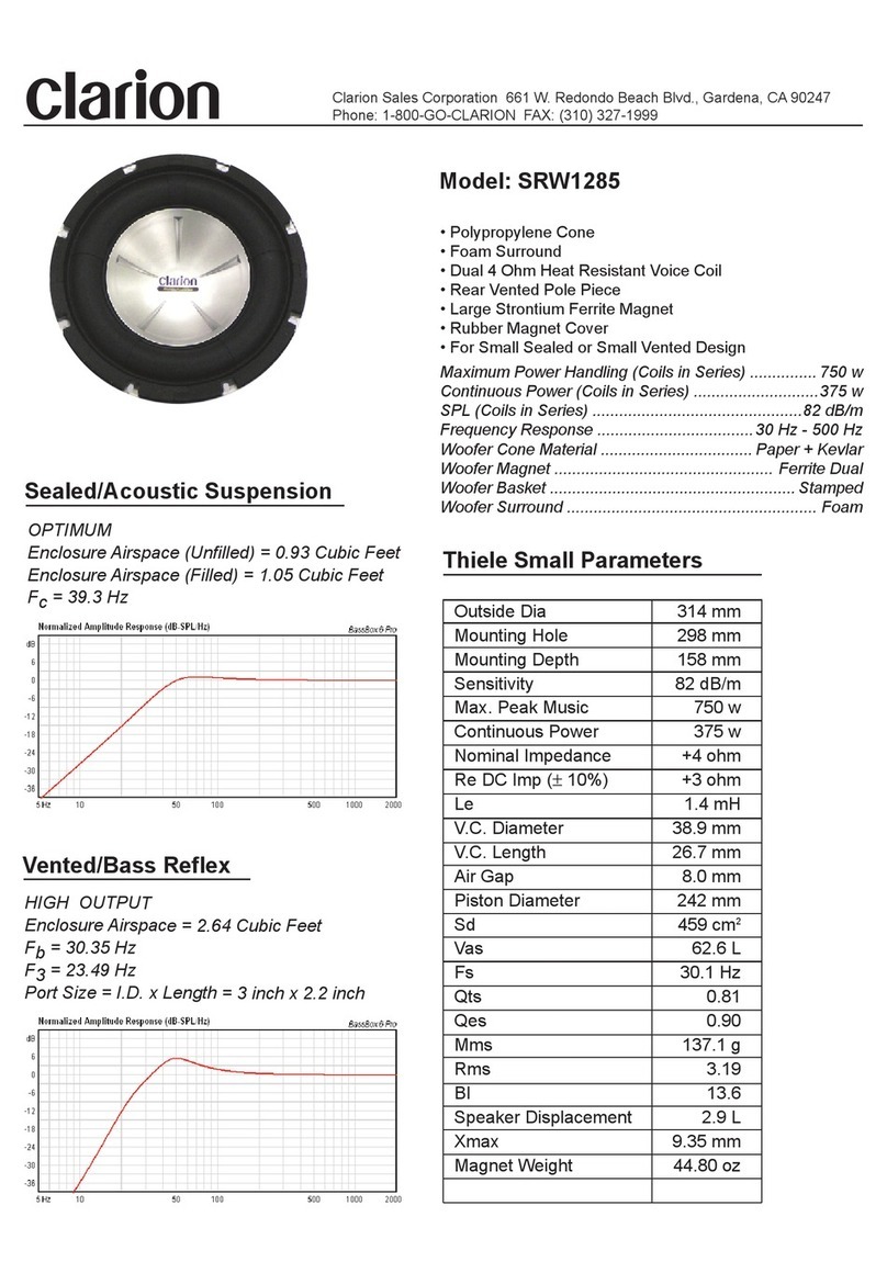
Clarion SRW1285 User manual

Clarion

Clarion SRW1285 User manual

Clarion SRV314 Instruction Manual

Clarion

Clarion SRV314 Instruction Manual

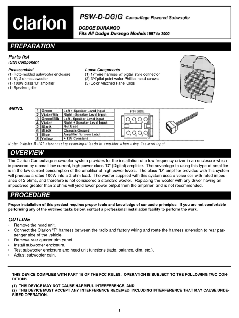
Clarion PSW-D-DGIG User manual

Clarion

Clarion PSW-D-DGIG User manual

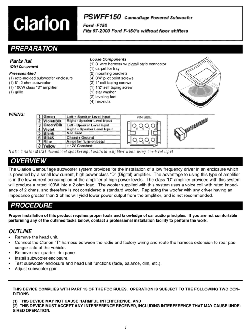
Clarion PSWFF150 User manual

Clarion

Clarion PSWFF150 User manual

Clarion SRV314 Instruction Manual

Clarion

Clarion SRV314 Instruction Manual

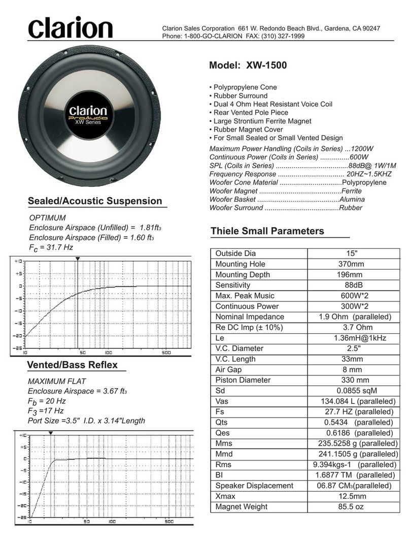
Clarion XW1500 User manual

Clarion

Clarion XW1500 User manual

Clarion PFW User manual

Clarion

Clarion PFW User manual

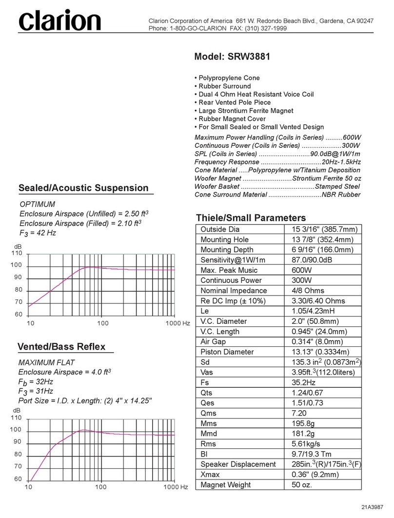
Clarion SRW3881 User manual

Clarion

Clarion SRW3881 User manual

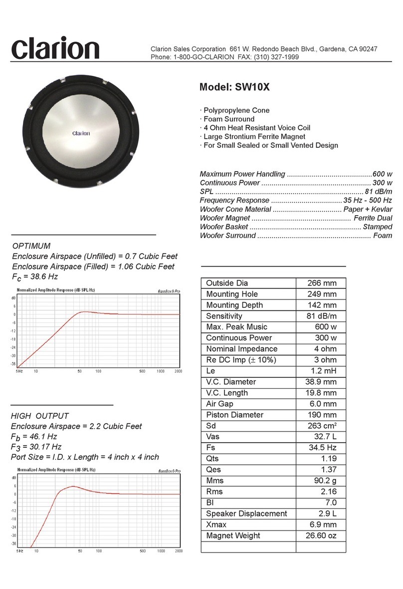
Clarion SW10X User manual

Clarion

Clarion SW10X User manual

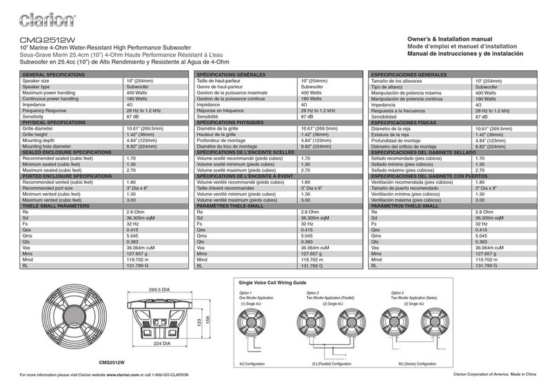
Clarion CMQ2512W Quick start guide

Clarion

Clarion CMQ2512W Quick start guide

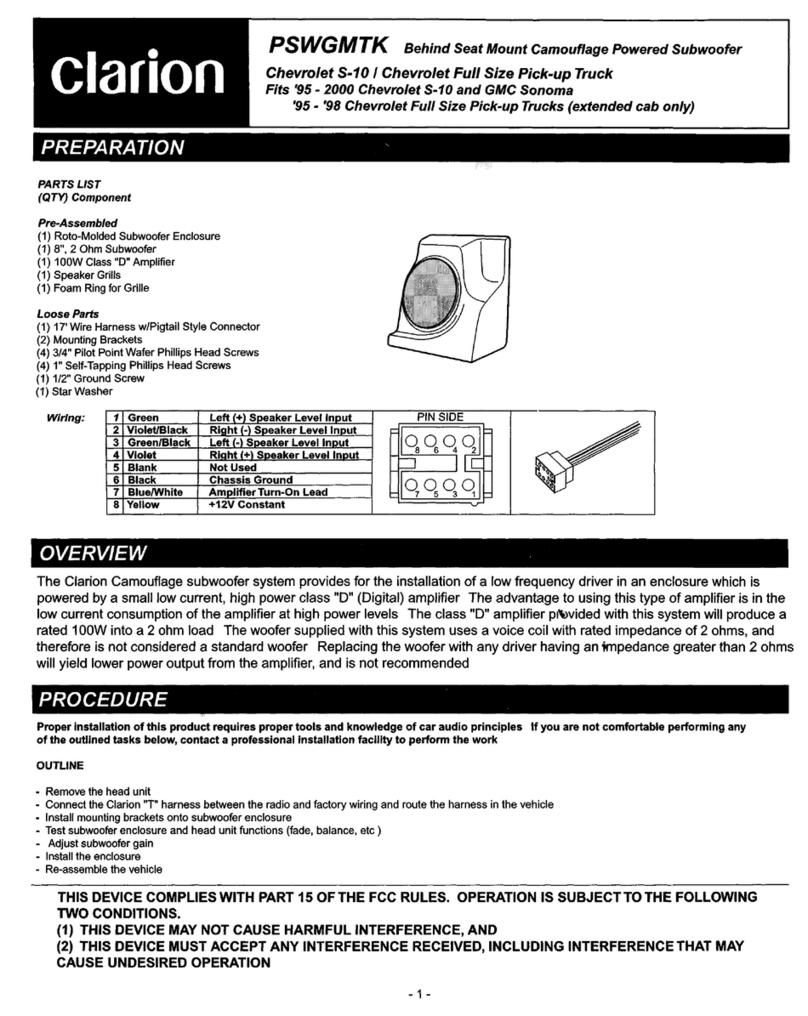
Clarion PSWGMTK User manual

Clarion

Clarion PSWGMTK User manual

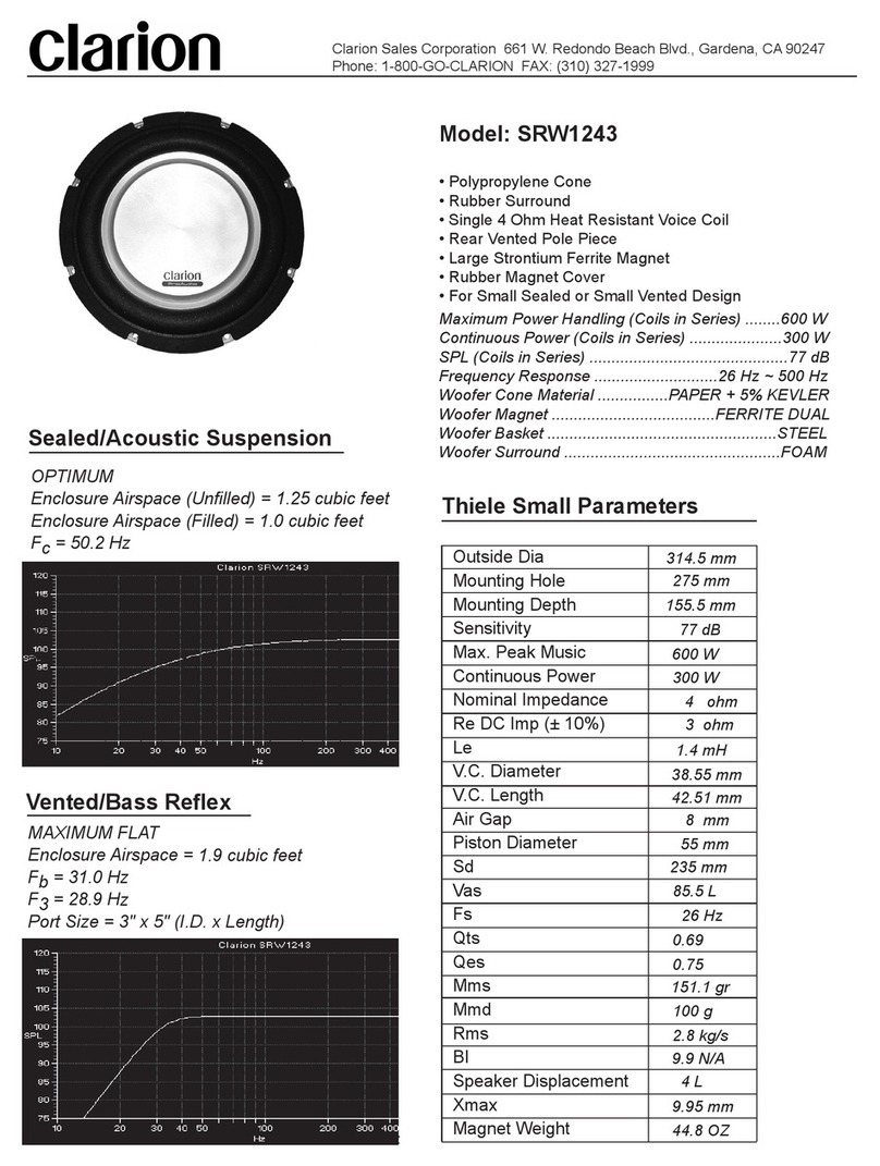
Clarion SRW1245 User manual

Clarion

Clarion SRW1245 User manual

Clarion CMQ2010W User manual

Clarion

Clarion CMQ2010W User manual

Clarion Full Digital Sound Z25W User manual

Clarion

Clarion Full Digital Sound Z25W User manual

Clarion SSW1201 User manual

Clarion

Clarion SSW1201 User manual

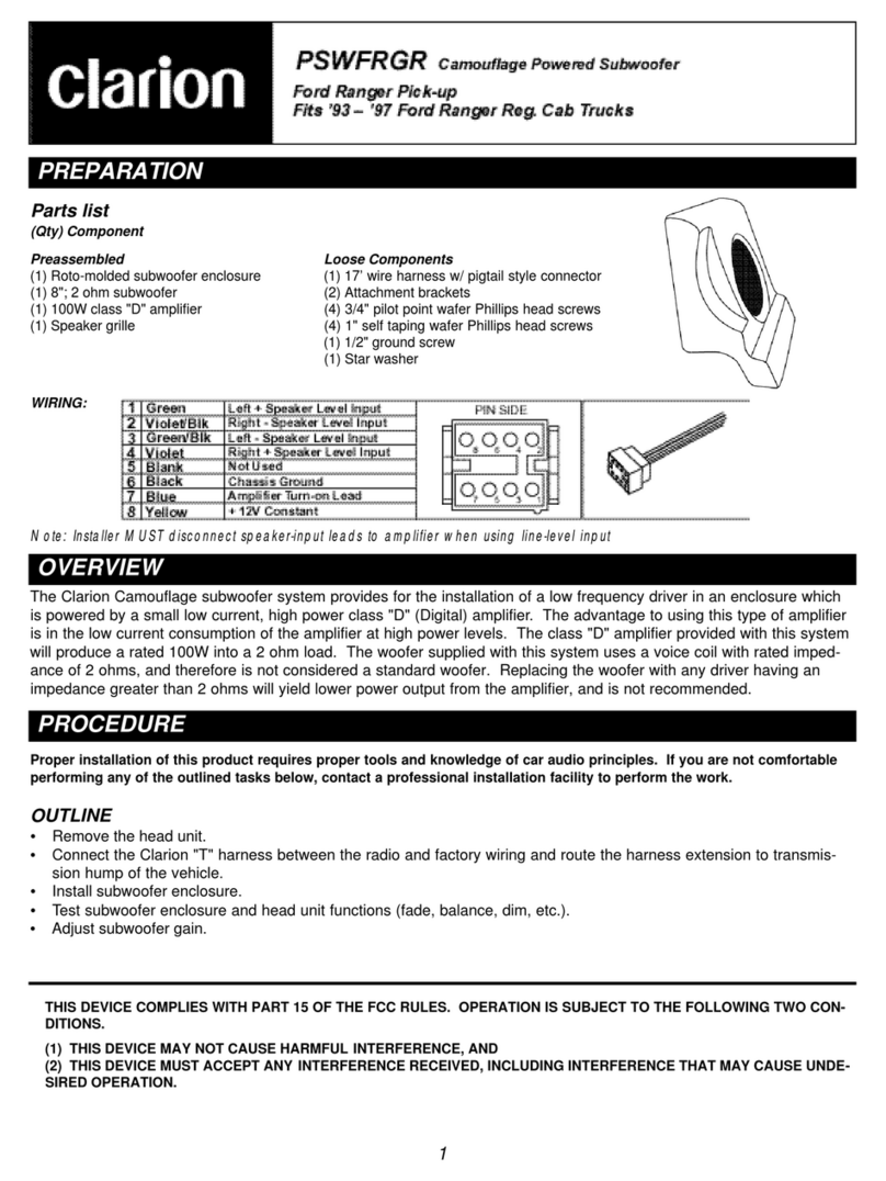
Clarion PSWFRGR User manual

Clarion

Clarion PSWFRGR User manual

Clarion WF2520 Service manual

Clarion

Clarion WF2520 Service manual

Clarion WG2520 Quick start guide

Clarion

Clarion WG2520 Quick start guide

Clarion PFW1051 User manual

Clarion

Clarion PFW1051 User manual

Popular Subwoofer manuals by other brands

Stealthbox SB-T-TACCAB/10W3v3 installation guide

Stealthbox

Stealthbox SB-T-TACCAB/10W3v3 installation guide

Energy Connoisseur ESW-M6 owner's manual

Energy

Energy Connoisseur ESW-M6 owner's manual

Martin Audio Line Array Subwoofer W8LS Specifications

Martin Audio

Martin Audio Line Array Subwoofer W8LS Specifications

Velodyne VRP-1000 Specifications

Velodyne

Velodyne VRP-1000 Specifications

AudioBahn ATB8ET operating instructions

AudioBahn

AudioBahn ATB8ET operating instructions

Sony XS-GS120L Specifications

Sony

Sony XS-GS120L Specifications

Aiwa XP-V311 Service manual

Aiwa

Aiwa XP-V311 Service manual

Infinity BETA SW-10 owner's guide

Infinity

Infinity BETA SW-10 owner's guide

Pioneer S-DV350SW Service manual

Pioneer

Pioneer S-DV350SW Service manual

Blaupunkt GTr 100 A Operating and installation instructions

Blaupunkt

Blaupunkt GTr 100 A Operating and installation instructions

KLH Windsor 10 user manual

KLH

KLH Windsor 10 user manual

Infinity 80.1w instructions

Infinity

Infinity 80.1w instructions

DB Drive Okur K2 10D4 Installation instructions & owner's manual

DB Drive

DB Drive Okur K2 10D4 Installation instructions & owner's manual

Boss Audio Systems Chaos CH10 user manual

Boss Audio Systems

Boss Audio Systems Chaos CH10 user manual

Pyle PLPPS110 manual

Pyle

Pyle PLPPS110 manual

Kenwood KFC-WPS1D instruction manual

Kenwood

Kenwood KFC-WPS1D instruction manual

Soundstream PWS-10 owner's manual

Soundstream

Soundstream PWS-10 owner's manual

Infinity Kappa Series perfect 12 VQ supplementary guide

Infinity

Infinity Kappa Series perfect 12 VQ supplementary guide

manuals.online logo
manuals.online logoBrands
  • About & Mission
  • Contact us
  • Privacy Policy
  • Terms and Conditions

Copyright 2025 Manuals.Online. All Rights Reserved.