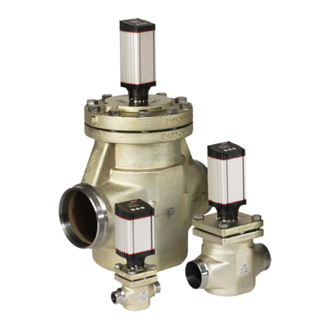
Clark Cooper EH40 User manual

941 Hamilton avenue
Roebling, nj 08554
www.ClarkCooper.com
Page 1of 7
Installation and Operation Manual
EH40, Version 2017.1
Last Updated: 6/26/2017
Installation:
The EH40-04, regardless of voltage, may be
mounted in any orientation (sideways, upside
down, etc.) and will still function per the catalog
specifications. AC powered EH40-08’s may also be
mounted in any orientation. However, DC powered
EH40-08’s must be mounted vertically with the coil
on top in order to open against the catalog
differential pressures.
Pipelines or tubing needs to be adequately
supported to prevent strains on the valve body
connections.
The ¼-18 NPT or ½-14 NPT valve body threads per ANSI/ASME B1.20.1 require a sealant, such as PTFE
tape, by design. Follow the sealant manufacturer installation instructions. Some general guidelines are:
Use only 2 to 3 wraps (max) of PTFE tape around the external thread.
Looking at the external thread, wrap the PTFE tape clockwise. When the threads are
turned together, this will eliminate friction trying to unravel the tape.
Start the tape at least one thread away from the end to eliminate any change of a
thread getting in the flow path.
Do not combine thread sealant and PTFE tape.
Do not back off a connection simply to adjust orientation. This may destroy the seal.
There is surprisingly no set specification that dictates exact torque values for taper threads. A
reputable fitting manufacturer goes as far as to make the statement below.

941 Hamilton avenue
Roebling, nj 08554
www.ClarkCooper.com
Page 2of 7
Due to our agreement with this statement, we err on the side of caution and do not publish
installation torque values for NPT threads. SAE J1926 fittings, on the other hand, are supplied
by various manufacturers who publish installation torques in catalogues. Please follow those
installation instructions for use in our 316 stainless steel valve bodies.
It is not recommended to use liquid sealant on the NPT connections. Often, the sealant fluid
leaks into the valve is gets deposited on critical areas such as the seat, the pilot orifice, and
other areas that inhibit optimal performance and quality sealing.
Make sure that connecting pipes or tubes are clean and free of particulates. Particulates and
debris are the most common reason for valves not sealing properly.
Install a filter upstream and close to the solenoid valve (see details in Filter section).
No lubrication is required. Most often, it is not necessary to lubrication internal components.
Occasionally, a very small amount of grease may be used to simply wet the piston and bonnet
tube o-rings for ease of assembly or low friction movement. However, the valve should function
well without it.
If the valve has been disassembled for service or cleaning, re-install the bonnet retainer with 23
ft*lbs of torque using a spanner wrench purchased from Clark Cooper.
Filters:
Foreign matter such as particulates, rust flakes, PTFE tape, pipe dope, etc., can jam moving parts
within a solenoid valve, clog the small orifices, or damage softer sealing surfaces. The result can
be a failure to open, close, and seal. A strainer or filter with 200 mesh (0.0029" gaps) or finer is
recommended for the EH40 Series products.
The strainer should be placed upstream (inlet side) and as close to the valve as possible. Be sure
to select a model that is safe for the inlet pressure. Size the filter so that the pressure drop
across it is acceptable for the flow rate.

941 Hamilton avenue
Roebling, nj 08554
www.ClarkCooper.com
Page 3of 7
Built in filters are now being offered.
Sealing:
Six different valve seat leakage classifications are defined by ANSI/FCI 91-2-2004. All valves
must pass a leakage test prior to the leaving the factory based on the requirements of this
specification.
This standard leakage for the EH40 product is Class 2. Class 5 is available.
Electrical:
Electrical wiring must conform to the nameplate rating. Wiring, conduit, and conduit
connections must comply with National and Local Electrical Codes. The standard solenoid
enclosure has a ½” NPT conduit connection. Standard lead wires supplied are 18” long, and are
wire gauge size 18 AWG minimum. The wire used to connect to the power source should be the
same or heavier gauge. Cables extending from ATEX approved coils are 3000mm [118”].
Custom leads lengths may be available upon request.

941 Hamilton avenue
Roebling, nj 08554
www.ClarkCooper.com
Page 4of 7
Unless noted otherwise, all solenoids are designed to operate at ±10% of the nominal voltage.
Check the valve nameplate for specific voltage and amperage requirements. If the ambient
and/or fluid temperature is elevated, it is suggested to keep that voltage no higher than nominal
to reduce to the risk of burnout (!).
Fuses or circuit breakers are recommended and should be sized according to the inrush
amperage and holding amperage requirements of the solenoid.
If the coil is oriented in an inconvenient direction, it may be re-oriented as described in the
SAFETY section of this manual. Either coil lead can be hot or neutral.
Standard AC and DC coil wiring:
Figure 1. Typical AC and DC coil wiring.
Figure 1 above shows the proper wiring for both AC and DC coils for the EH40 series valves. For
DC coils, one lead wire should be connected to the positive terminal and the other lead wire
should connect to the negative terminal. For AC coils, one lead wire should connect to the hot
terminal and the other lead wire should connect to the neutral terminal. These coils do not have
a ground wire. The coil has no polarity so either lead wire from the coil can be the positive lead
as both solenoid and valve performance will not be affected.
Optional DC Wiring With Flyback Diode:
Figure 2. DC coil wiring with flyback diode.

941 Hamilton avenue
Roebling, nj 08554
www.ClarkCooper.com
Page 5of 7
In some systems, it may be useful to install a flyback diode to protect the circuit. The flyback
diode prevents sparking between the contacts of the switch that controls power to the DC coil.
When the circuit is closed, current flows through the coil and a magnetic field builds inside of
the coil winding. Current does not flow through the diode as long as the breakdown voltage of
the diode is higher than the voltage across the coil. When the switch is opened, the magnetic
field inside of the coil starts to dissipate and in doing so, generates current in the coil and can
create a very large negative voltage spike. Because of the large potential, sparks can jump
between the contacts of the switch if there is no flyback diode. With the flyback diode, there is
still a closed circuit for the current to flow through even though the switch is open. The current
will flow through the loop between the diode and the coil until all of the energy is lost and will
not spark across the switch.
The UF4001-UF4007 series of diodes may be used as flyback diodes for circuit protection from
DC coils. These diodes will handle the low current that is created by the magnetic field after the
coil is turned off. Because they are fast acting, the decay time of the flyback current will be
relatively shorter compared to other diodes. The table below shows what specific diode should
be used for certain coil voltages.
The table of diodes is a suggestion ONLY. The entire circuit should be designed and analyzed by
a licensed Professional Electrician or an Electrical Engineer. The Clark Cooper Division of
Magnatrol Valve Corporation is not responsible for electrical system damage due to faulty wiring
or inadequate protections.
Coil Voltage
Flyback Diode
12V DC
UF4001
24V DC
UF4001
120V DC
UF4004
DIN Connector Option Pin-out:
Figure 3. DIN Type A male pinout.

941 Hamilton avenue
Roebling, nj 08554
www.ClarkCooper.com
Page 6of 7
Coils can come with an optional Type A male DIN Connector. The pinout can be seen above. The
coil has no polarity so the positive and negative terminals on the DIN connector are
interchangeable. The ground pin is not used in these coils.
Safety:
Depressurize a system before trying to remove the valve.
Do not pressurize the valve without the coil installed. While the valve is designed to not burst at
pressures approaching four times the rated maximum inlet pressure, the coil actually provides a
portion of that inherent strength.
If the wires from the coil need to be directed a certain way, loosen the nut on top of the coil
before trying to re-orient. Do not grab any portion of the bonnet tube with a wrench or plyers.
Doing so can damage the tube, loosen the retainer causing leakage, or damage an o-ring.
The surface temperature of some coils may be >200 degrees Fahrenheit (!) when held in the
energized state. Use caution when handling a coil that has just been in use.
Troubleshooting:
1. NEVER attempt to disassemble a valve that is under pressure. This may result is a serious
injury or death(!).
2. Some configurations of the EH40 require vertical mounting with the coil on top. See section
on installation.
3. The valve must be mounted in the correct ‘flow direction’ as indicated by the arrow on the
side of the valve body. An arrow points to the inlet on the EH40 Series products.
4. This valve will not act as a check valve. It only blocks flow in the direction of inlet to outlet.
5. Foreign matter such as particulates, PTFE tape, pipe dope, etc., can jam moving parts within
the valve or clog very small orifices. The result can be a failure to open and/or close
completely. See the section on filters/strainers in this manual.
6. The operating pressure must not exceed the pressure rating on the valve nameplate.

941 Hamilton avenue
Roebling, nj 08554
www.ClarkCooper.com
Page 7of 7
7. Verify that the power supplied to the solenoid matches the specification that is displayed on
the valve nameplate. Valves cannot be converted from DC to AC or AC to DC by simply
changing the coil. Contact Clark Cooper Sales for more information.
8. Check the coil leads for continuity. If there is no continuity, the circuit is open, most likely
due to burnout. A jammed plunger on an AC powered valve can cause coil burnout.
Replacing the coil may temporarily cure the symptom but not the actual cause.
9. This valve is designed and tested for use with gases, water, and fluids with viscosity similar
to water. Viscous fluids may slow or inhibit operation.
10. If chatter or buzzing is ever noticed, remove power and consult customer service. This could
indicate jammed components and could eventually burn out a coil or fatigue sealing
surfaces. Progressively increasing chatter may be an indicator of particulate build-up and
pitting of the plunger.
Solenoid Replacement:
1. Disconnect the solenoid from the power supply.
2. Remove the top solenoid nut and washer.
3. Remove the solenoid and replace with new one.
4. Replace washer and nut loosely.
5. Position the conduit connection as necessary and tighten the nut just until the wave washer is
flat.
6. Reconnect the power supply.
**Visit clarkcooper.com for product specific assembly videos.
This manual suits for next models
2
Table of contents
