9
Parts & Service: 020 8988 7400 / E-mail: Parts@clarkeinternational.com or Service@clarkeinternational.com
DC CURRENT MEASUREMENT
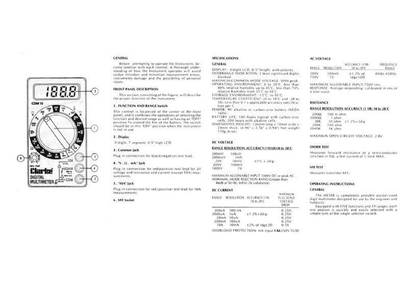
1. Plug the black probe into the COM jack. For current to be measured not
exceeding 200mA, plug the red probe into the “ mAVΩ” jack. For
current to be measured between 200mA and 10A, plug the red probe into
the 10A jack.
2. Set the rotary switch to the desired A range and connect the probe in
series with the load to be measured. The current value and the polarity
connected to the red probe will be shown on the display.
NOTE: If you do not know the measured voltage range in advance, set
the rotary switch to the maximum range, and then gradually turn
to smaller ranges until satisfactory resolution is found.
NOTE: If the display shows “1”, this indicates an over-range
measurement, and the switch should be set to a higher range.
NOTE: The symbol beside the probe indicates the maximum input
current is 200mA or 10A, depending on the inserted
jack.depending on the inserted jack. Excess current will blow the
fuse.
AC VOLTAGE MEASUREMENT
1. Plug the red probe into the “ mAVΩ” jack and the black probe into
the “COM” jack.
2. Turn the rotary switch to V~ and connect the probe to the power supply or
load to be measured.
NOTE: Refer to points above for direct current voltage measurement.
RESISTANCE MEASUREMENT
1. Plug the black probe into the COM jack and the red one into the
mAVΩjack.
2. Turn the rotary switch to the COM jack and connect the test probes to the
resistor being measured. Read the results on the display.
NOTE: If the resistor being measured is greater than the maximum value
of the selected range, the display will show “1”, requiring the
selection of a higher range. It normally takes a few seconds for
the reading to get stable when measuring a resistor larger than
1MΩ.
NOTE: In default of input, for instance, open circuit, the display shows
“1”.
NOTE: When measuring an online resistor, de-energize the circuit being
measured and discharge all capacitors.
