For support please visit
bulldogtracking.co.uk/support
Bulldog Security Products Ltd, Units 1-4 Stretton Road. Much Wenlock. Shropshire. TF13 6DH 7
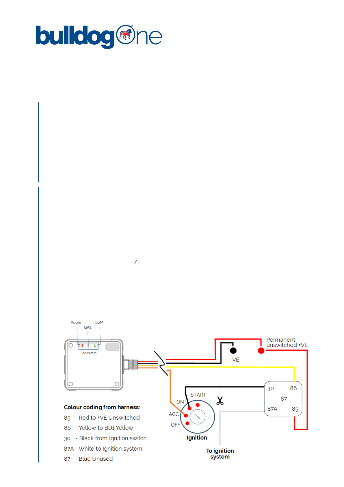
The BulldogOne and Immobiliser functionality is pre-congured to work with our tracking service and no
attempt should be made to alter any settings in the tracker that are not explicitly detailed within these
instructions.
Any attempt to change any other settings is in breach of the terms of our tracking service as are detail at
www.bulldogtracking.co.uk and could result in your BulldogOne tracker becoming permanently inoperable
or not operating in the manner that it is designed to work.
USE OF ANY ACCESSORIES NOT APPROVED AND SUPPLIED BY BULLDOG WILL VOID ANY PRODUCT WARRANTY.
BULLDOG SHALL IN NO EVENT BE LIABLE FOR ANY SPECIAL, INDIRECT, INCIDENTAL, CONSEQUENTIAL OR PUNITIVE DAMAGES OR
FOR LOSS, DAMAGE, OR EXPENSE, INCLUDING LOSS OF USE, PROFITS, REVENUE, OR GOODWILL, DIRECTLY OR INDIRECTLY ARISING
FROM PURCHASER’S USE OR INABILITY TO USE THE PRODUCT, OR FOR LOSS OR DESTRUCTION OF OTHER PROPERTY OR FROM ANY
OTHER CAUSE, EVEN IF BULLDOG HAS BEEN ADVISED OF THE POSSIBILITY OF SUCH DAMAGE. BULLDOG SHALL HAVE NO LIABILITY
FOR ANY DEATH, PERSONAL AND/OR BODILY INJURY AND/OR DAMAGE TO PROPERTY OR OTHER LOSS WHETHER DIRECT,
INDIRECT, INCIDENTAL CONSEQUENTIAL OR OTHERWISE, BASED ON A CLAIM THAT THE PRODUCT FAILED TO FUNCTION.
THE TRACKING SERVICE ASSOCIATED WITH THE BULLDOG TRACKER IS PROVIDED SUBJECT TO OUR TERMS AND CONDITIONS AT
WWW.BULLDOGTRACKING.CO.UK THE BULLDOGONE TRACKER CONTAINS NO USER SERVICEABLE PARTS AND ANY ATTEMPT TO
REMOVE THE COVER OR DISMANTLE WILL VOID ANY PRODUCT WARRANTY.
THESE INSTRUCTIONS MAY BE MODIFIED OR CHANGED WITHOUT NOTICE.
BD1/201805-11/GEN-IK1
Important
The BulldogOne tracking app, allows for the management and control of multiple vehicles using one log in.
Care should be taken when using the Engine Cut Oand Arm functions, as detailed in this manual, to ensure
that the correct vehicle is sent the command. Failure to follow these instructions, where you operate multiple
vehicles from one app log in, could result in vehicles not operating as expected i.e. the wrong vehicle has the
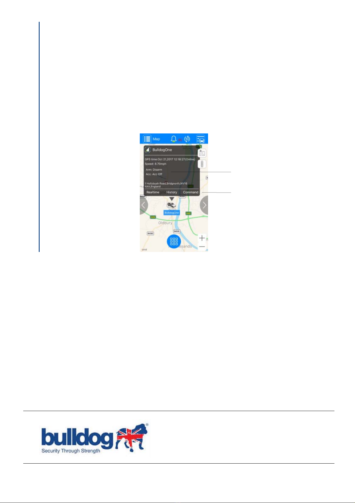
engine immobilised. To send a command to a tracker.
Tap Menu, Map. tap the Tracker Select icon and tap the name of the tracker you want to send a
command. (If there are multiple vehicles in the same location, zoom into the map) Tap the icon of the
tracker to bring up the status screen as shown in Fig 5.
Tap Command in the status window and the command screen will be displayed allowing you to select the
required command and this command will be sent only to the selected tracker.
14. MULTI-VEHICLE MANAGEMENT
Fig. 5
Status Window
Command function