manuals.online logo
Brands
  1. Home
  2. •
  3. Brands
  4. •
  5. BENDIX
  6. •
  7. Automobile Accessories
  8. •
  9. BENDIX Gen. 4 ABS ECU User manual

BENDIX Gen. 4 ABS ECU User manual

1
S-1509 ©2008 Bendix Commercial Vehicle Systems LLC 1/08 Printed in U.S.A. All Rights Reserved.
Installation
Instructions
Read and follow all standard safety guidelines, including
those found in the General Maintenance Precautions
section on page 2 of this document.
ThereplacementcontrollerisaGen.5™ABS ECU,whichdoes
not support J1922 engine communications, so, as mentioned
above, for installations which use J1922, please also follow
the Section “Retarder Relay Installation.” To determine if
the vehicle is using J1922, verify if pins 1 and 3 on the X1
connector are being used, or connect the vehicle to a PC
computerandusethe Bendix®ACom™Diagnostics program to
lookfor“Retarder Control” on theECUStatusor Configuration
screens. Bendix®ACom™Diagnostics is available as a free
download from the bendix website.
FIGURE 2 - WIRING DIAGRAM WHERE J1922
COMMUNICATION TO RETARDER IS REQUIRED
1
2
3
4
5
6
7
8
9
10
11
12
13
14
15
16
17
18
ECU
Power
Retarder
Relay
Engine ECM Retarder Pin
J1922
-
J1922
+
Ignition
Switch
17 Way Connector
5 A
Fuse
X1 Pin 7
X1 Pin 17
7
17
Reconfiguration
Afterinstallation,in all cases,useadiagnostic tool such asthe
Bendix®ACom™Diagnostics program, Nexiq Pro Link (using
theEaton cartridge), orthe blink codeswitch, to verifythat the
configuration of the ABS ECU is correct.
Remove the Controller Assembly
1. Locate the Gen 4™ECU on the vehicle.
2. Note if pins 1 and 3 of X1 are used (indicating retarder
control over J1922 was used). Where they are present,
remove and discard these wires.
3. Release all the connectors to the ECU assembly.
4. Remove the original mounting bolts from the controller.
Retain the bolts for re-installation.
Install Controller Assembly
1. Install the mounting bracket onto the replacement ECU,
using the nuts and bolts supplied in this kit.
2. Position the ECU/bracket assembly
at the original location
on the vehicle and attach
it using the original mounting
bolts.
Retarder Relay Installation
In cases where the Gen. 4™ABS ECU used the J1922 link
to control the retarder, the technician will need to hard-wire
a retarder relay for retarder control and remove the J1922
connection. Follow the wiring diagram in Figure 2 throughout
this procedure.
Required materials (not supplied): A 12V, 20/30 Amp,
automotive relay (single pole, double throw), a 5 Amp in-line
fuse, 18-gauge wire and terminals for the connector.
For many vehicles, the ECU replacement requires only
a changeout of the ECU and a reconfiguration step.
For vehicles where the original ECU used the J1922 link
to communicate with the engine retarder control, the
extra steps outlined in the “Retarder Relay Installation”
section will also need to be carried out.
Thiskitisintended toprovide thenecessary componentsto replace
aBendix
®
Gen.4
™
ABSECU (partnumber300126) with aBendix
®
Gen. 5
™
ABS ECU (part number 801753 or equivalent).
FIGURE 1 - KIT CONTENTS, VIEW OF ECU AND
CONNECTORS
X1
17Way
Connector
1
KIT CONTENTS
Item . . Description. . . . . . . . . . . Qty.
1. . . . Replacement ECU . . . . . . . . 1
(not shown). . Bracket. . . . . . . . . . . . . . 1
(not shown). . Bolts . . . . . . . . . . . . . . . 4
(not shown) . Nuts . . . . . . . . . . . . . . . 4
2
S-1509 ©2008 Bendix Commercial Vehicle Systems LLC 1/08 Printed in U.S.A. All Rights Reserved.
GENERAL MAINTENANCE PRECAUTIONS
WARNING! PLEASE READ AND FOLLOW THESE
INSTRUCTIONS TO AVOID PERSONAL INJURY OR
DEATH:
When working on or around a vehicle, the following general
precautions should be observed at all times.
1. Park the vehicle on a level surface, apply the parking
brakes, and always block the wheels. Always wear
safety glasses.
2. Stop the engine and remove ignition key when working
under or around the vehicle. When working in the
engine compartment, the engine should be shut
off and the ignition key should be removed. Where
circumstances require that the engine be in operation,
EXTREME CAUTION should be used to prevent
personal injury resulting from contact with moving,
rotating, leaking, heated or electrically charged
components.
3. Do not attempt to install, remove, disassemble or
assemble a component until you have read and
thoroughly understand the recommended procedures.
Use only the proper tools and observe all precautions
pertaining to use of those tools.
4. If the workis being performed onthe vehicle’s air brake
system, or anyauxiliary pressurized air systems,make
certain to drain the air pressure from all reservoirs
before beginning ANY work on the vehicle. If the
vehicle is equipped with anAD-IS®air dryer system or
a dryer reservoir module, be sure to drain the purge
reservoir.
5. Following the vehicle manufacturer’s recommended
procedures, deactivate the electrical system in a
manner that safely removes all electrical power from
the vehicle.
6. Never exceed manufacturer’s recommended
pressures.
7. Never connect or disconnect a hose or line containing
pressure; it may whip. Never remove a component or
plug unless you are certain all system pressure has
been depleted.
8. Use only genuine Bendix®replacement parts,
components and kits. Replacement hardware, tubing,
hose, fittings, etc. must be of equivalent size, type
and strength as original equipment and be designed
specifically for such applications and systems.
9. Components with stripped threads or damaged parts
should be replaced rather than repaired. Do not
attempt repairs requiring machining or welding unless
specifically stated and approved by the vehicle and
component manufacturer.
10. Prior to returning the vehicle to service, make certain
all components and systems are restored to their
proper operating condition.
11. For vehicles with Antilock Traction Control (ATC),
the ATC function must be disabled (ATC indicator
lamp should be ON) prior to performing any vehicle
maintenance where one or more wheels on a drive axle
are lifted off the ground and moving.
Follow Figure 2 throughout this procedure.
1. Crimp the terminal for the X1 connector to a wire which
will be inserted into pin location 17 of the X1 connector.
Connect the other end of the wire to the Relay coil.
2.
Connect a second wire to ignition power, by either splicing
the wire into the wire located in pin 7 of the X1 connector or
make a connection to the ignition switch, in either case be
sure the connection is protected by a 5 AMP fuse. Connect
the other end of the wire to the Relay coil.
3. ConnectathirdwiretotheengineECMmechanicalretarder
connection - see the vehicle manufacturer's manual as
needed for location. Connect the other end of the wire to
the Relay (typically the common/wiper connection).
4. Connecta fourth wireto the otherside of theNO (normally
open)connectiononthe relay and connecttheotherendof
the wire to ignition power, following the wiring diagram.
5. Install all other wire harness connectors, checking that
each connector snaps into the locked position.
OPERATIONAL TEST AND
RECONFIGURATION
Usea diagnostic toolsuchas the Bendix®ACom™Diagnostics
program, Nexiq Pro Link (using the Eaton cartridge), or blink
code switch (see Figure 3 below and Service Data Sheet
SD-13-4767)toreconfiguretheECUtoa4sensor,4modulator,
with retarder relay (if applicable) configuration.
Before returning the vehicle to service, use the diagnostic
tool to check the installation. Also, check for any diagnostic
trouble codes present and troubleshoot and/or make repairs
as necessary.
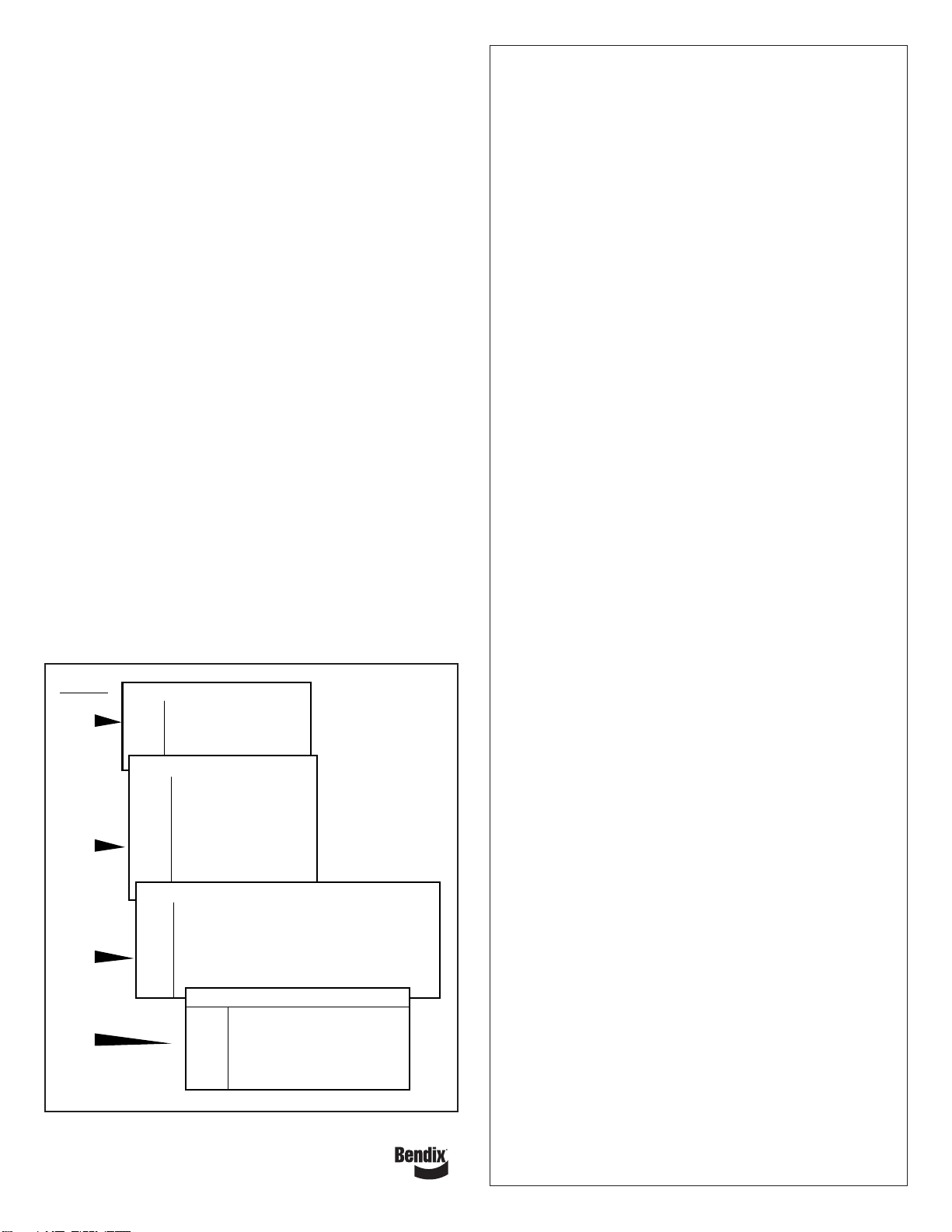
FIGURE 3 - READING ABS CONFIGURATION CODES
VOLTAGE CONFIGURATIONS
Flashes Description
1 12 Volt System
2 24 Volt System
ABS CONFIGURATIONS
Flashes Description
2 4 Sensors/4 Modulator Valves
3 4 Sensors/3 Modulator Valves
6 6 Sensors/4 Modulator Valves
8 6 Sensors/6 Modulator Valves
9 6 Sensors/5 Modulator Valves
– Select Low Steer
RETARDER CONFIGURATIONS/INTERAXLE
Flashes Engine Interface Retarder Relay Control Interaxle Lock Control
1 (5) NO NO NO (YES)
2 (6) YES NO NO (YES)
3 (7) YESNO NO (YES)
4 (8) YES YES NO (YES)
1st
2nd
3rd
4th
Blink Code
Sequence
1.5 Sec.
Pause
4.5 Sec.
Pause
1.5 Sec.
Pause
Flashes Engine Control Brake Control
2NO NO
3 N/A N/A
4 N/A N/A
5 YES YES
ATC CONFIGURATIONS

This manual suits for next models

3

Other BENDIX Automobile Accessories manuals

BENDIX BlindSpotter BW2860 Configuration guide

BENDIX

BENDIX BlindSpotter BW2860 Configuration guide

BENDIX TABS-6 TRAILER ABS MODULE Mounting instructions

BENDIX

BENDIX TABS-6 TRAILER ABS MODULE Mounting instructions

BENDIX ACTIVE STEERING SYSTEM User manual

BENDIX

BENDIX ACTIVE STEERING SYSTEM User manual

BENDIX VORAD VS-400 User manual

BENDIX

BENDIX VORAD VS-400 User manual

BENDIX Bendix Wingman ACB Mounting instructions

BENDIX

BENDIX Bendix Wingman ACB Mounting instructions

BENDIX Intellipark User manual

BENDIX

BENDIX Intellipark User manual

BENDIX AUTOVUE FLC-20 Mounting instructions

BENDIX

BENDIX AUTOVUE FLC-20 Mounting instructions

BENDIX SmarTire User manual

BENDIX

BENDIX SmarTire User manual

BENDIX TC-2 User manual

BENDIX

BENDIX TC-2 User manual

BENDIX SmarTire User manual

BENDIX

BENDIX SmarTire User manual

BENDIX Wingman FLR20 User manual

BENDIX

BENDIX Wingman FLR20 User manual

BENDIX ADB22X-V Mounting instructions

BENDIX

BENDIX ADB22X-V Mounting instructions

BENDIX Sheppard Mounting instructions

BENDIX

BENDIX Sheppard Mounting instructions

BENDIX Bendix Wingman Advanced User manual

BENDIX

BENDIX Bendix Wingman Advanced User manual

BENDIX VORAD VS-500 User manual

BENDIX

BENDIX VORAD VS-500 User manual

BENDIX TLV-9000 Mounting instructions

BENDIX

BENDIX TLV-9000 Mounting instructions

BENDIX VORAD VS-400 Installation and operation manual

BENDIX

BENDIX VORAD VS-400 Installation and operation manual

Popular Automobile Accessories manuals by other brands

Flash Cover MN024 installation manual

Flash Cover

Flash Cover MN024 installation manual

Mont Blanc CFK36 Fitting instructions

Mont Blanc

Mont Blanc CFK36 Fitting instructions

Thule EuroRide 941 manual

Thule

Thule EuroRide 941 manual

Firstech FTI-GMT3 quick start guide

Firstech

Firstech FTI-GMT3 quick start guide

Star Headlight & Lantern Star Half Phantom ULB14 Installation

Star Headlight & Lantern

Star Headlight & Lantern Star Half Phantom ULB14 Installation

aci ACCESS series Installation instructions and owner's manual

aci

aci ACCESS series Installation instructions and owner's manual

STO N SHO SNS 50 Installation procedures

STO N SHO

STO N SHO SNS 50 Installation procedures

STO N SHO SNS 68 Installation procedures

STO N SHO

STO N SHO SNS 68 Installation procedures

Satellic OBU user manual

Satellic

Satellic OBU user manual

Dynojet POWER VISION PV3-25-09 installation guide

Dynojet

Dynojet POWER VISION PV3-25-09 installation guide

Whispbar K374W Fitting Instructions for Basic Carrier

Whispbar

Whispbar K374W Fitting Instructions for Basic Carrier

Nokia CK-7W user guide

Nokia

Nokia CK-7W user guide

Cruz Evo Rack Pro P20-126 Assembly instructions

Cruz

Cruz Evo Rack Pro P20-126 Assembly instructions

enua Wallmount installation guide

enua

enua Wallmount installation guide

Safe Fleet Prime Design VCC TC11B manual

Safe Fleet

Safe Fleet Prime Design VCC TC11B manual

TAUBENREUTHER 16 - 590 Fitting instructions

TAUBENREUTHER

TAUBENREUTHER 16 - 590 Fitting instructions

Directed Directechs DS3 installation guide

Directed

Directed Directechs DS3 installation guide

NORAUTO 2396725 manual

NORAUTO

NORAUTO 2396725 manual

manuals.online logo
manuals.online logoBrands
  • About & Mission
  • Contact us
  • Privacy Policy
  • Terms and Conditions

Copyright 2025 Manuals.Online. All Rights Reserved.