CLASSIC LIFT CL4500 Manual
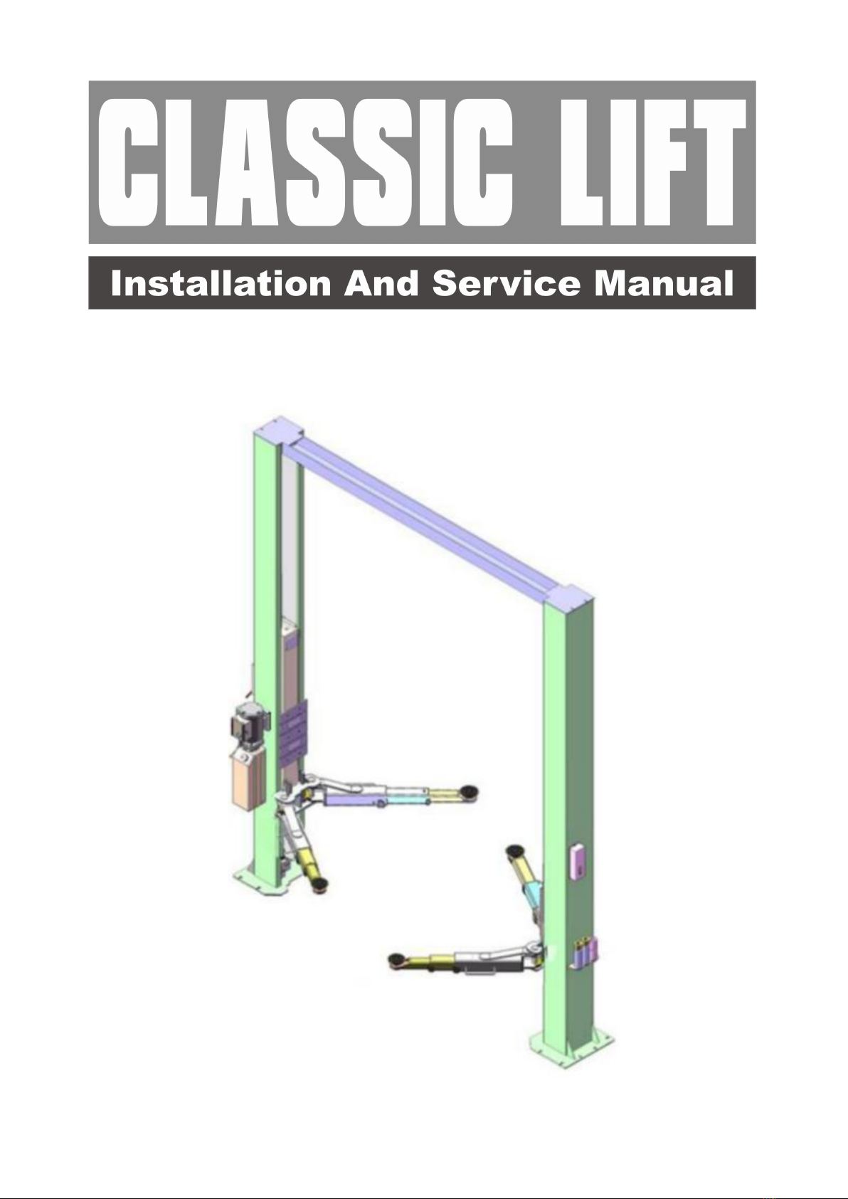
TWO-POST LIFT
Model:CL4500

CONTENTS
Product Features and Specifications ..............................................1
Installation Requirement .............................................................5
Steps of Installation ...................................................................7
Exploded View ...........................................................................22
Test Run ...................................................................................33
Operation Instruction .................................................................35
Maintenance .............................................................................36
Trouble Shooting .......................................................................37
LIFT DISPOSAL ...............................................................................37
1
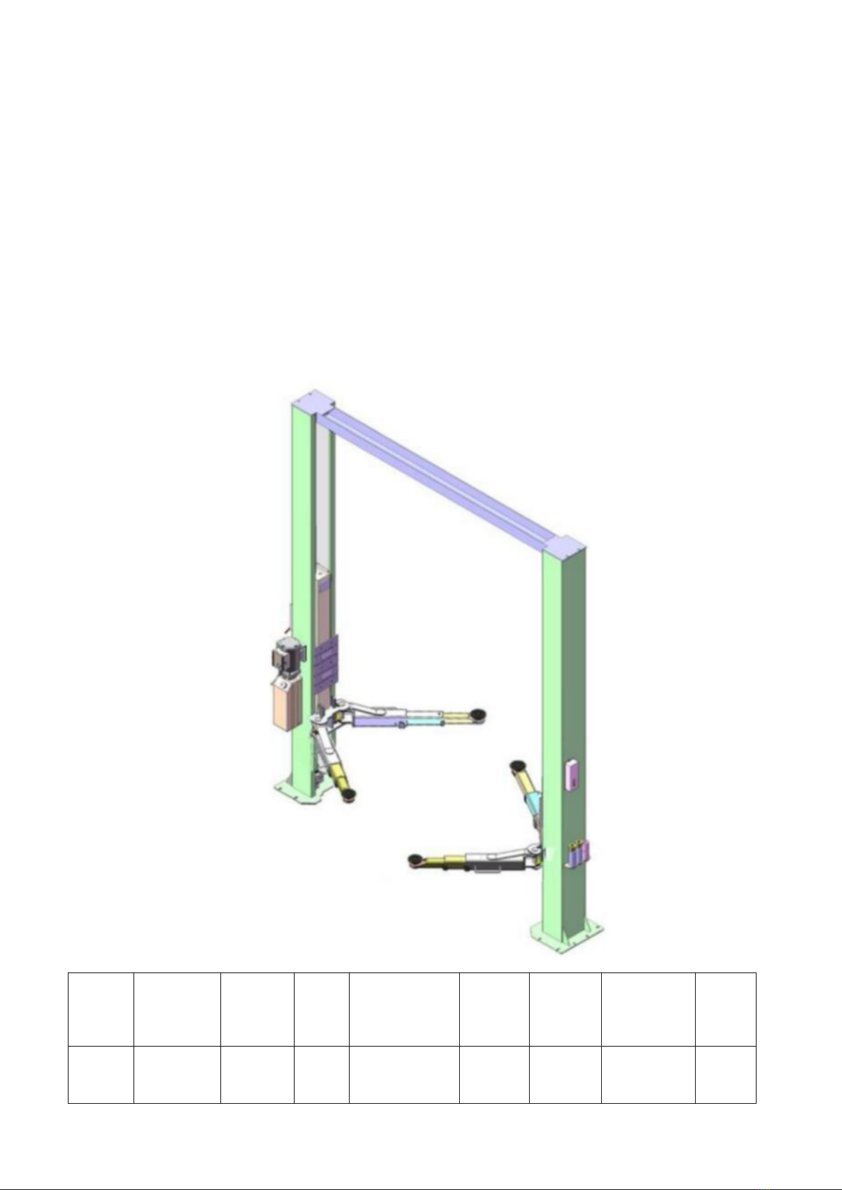
I. PRODUCT FEATURES AND SPECIFICATIONS
CLEARFLOOR DIRECT-DRIVED MODEL FEATURES
MODEL CL4500(See Fig.1)
· Direct-driving design, minimize the lift wear parts and breakdown ratio.
· Dual hydraulic cylinders, designed and made on high standard, high quality seals.
· Self-lubricating UHMW Polyethylene sliders and bronze bush.
· Single-point safety release, and dual safety design.
· Clear-floor design, provide unobstructed floor space.
· Overhead safety shut-off device.
· With 4 three stages arms, make lifts easily find the lift point of the car.
· Stackable adapters 1.5”, 2.5”, 5” as standard.
MODEL CL4500SPECIFICATIONS
Model
Style
Lifting
Capacity
Lifting
Time
Lifting Height
Overall
Height
Overall
Width
Minimum
Pad Height
Motor
CL4500
Clear-floor
Direct-drive
4500KG
60s
1940-2169mm
3854mm
3516mm
90-319mm
3.0HP
Fig. 1
2
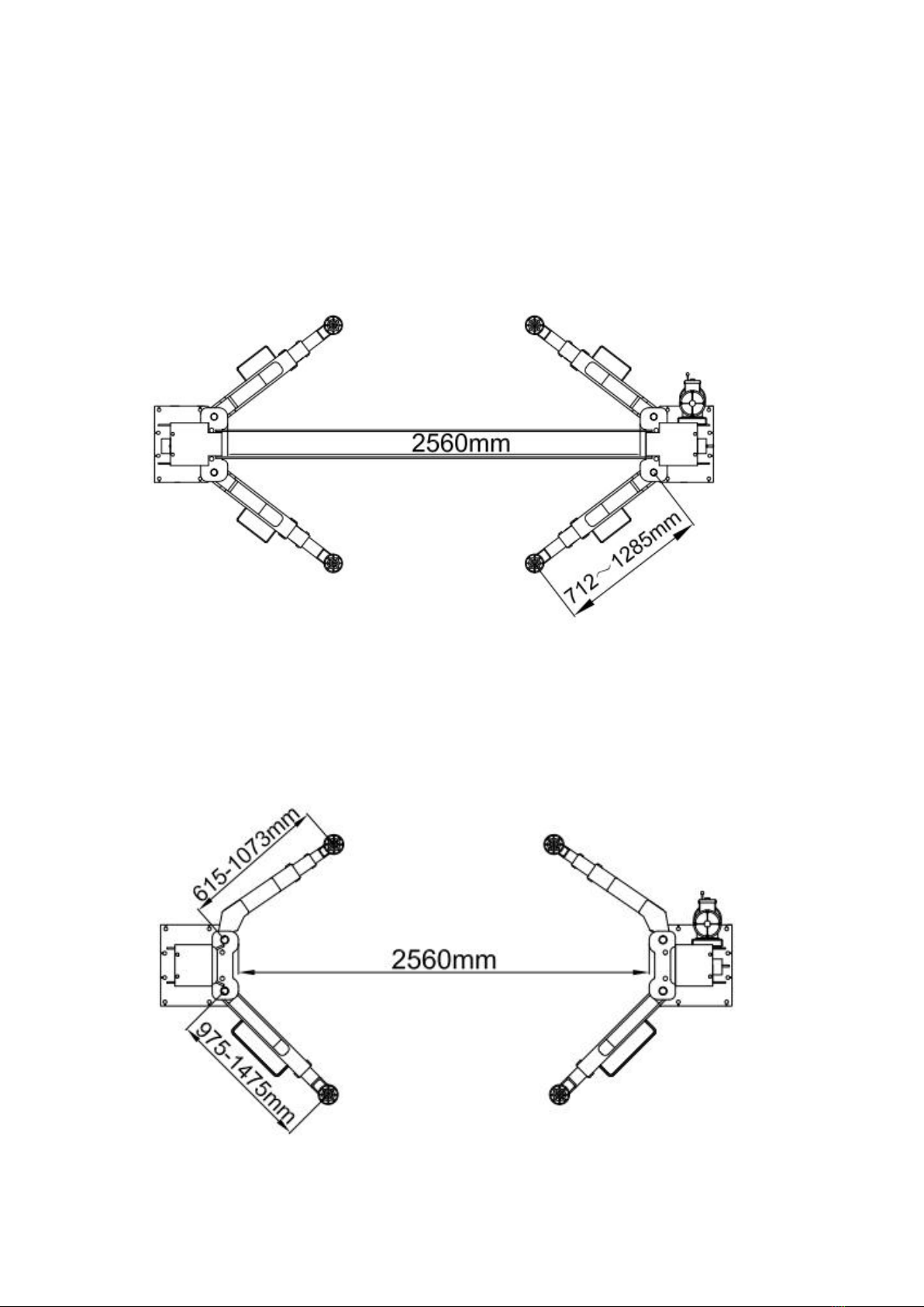
Arm Swings View
Fig. 3
For Model 210C
Fig. 4
For Model 210SAC
3
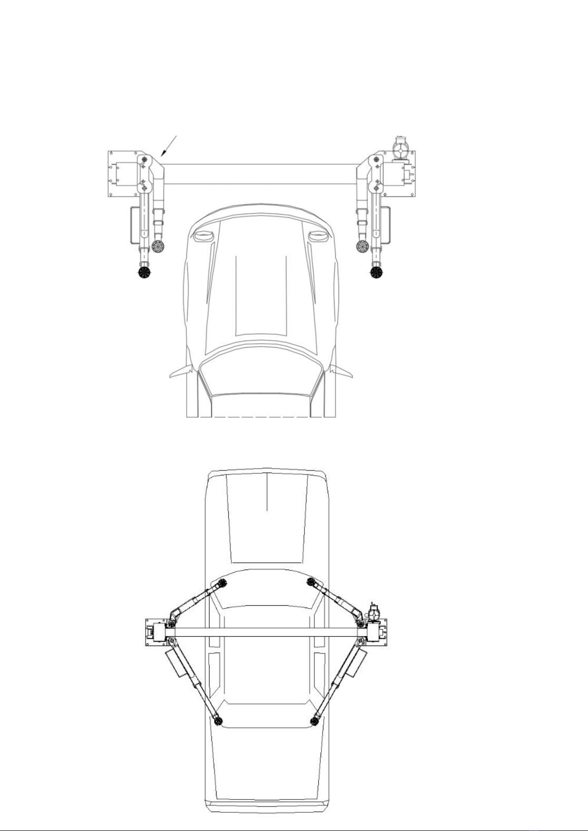
Swing and extending the arms to the lifting point of vehicle
Attention! Please make sure to place the arms in correct
position before car drive in!
Fig. 5
4
II. INSTALLATION REQUIREMENT
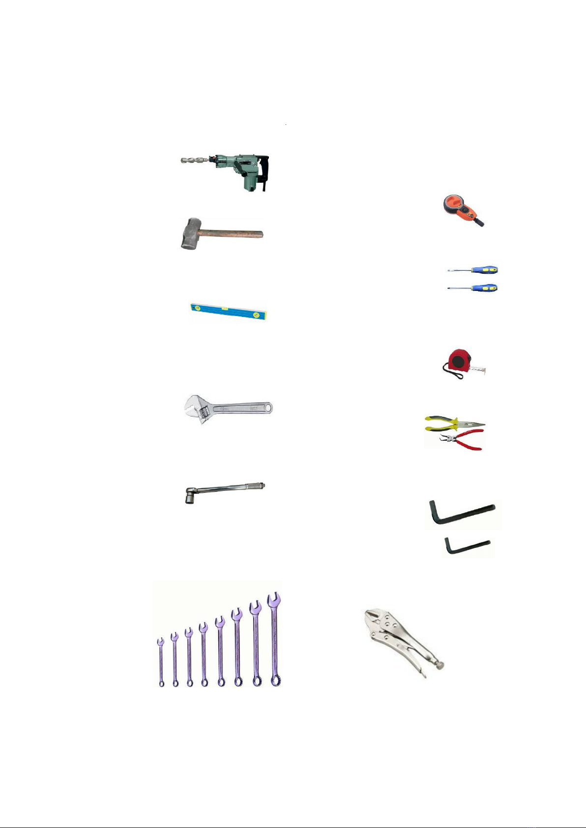
A. TOOLS REQUIRED
Rotary Hammer Drill (Φ19)
Hammer
Level Bar
English Spanner (12")
Ratchet Spanner With Socket (28#)
Wrench set
(10#, 13#, 14#, 15#, 17#, 19#, 24#,27#)
Carpenter’s Chalk
Screw Sets
Tape Measure (7.5m)
Pliers
Socket Head Wrench (3#, 6#)
Lock Wrench
Fig. 7
Fig. 6

5
B. Equipment storage and installation requirements.
The equipment should be stored or installed in a shady, normal temperature,
ventilated and dry place.
C.The equipment should be unload and transfer by forklift.
D. SPECIFICATIONS OF CONCRETE (See Fig. 9)
Specifications of concrete must be adhered to the specification as following.
Failure to do so may result in lift and/or vehicle falling.
1. Concrete must be thickness 100mm minimum and without reinforcing steel bars,
and must be dried completely before the installation.
2. Concrete must be in good condition and must be of test strength 3,000psi
(210kg/cm²) minimum.
3. Floors must be level without cracks.
E. POWER SUPPLY
The electrical source must be 2.2KW minimum. The source cable size must be
2.5mm² and in good condition of contacting with floor.
Fig. 9
Concrete intensive must be
3,000psi(210kg/cm²) minimum
67
Fig.8
100
6
III. STEPS OF INSTALLATION
A. Location of Installation
Check and insure the installation location (concrete, layout, space size etc.) is
suitable for lift installation.
B. Use a carpenter’s chalk line to establish installation layout of base plate (See Fig.
10).
C. Check the parts before assembly
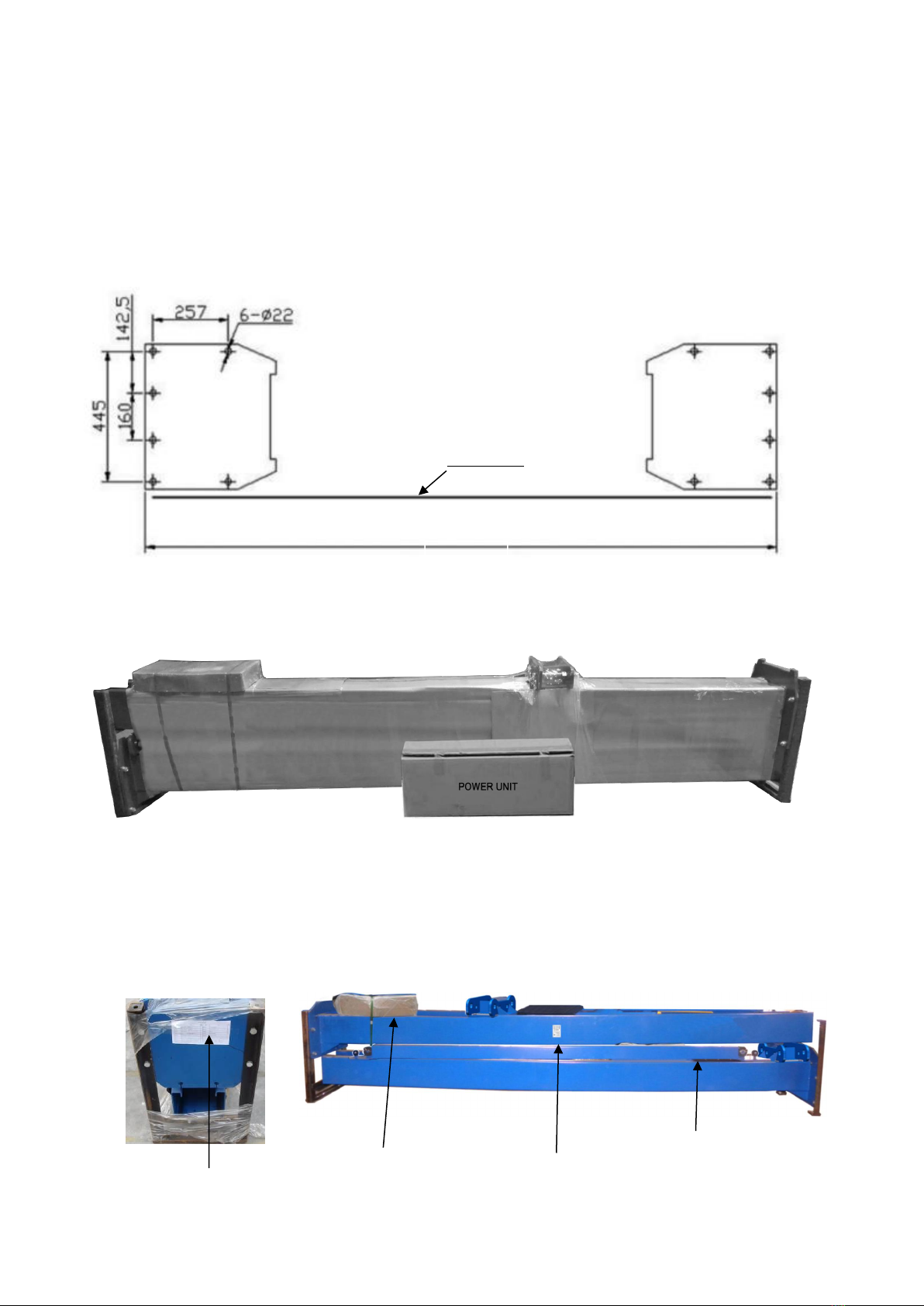
1.Packaged lift and hydraulic power unit (see Fig. 11)
2. Move the lift aside with a fork lift or hoist, and open the outer packing carefully ,
take off the parts from upper and inside the column, take out the parts box,check
the parts according to the shipment parts list (See Fig. 12).
Fig. 10
Fig. 11
Shipment Parts
list
Serial number
Top beam
Fig. 12
Chalk Line
Parts box.
3516mm

7
3. Loose the screws of the upper package stand, take off the upper column and remove
the package stand.
4. Move aside the parts and check the parts according to the shipment parts list
4.1 For Model 210C, (See Fig. 13, 14).
4.2 For Model 210SAC (See Fig. 15, 16).
37
Fig. 13
Parts in the shipment parts list
Fig. 14
Parts in the parts box (37)
37
Fig. 15
Parts in the shipment parts list
Fig. 16
Parts in the parts box (37)

8
5.Open the bag of parts and check the parts of the parts bag according to parts bag
list (See Fig. 17).
D. Position power side column
Lay down two columns on the installation site parallel, position the power side
column according to the actual installation site. Usually, it is suggested to install
power side column on the front-right side from which vehicles are driven to the lift
(See Fig. 18).
Fig. 17
Offside column
Power-side column
Car-in direction
Fig. 18
9
E. Lay down aside the columns with cables and oil hoses installed, face the
open way of each columns. (Fig.19)
F. Position columns
Place the columns on the installation layout of base plate. Install the anchor bolts.
Do not tighten the anchor bolts (See Fig.20).
Fig. 19
Overall width:3516mm
Notch is relatively
Anchor Bolt
Width between
columns: 2850mm
Fig. 20
Cleaning
Bolting
Drilling
90mm
Note: Minimum embedment of
anchors is 90mm.

10
G. Mounting the top beam by lifting equipment,and attention should be paid
to distinguish the direction when installing the top beam. Fig.21
H. Check the vertical of the columns with level bar, and adjusting with the shims if the
columns are not vertical. Tighten the anchor bolts (See Fig.22).
Tighten anchor bolts
Adjusting with
the shims
Fig. 22
Note: Torque of Anchors
is 150N.m
Measure the
vertical of column
from front and
side by a lever bar
or not.
Fig. 21
34
Power-side
Column
11
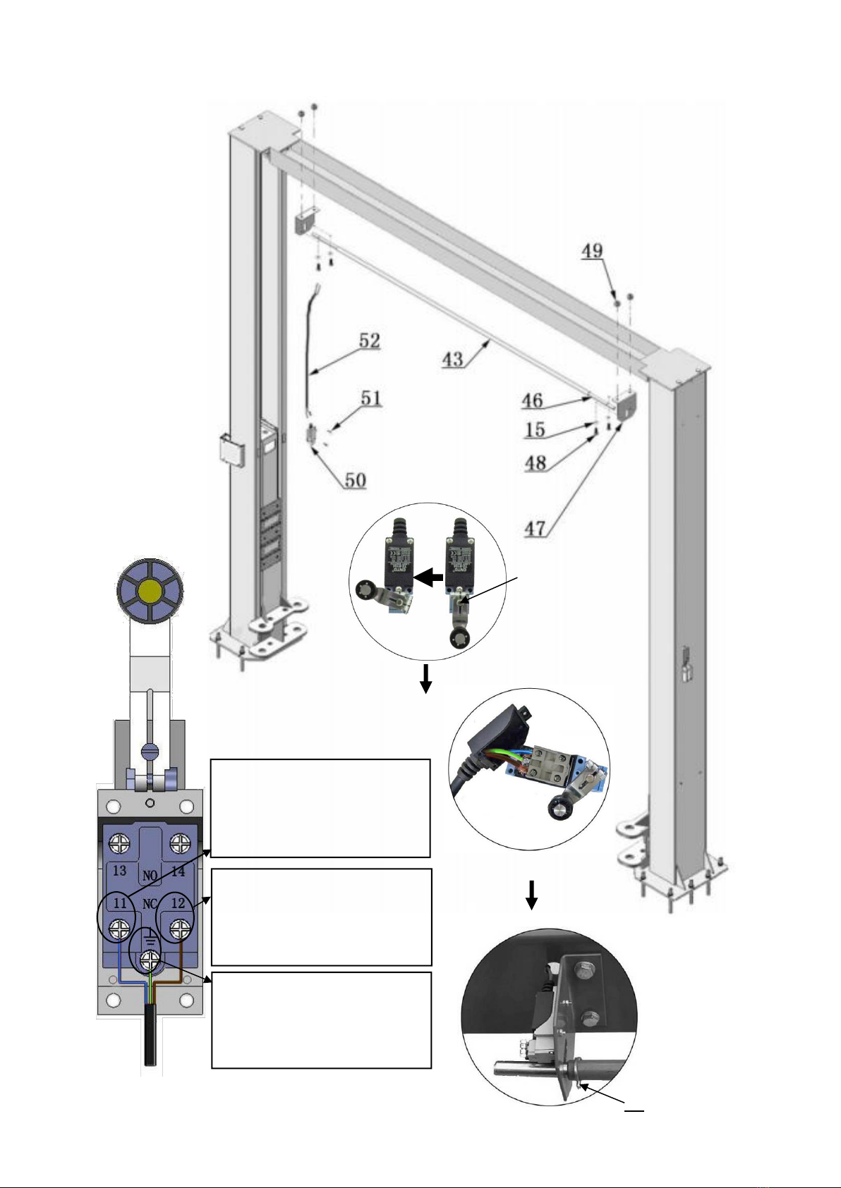
I. Install the limit switch control bar and limit switch (See Fig. 23).
NC: Normal contact
Fig. 23
Use 3# Socket
Head Wrench to
loosen the Screw
of drive rod for
adjustment
Limit switch is connected
with cable
Connect the blue wire to
terminal #11 on limit switch
and terminal A1 on AC
contactor of power unit.
Connect the brown wire to
terminal #12 on limit switch
and terminal #4 on button of
power unit
Connect the yellow and green
wire to earth wire terminal on
limit switch and earth wire
terminal of power unit
44

12
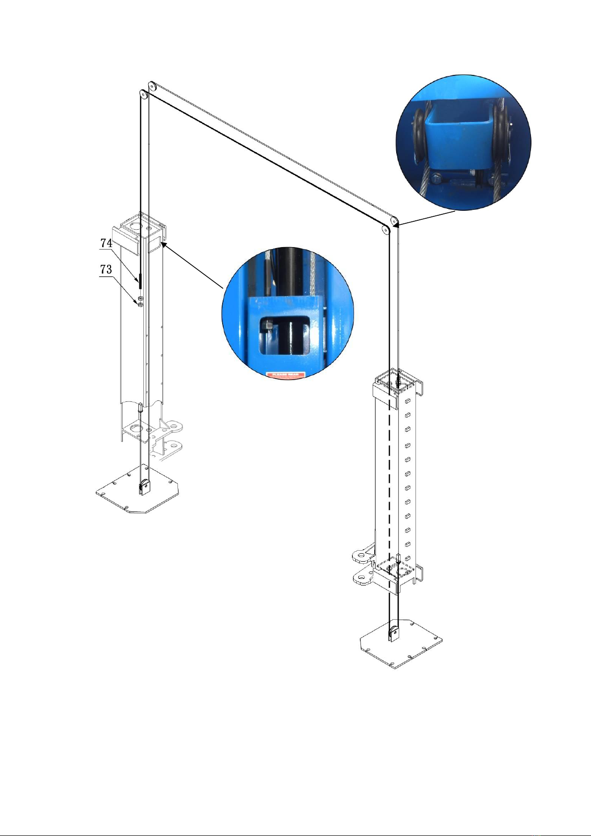
J. Install safety cable (See Fig. 24).
Cable through the bottom of the carriage
Cables pass through the
top plate of the carriages
Fig. 24
74
1. Pass one end of the
cable through the bottom
of the carriage and clamp
it on the slot
2. Pass the other end of
the cable up from the
bottom of the other lifting
carriage
20
74
After
installation
66
13
K. Install cables (See Fig. 25).
Fig. 25
14
L. Assembly oil hose.
1. For model CL4500 (See Fig. 26).
Fig. 26

15
M. Install power unit and oil hoses (See Fig. 27)
Pay attention to lock the hose joint and power to prevent oil leakage
The hose goes
through the clamp
After installing the fitting of
the power unit, tighten the
nut with 19#Wrench
Fig. 27

16
N. Install safety cable (See Fig. 28).
Pass through safety cable
View A
View B
Fig. 28
17
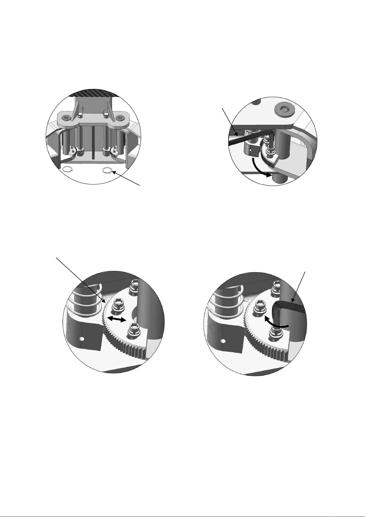
O. Install lifting arms and adjust the arm locks
1. Install the lifting arms (See Fig. 29).
2. Lowering the carriages to the lowest position, then use the 8#wrench to loosen the
nut of arm lock (See Fig. 30).
3. Adjust the arm lock as direction of arrow (See Fig. 31)
4. Adjust the moon gear and arm lock to make it to be meshed, then tighten the nut of
arm lock (See Fig. 32).
P. Tighten all the hydraulic fittings, and fill the reservoir with hydraulic oil.
Note: In consideration of Hydraulic Power Unit’s durability and keep the
equipment running in the perfect condition, please use Hydraulic Oil 46#.
Fig. 29
Fig. 30
Fig. 31
Fig. 32
Lock the nuts after the moon gear
and arm lock are engaged well
Lock the nut
Use the 8#wrench to
loosen the nut
Adjust the moon gear
Snap Ring

18
Q. Install electrical system
Connect the power source on the data plate of power unit.
Note: 1. For safety of operators, the power wiring must contact the floor well.
2. Pay attention to the direction of rotations when using three phase motors.
Single phase motor (See Fig. 33).
1. Connecting the two power supply lines (Active Land Neutral Wire N) to terminals of AC
contactor marked L1, L2 respectively.
2. Connecting the two motor wires to terminals of AC contactor marked T1, T2.
3. Connecting A2 to L2 of AC contactor.
4. Connecting the Limit Switch: Removing the wire of connecting terminal 4# on
control button and terminal A1 on AC contactor firstly (See Fig. 34), then
connecting wire 12# (brown color) of the limit switch with terminal 4# of the
control button and connecting wire 11# (blue color) with terminal A1 on AC
contactor respectively. Connecting the earth wire (green and yellow color) of the
limit switch with earth wire terminal on power unit. (See Fig. 35).
5. Connecting terminal 3# on control button with terminal L1 of AC contactor.
Switch Button
Limit Switch
AC contactor
Limit Switch
Switch Button
Power Supply
AC Contactor
Fig. 33
Table of contents
Other CLASSIC LIFT Lifting System manuals


Popular Lifting System manuals by other brands

ATD Tools
ATD Tools ATD2P11BS Installation & operation manual

ATH-Heinl
ATH-Heinl ATH Comfort Lift 2.35 user manual

Vestil
Vestil EHLTG owner's manual

HOMCOM
HOMCOM 713-087 Assembly & instruction manual

pewag
pewag levo hook LH Series Original operating manual

Southern States
Southern States EV installation instructions

Harmar Mobility
Harmar Mobility AL815CC Installation & owner's manual

Sinoboom
Sinoboom TB18E Plus Maintenance manual

R&M
R&M STAGEMAKER SM1 Technical guide

Schmalz
Schmalz VacuMaster Multi Series operating manual

Tommy Gate
Tommy Gate Railgate 1600 Series quick start guide

ato form
ato form VITA-LIFT user guide


