CLASSIC LIFT BP4 Manual

Two-Post Lift
Model:BP4
Original

CONTENTS
Product features and specifications...................................................2
Installation requirement .................................................................4
Steps of installation........................................................................6
Exploded view……………....................................................................17
Test run…………...............................................................................25
Operation Instruction ……................................................................26
Maintenance…...............................................................................27
Trouble shooting…………………………………………………………………….…………………28
Scarping of equipment...................................................................28

1
I. PRODUCT FEATURES AND SPECIFICATIONS
FLOORPLATE CHAIN-DRIVE MODEL BP4 FEATURES (See Fig. 1)
· Compact Floor-plate design, provides unobstructed floor space.
· Dual hydraulic cylinders, designed and made on high standards, high quality seals.
· Self- lubricating UHMW Polyethylene sliders and bronze bush
· Single-point safety release, and dual safety design
· 4pcs of 3-stages arms with stackable rubber pads.
MODEL BP4 SPECIFICATIONS
Model
Lifting
Capacity
Lifting Height
Lifting
Time
Overall
Height
Overall
Width
Minimum
Pad Height
Motor
BP4
4000kg
1815-1917mm
45S
2850mm
3390mm
90-192mm
3.0HP
Fig. 1

2
Arm Swings View
Fig. 2
2554mm

3
II. INSTALLATION REQUIREMENT
A. TOOLS REQUIRED
Rotary Hammer Drill (Φ19)
Hammer
Level Bar
English Spanner (12")
Ratchet Spanner With Socket (28#)
Wrench Set
Carpenter’s Chalk
Screw Sets
Tape Measure (7.5m)
Pliers
Socket Head Wrench (6#)
Lock Wrench
(10#, 13#, 14#, 15#, 17#, 19#, 24#, 27#)
Fig. 3

4
B. Equipment storage and installation requirements.
The equipment should be stored or installed in a shady, normal temperature, ventilated
and dry place.
C. The equipment should be unload and transfer by forklift.
D.SPECIFICATIONS OF CONCRETE (See Fig. 5)
Specifications of concrete must be adhered to the specification as following.
Failure to do so may result in lift and/or vehicle falling.
1. Concrete must be thickness 100mm minimum and without reinforcing steel bars,
and must be dried completely before lift installation.
2. Concrete must be in good condition and must be of test strength 210kg/cm2
(3,000psi) minimum.
3. Floors must be level and no cracks.
E. POWER SUPPLY
The electrical source must be 3HP minimum. The source cable size must be 2.5mm²
minimum and in good condition of contacting with floor.
Fig. 5
Concrete intensity must be
3000psi minimum
70
Fig.4
100
5
III. STEPS OF INSTALLATION
A. Location of installation
Check and insure the installation location (concrete, layout, space size etc.) is
suitable for lift installation.
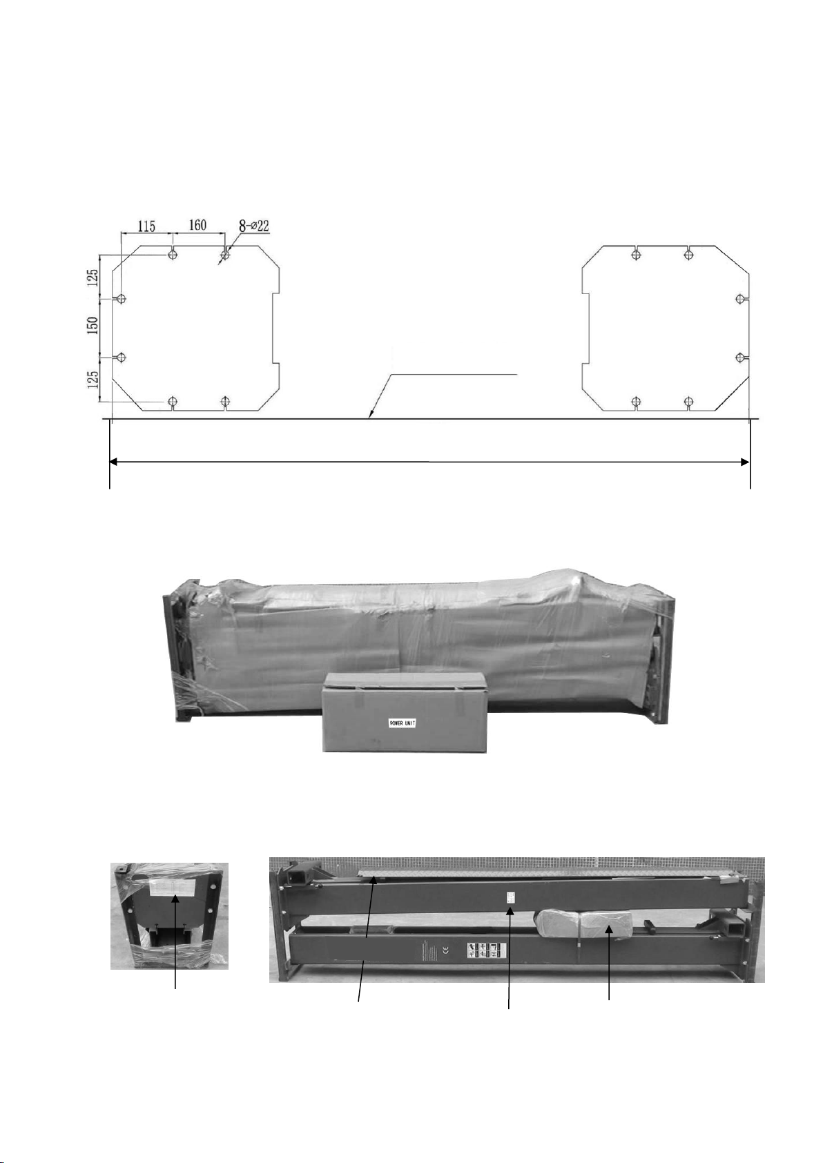
B. Use a carpenter’s chalk line to establish installation layout of baseplate (See Fig. 5).
C. Check the parts before assembly
1.Packaged lift and Hydraulic Power Unit (See Fig. 7)
2. Move aside the lift with fork lift or hoist, and open the outer packing carefully, take
off the parts from upper and inside the column, take out the parts box,check the
parts according to the shipment parts list (See Fig. 8).
Fig. 6
Shipment Part
Fig. 7
Fig. 8
Chalk line
3390m
m
Floor cover
Serial Name Plate
Parts Box
6
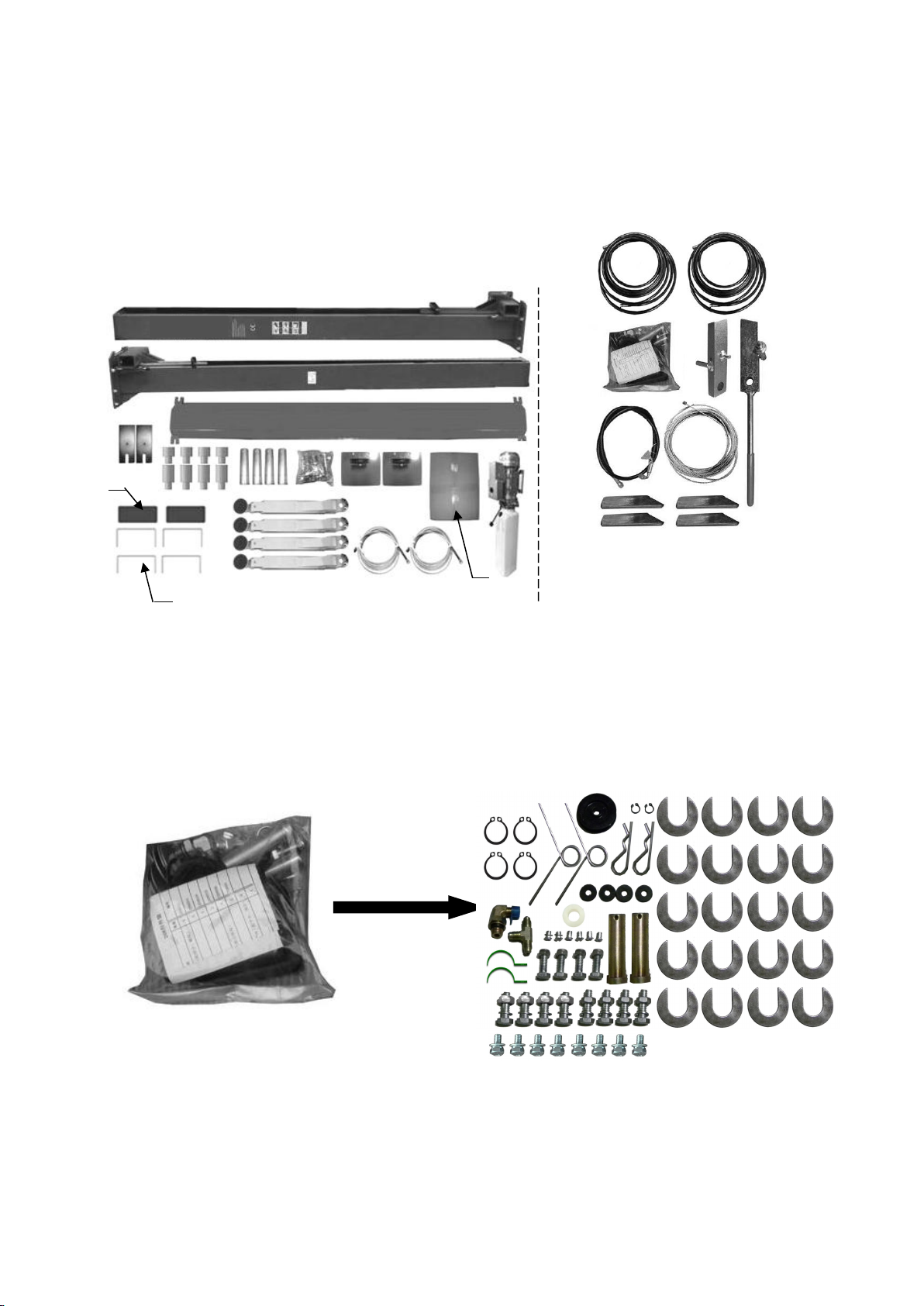
3. Loose the screws of the upper package stand, take off the upper column and remove
the package stand.
4. Move aside the parts and check the parts according to the shipment parts list (See
Fig. 9,Fig. 10).
5. Open the carton of parts and check the parts in the parts bag according to parts bag
list (See Fig. 11).
Fig. 11
Fig. 10 Parts in the parts box (71)
Fig. 9 Parts in the shipment parts list
42
43
71

7
Vehicle drive in Direction
Powerside column
Offside column
Assemble to plate using M10*35 hex
bolt with nut and washer
D. Position powerside column
Lay down two columns on the installation site parallelly, position the powerside
column according to the actual installation site. Usually, it is suggested to install
powerside column on the front-right side from which vehicles are driven to the lift.
(See Fig. 12)
E. Position columns (See Fig. 13)
Check the columns plumbness with level bar, and adjusting with the shims if the
columns are not vertical.
Fig. 12
2780 mm
Check the columns plumbness
with level bar from front and
side
3390mm
Fig. 13
A
B
8
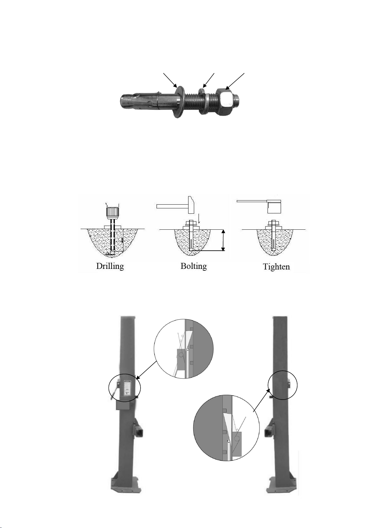
F. Fix anchor bolts
1. Prepare anchor bolts (See Fig. 14).
2. Using the prescribed rotary hammer drill, and drill all the anchor holes and install the
anchor bolts. Then tighten the anchor bolts (See Fig. 15).
Note: Torque of Anchors is 150N.m .Minimum embedment of Anchors is 90mm.
G. Lift the carriages up by hand and make them be locked at the same level
(See Fig. 16).
Lock washer
Washer
Nut
90mm
Fig.14
Fig.15
Fig. 16

9
H. Install cables (See Fig. 17)
Lift the carriages installation hole higher than chain pulley (for easy installation).
And make the both carriages be locked at the same level. Then pass cable through
the top pulley, and to be screwed to the upper steel plate of carriages with two cable
nuts.
Fig. 17
Pass cable through the top pulley, and to be
screwed to the upper steel plate of carriages with
two cable nuts.
59
60
10
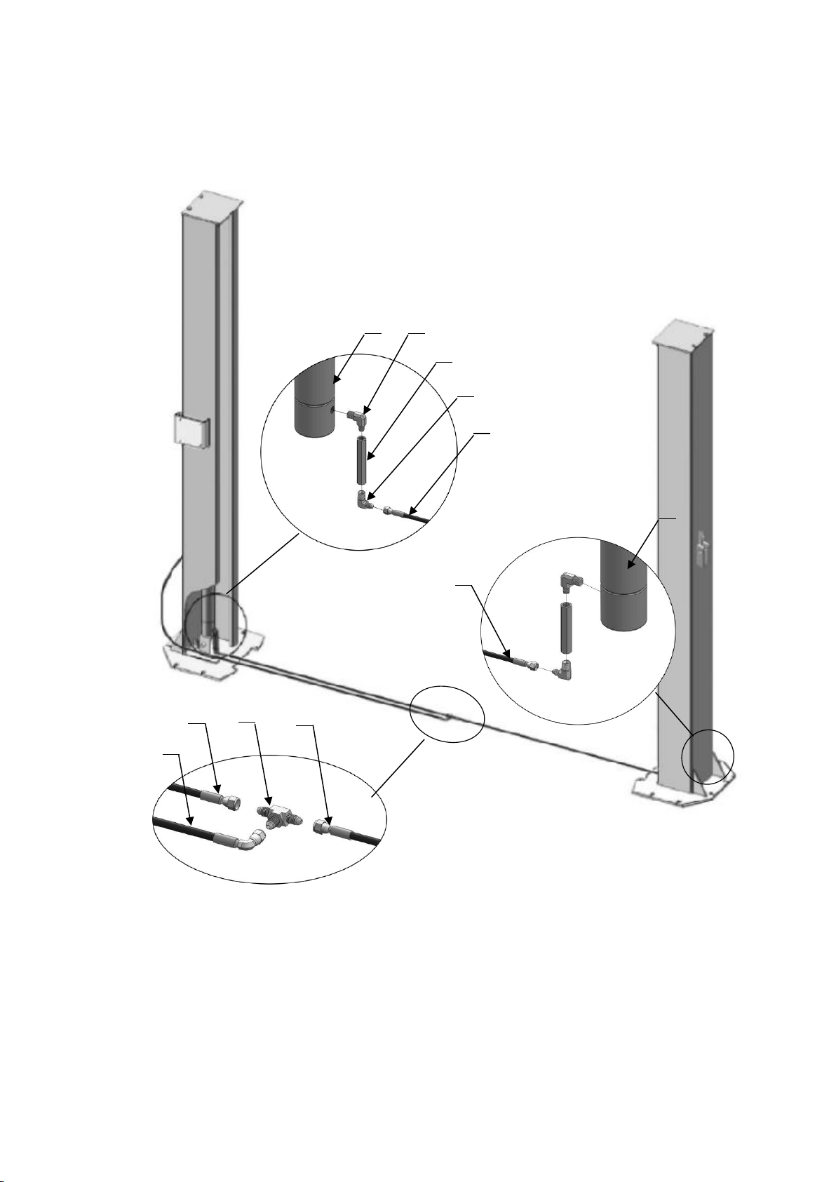
I. Assembly oil hose assy. (See Fig. 18)
Fig. 18
64
66
65
64
62
63
64
24
64
24
61
11
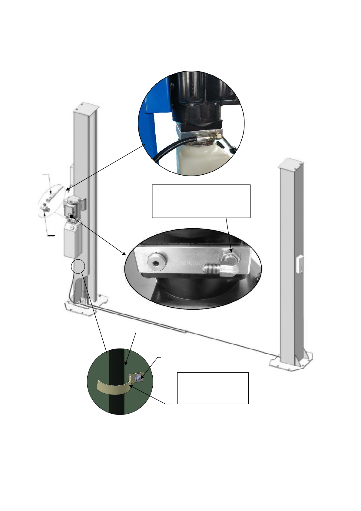
J. Install hydraulic power unit and oil hose (See Fig. 19)
Please tighten the fitting of the oil hose and power unit to avoid leaking. Fix the oil
hose of power unit with retainer.
Tighten all the hydraulic fittings, and fill the reservoir with hydraulic oil.
Fig. 19
Tighten the Nut with a 19#
Wrench after installing the
fitting of Power unit
68
66
Tighten the oil hose
of power unit with
retainer
5
66
67

12
K. Install safety cable (See Fig. 20)
NOTE: 1. Assemble safety cable from offside safety assy.
2. Pay attention to the connecting direction of safety cable.
Fig. 20
52
Connecting
direction of
safety cable
View A
View B
2
69
52
13
Protective Rubber Sets
Floor cover
L. Assemble floor cover and protective rubber sets (See Fig. 21).
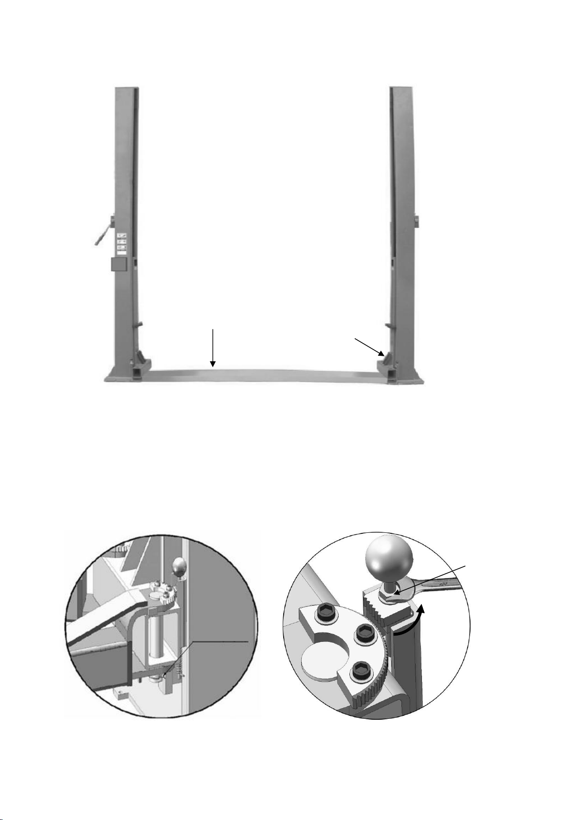
M. Install lifting arms and adjust the arm locks
1. Install the lifting arms (See Fig. 22)
2. Lowing the carriages down to the lowest position, then use the 17# wrench to
loosen the nut (See Fig. 23)
Fig. 22
Fig. 23
Snap Ring
Fig. 21
Loosen the nut

14
3. Adjust the arm lock as arrow direction (See Fig. 24).
4. Adjust moon gear and arm lock to make it to be meshed, then tighten the nut of
arm lock (See Fig. 25).
N. Tighten all the hydraulic fittings, and fill the reservoir with hydraulic oil.
Note: In consideration of Hydraulic Power Unit’s durability and keep the equipment running in
the perfect condition, please use Hydraulic Oil 46#.
O. Install electrical system
Connect the power source on the data plate of power unit.
Note: 1. For the safety of operators, the power wiring must contact the earth well.
2. Pay attention to the direction of rotations when using three phase motors.
Single phase motor
1. Circuit diagram (See Fig. 26)
Fig. 25
Fig. 24
Adjust the arm lock
Moon gear
Tighten the nut
Fig. 26

15
2. Connection step (See Fig. 27)
Connecting the two power supply wires (active wire Land neutral wire N) to terminals
of AC contactor marked L1, L3 respectively. Earth wire( yellow and green wire) is
connected with the earth wire terminal of the motor
Three phase motor
1. Circuit diagram (See Fig. 28)
Fig. 28
Power supply wires
Fig. 27

16
2. Connection step (See Fig. 29)
The power supply wires L1, L2, L3 are connected with terminals of AC contactor
marked L1, L2, L3 respectively.Earth wire( yellow and green wire) is connected with
the earth wire terminal of the motor.
Fig. 29
Power supply wires
Wire of motor

17
IV. EXPLODED VIEW
Model BP4
Fig. 30
Drive In

18
PARTS LIST
Item
Part#
Description
Qty.
Note
1
11201001C
Powerside column
1
2
10209011
Plastic Pulley
1
3
10209010
Snap Ring
2
4
10209008
Safety Cover
2
5
10209009
Cup Head Bolt
10
6
10206023A
Hex Nut
2
7
10206006
Washer
2
8
10209003
Hex Bolt
4
9
11206002
Safety Pin
2
10
10209007
Safety Spring
2
11
11209013
Powerside Safety Lock
1
12
10209012
Hair Pin
8
13
81513001/
81513002
Manual Power Unit
1
14
10209004
Rubber Ring
4
15
10209005
Self locking nut
8
16
10201002
Hex Bolt
12
17
10209034
Lock Washer
12
18
10209033
Washer
12
19
11201003
Floor Cover
1
20
10206046
Self-tapping Screw
4
21
10206045
Protective Rubber
2
22
10201010
Chain Connector
4
23
10201009A
Chain
2
24
11201008B
Hydraulic Cylinder
2
25
11201704
Chain Pulley Sea Assy.
2
26
11201011B
Powerside Carriage
1
27
10206044
Slider Block
16
28
11201038
Carriage Plastic Cover
2
29
10209020
Plastic Ball
4
30
10209021
Hex Nut
8
31
10209022
Washer
10
32
10209023A
Arm Lock
4
33
11201041
Limit Ring
4
34
11209024
Arm Lock Bar
4
35
10209025
Hair Pin
4
36
10209026
Spring
4
37
10209027
Protective Rubber Set
4
38
10201043A
Lifting Arm assy.
4
39
11201015B
Offside Carriage
1
40
10520023
Snap Ring
4
Table of contents
Other CLASSIC LIFT Lifting System manuals


Popular Lifting System manuals by other brands

twin busch
twin busch TW M-02 Installation, operation and maintanance

Inter-fab
Inter-fab Portable i-Lift instruction manual

Sinoboom
Sinoboom GTJZ0408SE parts manual

Tuxedo
Tuxedo JMC9KAC-TUX Installation & operation manual

Nussbaum
Nussbaum JUMBO HF 7000 Owners and installation manual

Sumner
Sumner Roust-a-Bout R Series Operator's manual

Oshkosh Corporation
Oshkosh Corporation JLG 830P Operation and safety manual

EZTRUNK
EZTRUNK 1900 0072 Assembly manual

Maxon
Maxon Tuk-A-Way GPT Series installation manual

Corghi
Corghi BL 600 Operator's manual

Challenger Lifts
Challenger Lifts CL4P9S Installation, operation & maintenance manual

nifty
nifty HR17 SP50 HYBRID SERIES Operating/safety instructions


