CLASSIC LIFT CL6800C Manual
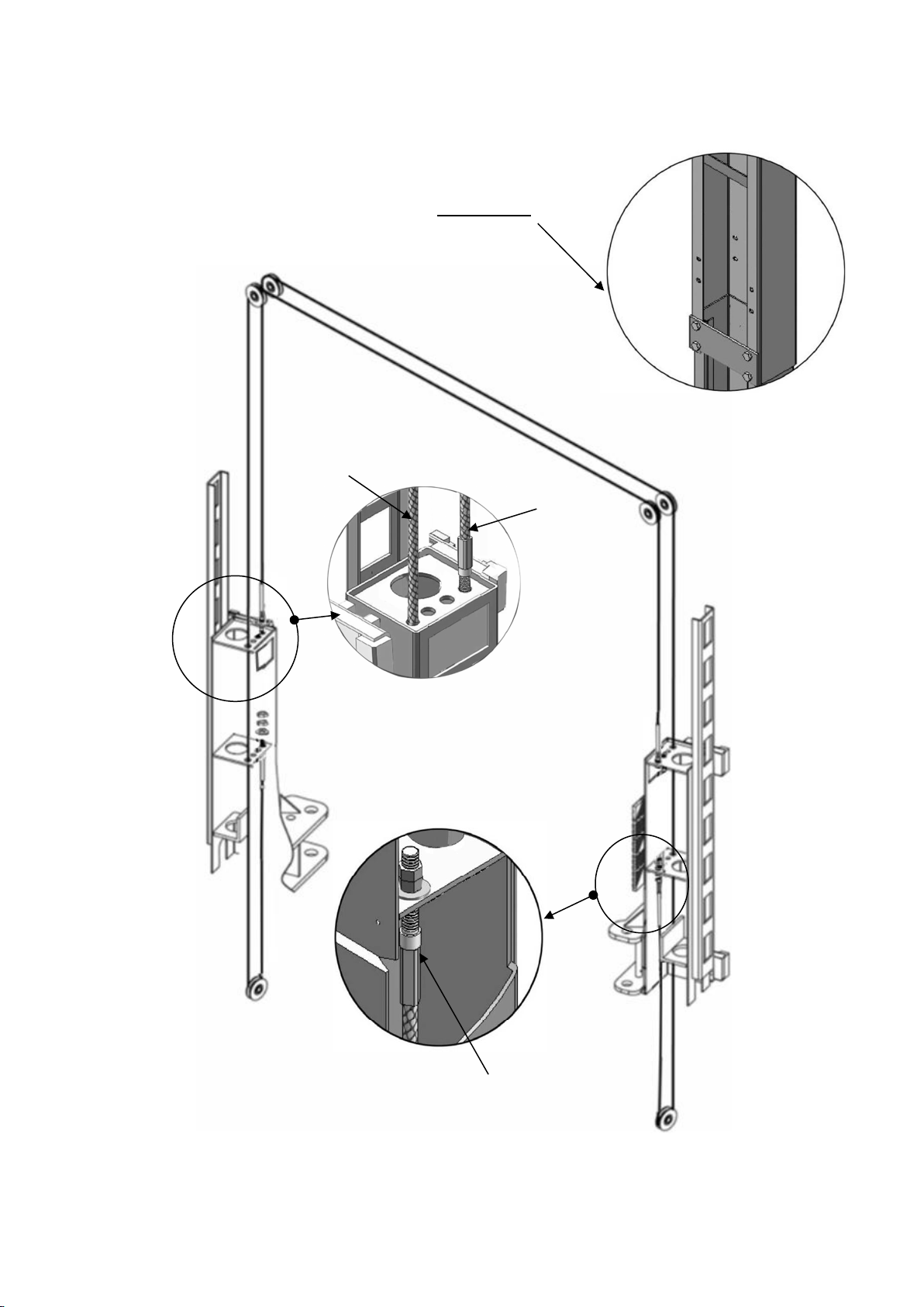
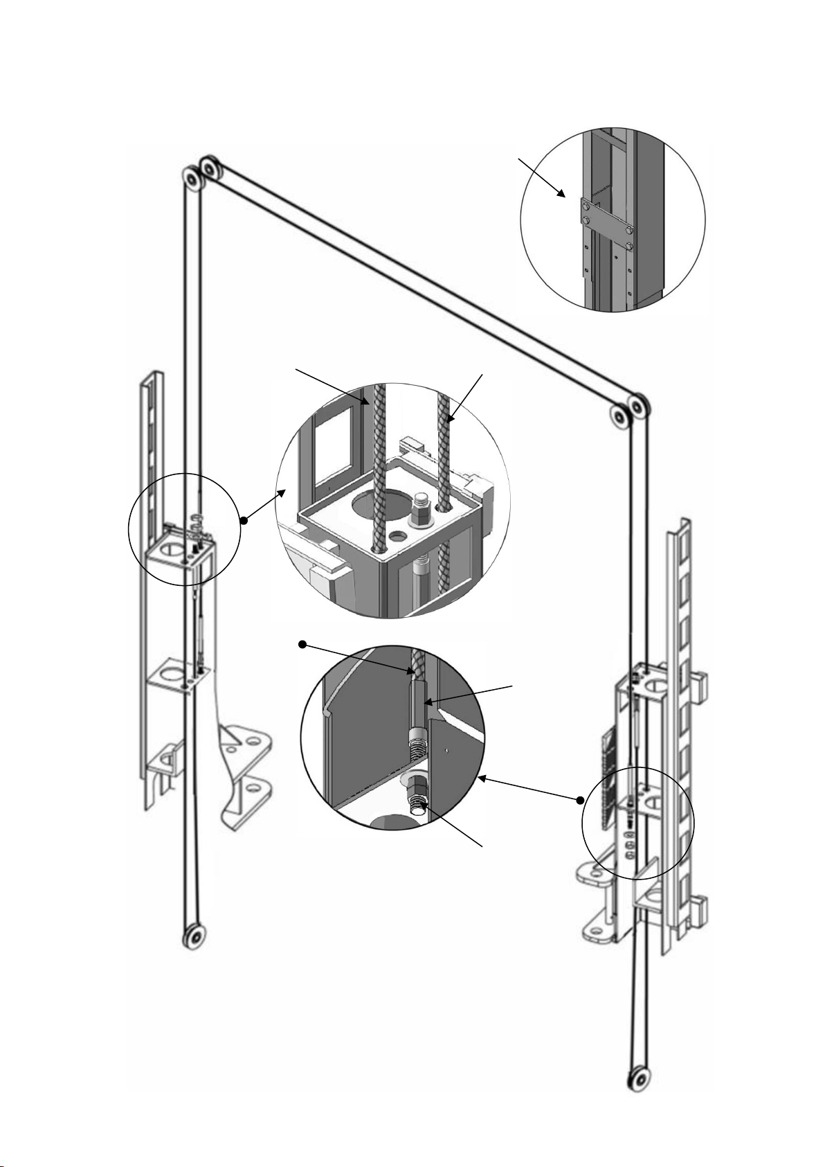
TWO-POST LIFT
MODEL: CL6800C
Original

CONTENTS
Product Features and Specifications ................................................1
Installation Requirement ...............................................................3
Steps of Installation .....................................................................5
Exploded View .............................................................................25
Test Run .....................................................................................34
Operation Instruction ...................................................................36
Maintenance ...............................................................................37
Trouble Shooting .........................................................................38
Scarping of equipment..................................................................38

1
I. PRODUCT FEATURES AND SPECIFICATIONS
CLEAR-FLOOR DIRECT-DRIVED MODEL FEATURES
Model CL6800C (See Fig. 1)
· Direct-drived design, minimize the lift wear parts and breakdown ratio
· Dual hydraulic cylinders are designed and manufactured according to high standard,
utilizing imported seals
· Self- lubricating UHMW Polyethylene sliders and bronze bush
· Single-point safety release with dual safety design
. Clear-floor design, provide unobstructed floor use
. Overhead safety shut-off device prevents vehicle damage
. Standard adjustable heights accommodate varying ceiling heights
MODEL CL6800C SPECIFICATION
Model
Style
Lifting
Capacity
Lifting
Time
Lifting Height
Overall Height
Overall
Width
Minimum
Pad Height
Motor
CL6800C
Clear-floor
Direct-drived
15,000lbs
(6800kg)
90s
1912~2141mm
174”/198”
(4420/5029mm)
150 3/4”
(3829mm)
7 1/4” -16 1/4”
(185-414mm)
4.0HP
Fig. 1

2
Arm Swings View
Fig. 2
3829mm
2787mm
109 3/4”
150 3/4”

3
II. INSTALLATION REQUIREMENT
A. TOOLS REQUIRED
Rotary Hammer Drill (Φ19) Carpenter’s Chalk
Hammer Screw Sets
Level Bar Tape Measure (7.5m)
English Spanner (12") Pliers
Wrench set:(10#、13#、14#、15#、17#Lock Wrench
19#、24#、27#、30#)
Ratchet Spanner With Socket (28#)
Fig.3
Socket Head Wrench (3#, 5#, 8#)

4
B. Equipment storage and installation requirements.
The equipment should be stored or installed in a shady, normal temperature,
ventilated and dry place.
C. The equipment should be unload and transfer by forklift.
D. SPECIFICATIONS OF CONCRETE (See Fig. 5)
Specifications of concrete must be adhered to the specification as following.
Failure to do so may result in lift and/or vehicle falling.
1. Concrete must be thickness 5”(120mm) minimum and without reinforcing steel bars,
and must be totally dry before lift installation.
2. Concrete must be in good condition and must be of test strength 3,500psi (245kg/cm²)
minimum.
3. Floors must be level with no cracks or holes.
E. POWER SUPPLY
The electrical source must be 3KW minimum. The source cable size must be 2.5mm² and
in good condition of contacting with floor.
Fig.4
Fig. 5
Concrete intensity must be 3,500psi
(245kg/cm²)
5”(120mm)
56

5
III.INSTALLATION STEPS
A. Location of installation
Check and ensure the installation location (concrete, layout, space size etc.) is
suitable for lift installation.
B. Use a carpenter’s chalk line to establish installation layout of baseplate (See Fig. 6)
C. Check the parts before assembly.
1. Packaged lift, hydraulic power unit and parts box; (Remark: Outer column is packed into
the machine) (See Fig. 7).
2. Move the lift aside with a fork lift or hoist, and open the outer packing carefully
(See Fig. 8).
Shipment Parts list
Fig. 7
Fig. 8
Outer column
Fig. 6
Parts box
Chalk a line
3829mm

6
3. Take out 2pcs outer column, then place the inner column to the installation location . (See
Fig. 9).
4. Lift the upper column with a fork lift or hoist, loosen the bolts of the upper package stand,
take out the parts in the inner column (See Fig. 10).
5. Lift the lower column with a fork lift or hoist, take down the package stand, than take off
the lower outer column, take out the parts in the inner column (See Fig. 11).
Fig. 9
Fig. 10
Fig. 11
Open the package
shelf

7
6. Move aside the parts and check the parts according to the shipment parts list
(See Fig. 12, Fig. 13)
7. Check the parts of the parts bag 1 according to parts bag list (See Fig. 14).
8. Check the parts of the parts bag 2 according to parts bag list (See Fig. 15).
Fig. 15
Fig. 14
Fig. 12
103
Fig. 13
Parts box list(103)

8
D. Install parts of extension columns (See Fig. 16).
E. Confirm the installation location and install hydraulic cylinder
Lay down two columns on the installation site parallelly, position the power-side column according to the
actual installation site. Usually, it is suggested to install power-side column on the right side of vehicles
driven-in. , and then put the cylinder into the carriages.(See Fig. 17).
1
52
69
67
Fig. 17
Fig. 16
20
37
25
24
26
41
42
The fitting of the cylinder
toward the hole

9
F. Install columns
This lift is designed with 2-Section columns. Adjustable height according to the ceiling height
and connecting the inner and outer columns.
If the ceiling height is over 5035mm, it can be installed in a high setting; if the ceiling height
between 4430mm-5035mm, it can be installed in the low setting; it is not allowed to install if
the ceiling height less than 4430mm.
1. High Setting, connecting the outer columns with the lower hole (See Fig. 19).
2. Low Setting: connecting the extension columns with the upper hole (See Fig.19).
Fig. 18 High setting
Fig. 19 Low setting
95
23
21
22

10
G. Install anchor bolts. Position the columns on the installation layout. Check the
columns verticality with level bar, and adjusting with the shim if the columns are
not vertical. Do not tighten the anchor bolts at this time. (See Fig.20)
Fig. 20
Adjusting with
the shim
Drilling
Cleaning
Bolting
4 3/8”
Note: Minimum embedment of anchors is 110mm.
57
56
Width between columns:
3137mm
Overall width:
3829mm

11
H. Install overhead top beam
1. With help of the hook of top beam, put one side of top beam on top of the extension column
and connecting the top beam to extension column by bolts, tighten the bolts. Then
assemble the connecting bracket (See Fig. 21).
Fig. 21
Hook on to the
extension columns
Tighten the bolts
23
22
21
27
1

12
2. Assemble overhead top beam, tighten the columns anchor bolts (See Fig. 22).
Tighten the anchor bolts
with ratchet spanner with
socket
Fig. 22
Note: Torque of Anchors is
150N.m.
27
28
23
22
21
a
1
52

13
A2
4
NC
N0
C
I. Installing the limit switch control bar and limit switch (See Fig. 23、Fig. 24).
A. Fix the control bar to the support bracket.
B. Installing the limit switch and wire.
1.Connect the wire:
Connect the red wire to terminal NC#,another side of the wire connect to the terminal A2 on
AC contactor of power unit.
Connect the black wire to terminal C#,another side of the wire connect to the terminal 4 on
control button of power unit.
Fix socket
bolt(M10*25mm)with
lock washer
adjustment
52
Power-side→
Off-side→
Fix the control bar support
bracket with Hex bolt
M10*20, self-locking nut
and washer
113
61
53
6
99
97
Control
bar
fixing
plate
Control bar
Installing
socket bolt
(M10*40mm)
with lock
washer
Connecting
Bush
Fig. 24
58
Fig. 23

14
2. Tighten limit switch .Fix the limit switch on control bar support bracket of the power-side as
the photo. The wire pass through the top beam and connected to the AC contactor of power
unit.
J. Install safety device (See Fig. 26 & Fig. 27).
Fig. 26 Power-side safety device
Fig. 27 Off-side safety device
12
13
14
15
16
17
1
8
7
10
11
100
24
18
19
9
21
6
12
13
14
44
45
17
52
19
18
40
50
24
51
24
100
47
46
43
38
39
Limit
switch
109
Fig. 25

15
K. Install cables
Raise both two carriages to the same level of lock.
1. High setting cable connection.
1.1 Take out the carriages plastic cover, cable pass through from the bottom of the carriages
and be pulled out from the open of carriages, then screw the two cable nuts (See Fig. 28).
Fig. 28
Cable connecting
direction
Cable connecting
direction
Tighten

16
1.2 Connecting cable for high setting (See Fig. 29)
Fig. 29
High setting
Cable 1
Cable 2
Cable 1

17
2. Low setting cable connection.(See Fig. 30).
107
Cable 1
Cable 2
Fig. 30
Low Setting
Cable 2
108

18
L. Install power unit (See Fig. 31)
Fig. 31
Right outlet port
Left outlet port
Iron Plug
A. Remove Iron Plug in the right side.
D. Install the iron plug from step A to
the oil outlet port on the left side.
C. Remove the red plug in the left side.
Red Plug
B. Install power unit 90° fitting.
107
Table of contents
Other CLASSIC LIFT Lifting System manuals
Popular Lifting System manuals by other brands

Braun Corporation
Braun Corporation NL501 Series Service manual

Guldmann
Guldmann Stepless LP1 manual

Fieldmann
Fieldmann FDAD 6201 instruction manual

Nussbaum
Nussbaum MCS 7500 Operating Instruction and Documentation

LGMG
LGMG SR3369E Service manual

AAQ
AAQ AutoLift AL-3000AG Installation manual & operation instructions