CLASSIC LIFT CL4500XH Manual

TWO-POST LIFT
Model:CL4500XH
Original

CONTENTS
Product Features and Specifications ................................................1
Installation Requirement ...............................................................3
Steps of Installation .....................................................................5
Test Run .....................................................................................20
Operation Instruction....................................................................22
Maintenance Schedule ..................................................................23
Trouble Shooting .........................................................................24
Exploded View .............................................................................25
Lift Disposal ......................................................................................33

1
I. PRODUCT FEATURES AND SPECIFICATIONS
CLEAR FLOOR DIRECT-DRIVED MODEL FEATURES
MODEL CL4500XH (See Fig.1)
· Direct-driving design, minimize the lift wear parts and breakdown ratio.
· Dual hydraulic direct-drive cylinders, designed and made as US standard, utilizing
imported oil seal in cylinder.
· Self-lubricating UHMW Polyethylene sliders and bronze bush.
· Single-point safety release, and dual safety design.
· Clear-floor design, provide unobstructed floor space.
· Overhead safety shut-off device.
·With 4 three stages arms, make lifts easily find the lift point of the car.
· Stackable adapters 1.5”, 2.5”, 5” as standard.
· Two pieces columns design provide two installation height.
MODEL CL4500XH SPECIFICATIONS
Model
Lifting
Capacity
Lifting Height
Lifting
Time
Overall Height
Overall
Width
With
Between
Columns
Minimum
Pad Height
Motor
CL4500X
H
4500KG
2000~2290mm
64s
4035/4313mm
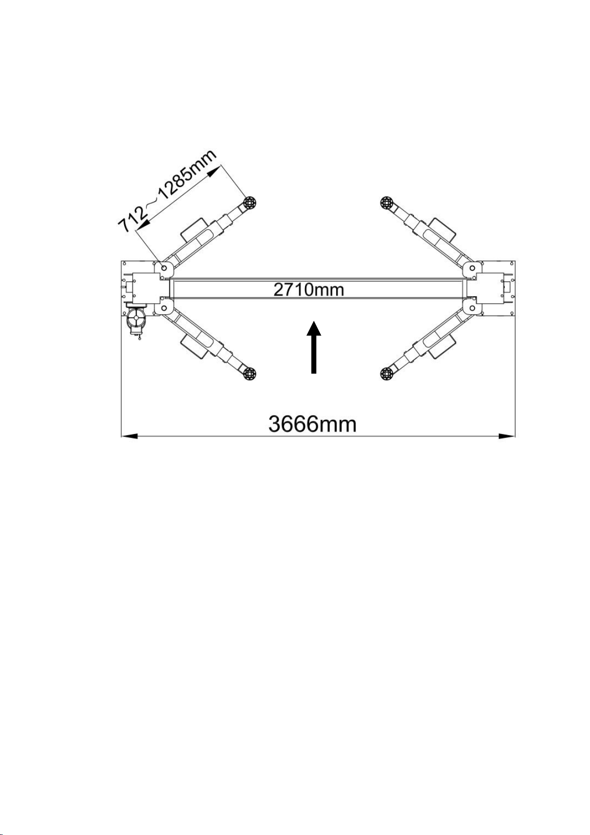
3666mm
3000mm
90mm
3.0HP
Fig. 1
2
Arm Swings View
For Model CL4500XH
Fig. 2
Drive in

3
II. INSTALLATION REQUIREMENT
A. TOOLS REQUIRED
Rotary Hammer Drill (Φ19)
Hammer
Level Bar
English Spanner (12")
Ratchet Spanner With Socket (28#)
Wrench set
(10#, 13#, 14#, 15#, 17#, 19#, 24#,27#)
Carpenter’s Chalk
Screw Sets
Tape Measure (7.5m)
Pliers
Socket Head Wrench (3#, 6#)
Lock Wrench
Fig. 3

4
B. Equipment storage and installation requirements.
The equipment should be stored or installed in a shady, normal temperature,
ventilated and dry place.
C.The equipment should be unload and transfer by forklift.
D. SPECIFICATIONS OF CONCRETE (See Fig. 10)
Specifications of concrete must be adhered to the specification as following.
Failure to do so may result in lift and/or vehicle falling.
1. Concrete must be thickness 100mm minimum and without reinforcing steel bars,
and must be dried completely before the installation.
2. Concrete must be in good condition and must be of test strength 3,000psi
(210kg/cm²) minimum.
3. Floors must be level without cracks.
E. POWER SUPPLY
The electrical source must be 2.2KW minimum. The source cable size must be
2.5mm² and in good condition of contacting with floor.
Fig. 5
Concrete intensive must be
210kg/cm² minimum
67
Fig.4
100mm

5
III. STEPS OF INSTALLATION
A. Location of Installation
Check and insure the installation location (concrete, layout, space size etc.) is
suitable for lift installation.
B. Use a carpenter’s chalk line to establish installation layout of base plate (See Fig. 6).
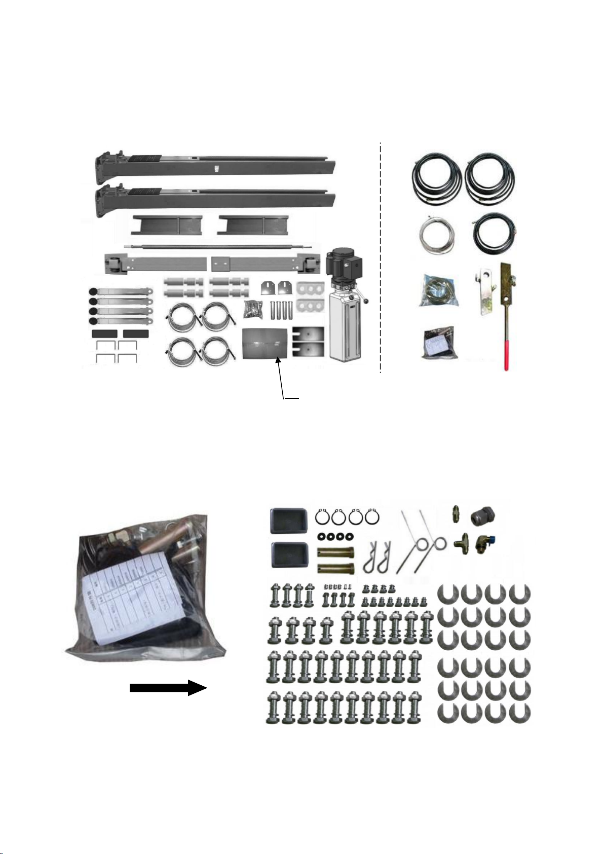
C. Check the parts before assembly
1.Packaged lift and hydraulic power unit (see Fig. 7)
2. Move the lift aside with a fork lift or hoist, and open the outer packing carefully ,
take off the parts from upper and inside the column, take out the parts box,check
the parts according to the shipment parts list (See Fig. 8).
Fig.6
Fig. 7
Shipment Parts
list
Serial number
Top beam
Fig. 8
Chalk Line
Parts box.
3666mm
6
3. Loose the screws of the upper package stand, take off the upper column and remove
the package stand.
4. Move aside the parts and check the parts according to the shipment parts list
(See Fig. 9, 10).
5.Open the bag of parts and check the parts of the parts bag according to parts bag
list (See Fig. 11).
Fig. 11
40
Fig. 9
Parts in the shipment parts list
Fig. 10
Parts in the parts box (40)
7
41
14
69
41
14
High Setting
Low Setting
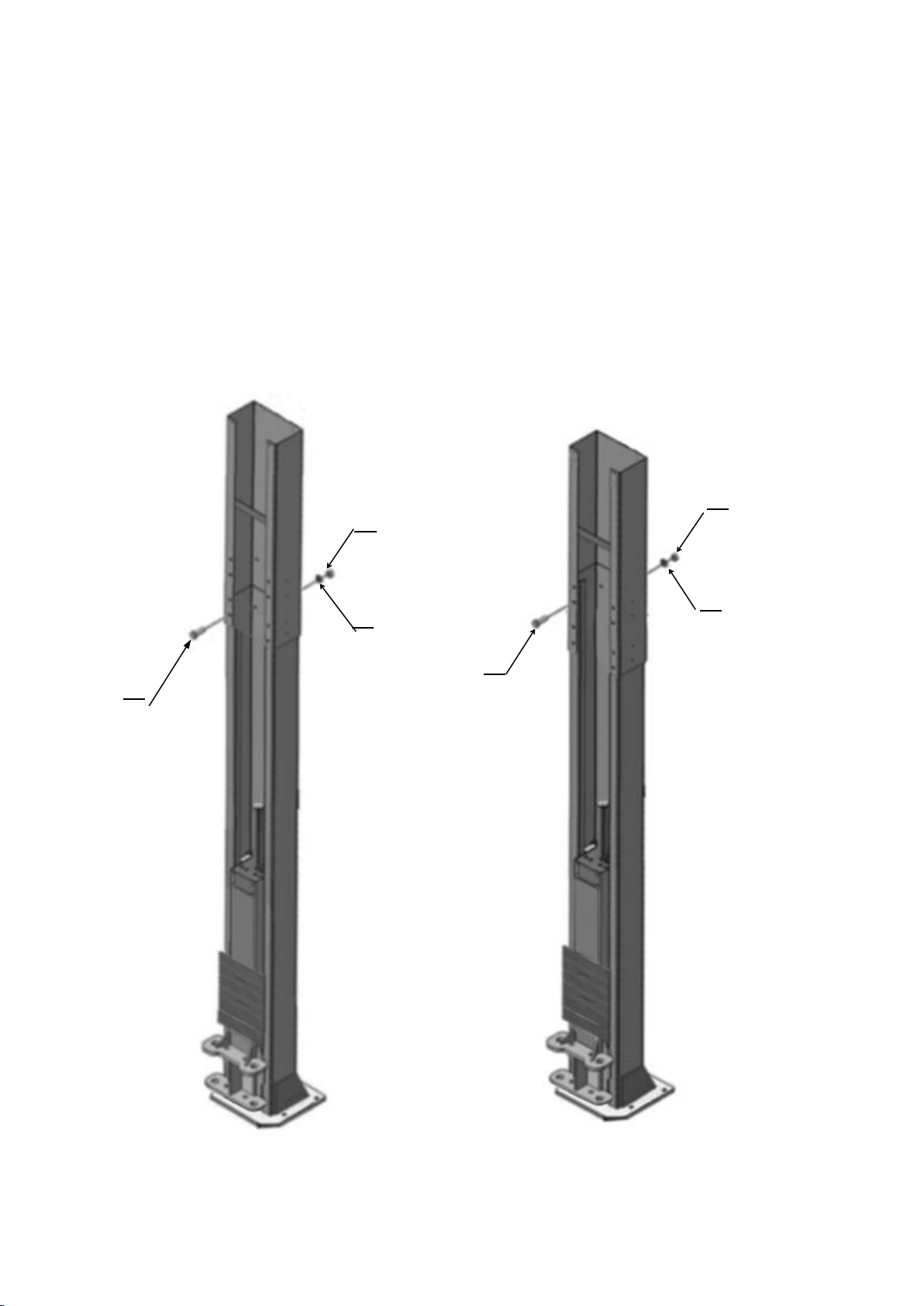
D. Position power side column
Lay down two columns on the installation site parallel, position the power side
column according to the actual installation site. Usually, it is suggested to install
power-side column on the right side of vehicles enter direction. (See Fig. 12).
This lift is designed with 2-section columns. Adjustable height according to the
ceiling height and connecting the inner and extensions columns.
Ceiling height over 4343mm, can be both low setting/high setting,
Ceiling height between 4065-4343mm, only available low setting.
Minimum ceiling height: 4065mm
Fig. 12
69
8
1
57
67
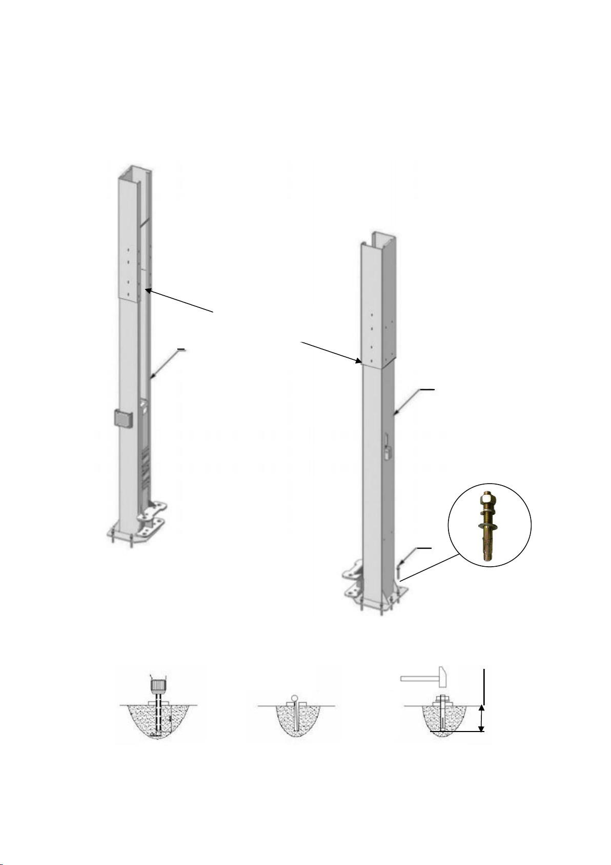
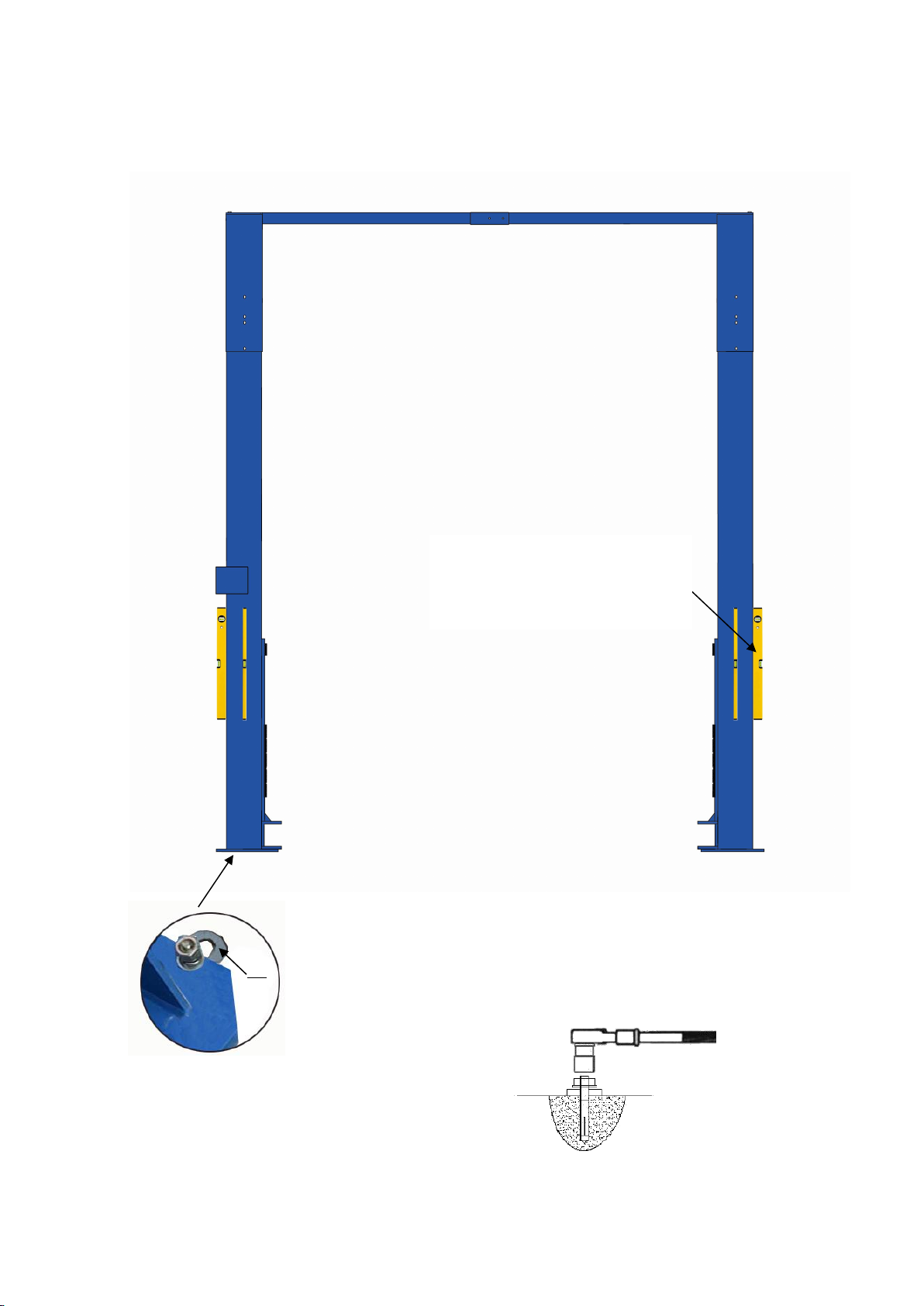
E. Position columns
Place the columns on the installation layout of base plate. Install the anchor bolts.
Do not tighten the anchor bolts (See Fig.13).
Anchor Bolt
Fig.14
Cleaning
Bolting
Drilling
≥90mm
Note: Minimum embedment of anchors is 90mm.
Width between
column: 3000mm
Fig.13

9
50
71
F. Mounting the top beam . Fig.15
Fig.15
52
51
41
14
10
71
41
G. Check the vertical of the columns with level bar, and adjusting with the shims if the
columns are not vertical. Tighten the anchor bolts (See Fig.16).
Adjusting with the shims
Fig. 16
Note: Torque of Anchors is
150N.m
Check the plumbness of the
column from front and side
with a lever bar
68
11
47
47
47
47
41
41
45
45
45
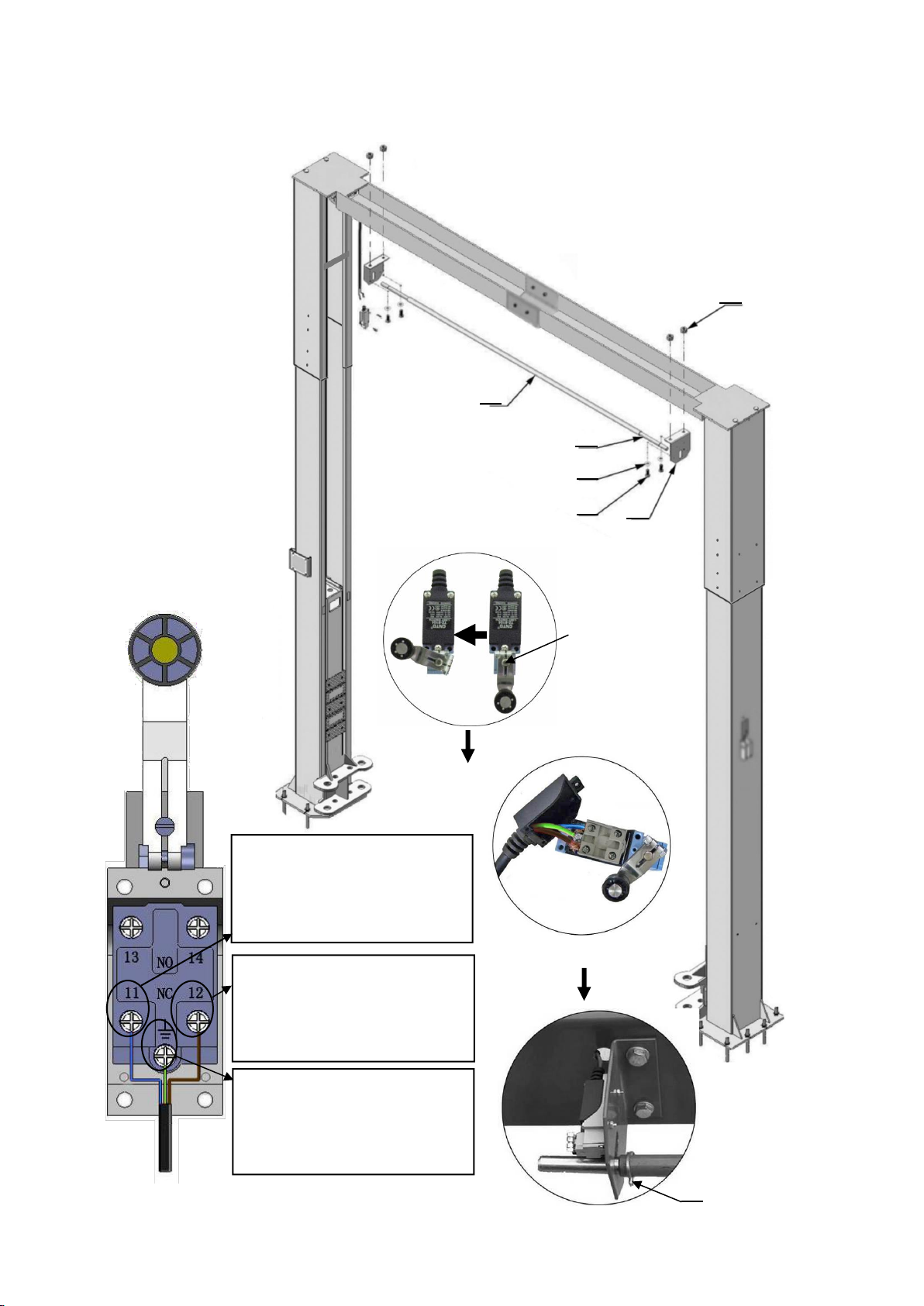
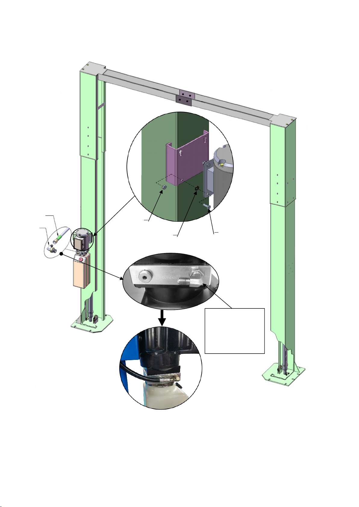
H. Install the limit switch control bar and limit switch (See Fig. 17).
NC: Normal contact
Fig. 17
Use 3# Socket Head
Wrench to loosen the
Screw of drive rod
for adjustment
Limit switch connect
the wire
Connect the blue wire to
terminal #11 on limit switch
and terminal A2 on AC
contactor of power unit.
Connect the brown wire to
terminal #12 on limit switch
and terminal #4 on button of
power unit
Connect the yellow and green
wire to earth wire terminal on
limit switch and earth wire
terminal of power unit
46
47
41
45
14
42
43
12
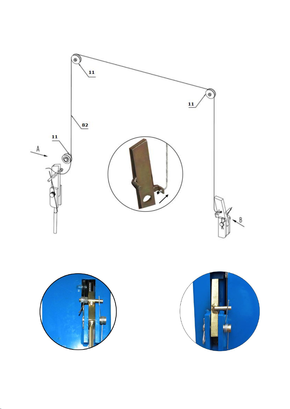
I. Install safety cable & Safety Device (See Fig. 18).
View A
Fig. 18
Cable Through Direction
View B

13
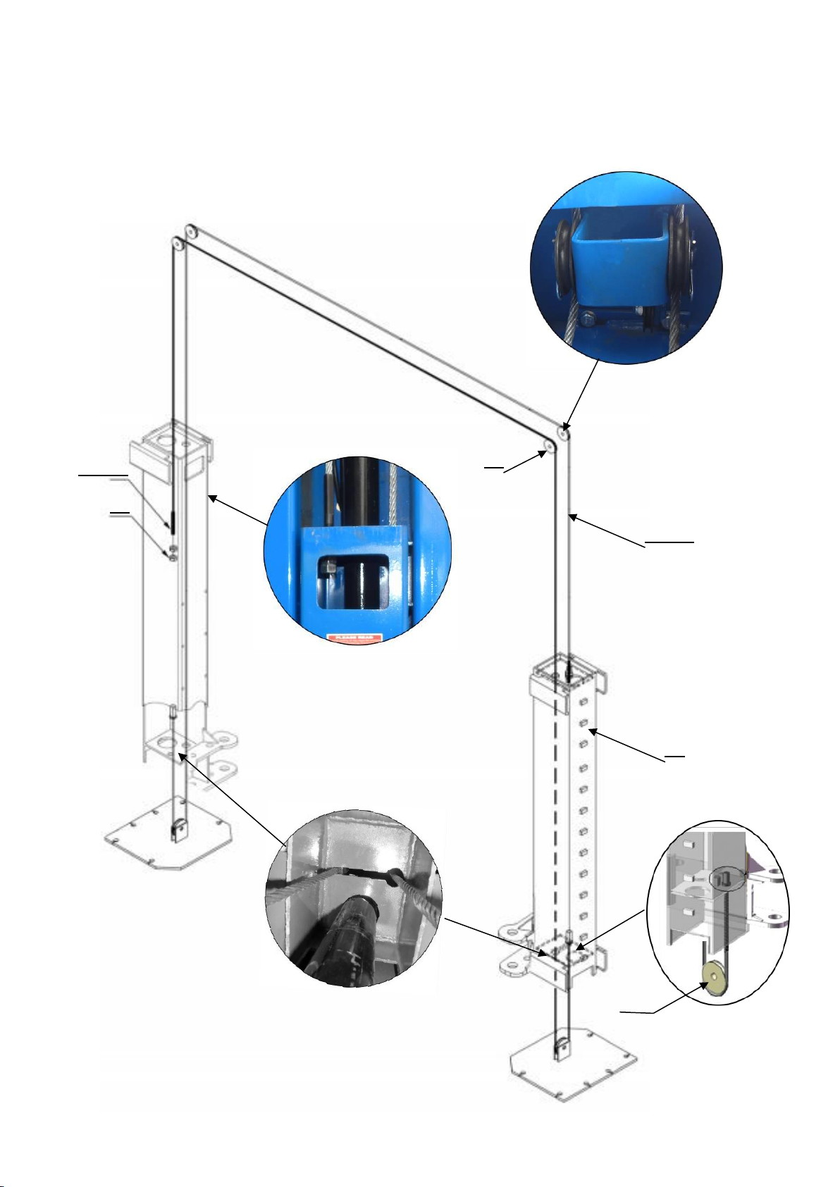
J. Lift the carriages up by hand and make them be locked at the same level
(See Fig. 19).
Note:Make Sure the carriages is locked by safety guard.
Ensure both carriages lock
at the same level lock
Fig. 19
14
72/73
74
K. Install cables (See Fig. 20).
Note: The cables for high setting and low setting are different.
High Setting: φ9.5*10473mm
Low Setting: φ9.5*9915mm
Fig. 20
54
72/73
20
65

15
L. Assembly oil hose,tighten all the fitting for oil hose. See fig.21
No.78 & 79 only for high setting
75
80
17
17
75
80
75
76
78
75
77
75
79
76
Fig. 21
16
M. Install power unit and oil hoses (See Fig. 22)
Pay attention to lock the fitting for hose and power unit to prevent oil leakage
N. Tighten all the hydraulic fittings, and fill the reservoir with hydraulic oil.
Note: In consideration of Hydraulic Power Unit’s durability and keep the equipment
running in the perfect condition, please use Hydraulic Oil 46#.
Fig. 22
3
5
4
76
81
Tighten the nut
with #19 wrench
after install the
fitting.
17
O. Install electrical system
Connect the power source on the data plate of power unit.
Note: 1. For safety of operators, the power wiring must contact the floor well.
2. Pay attention to the direction of rotations when using three phase motors.
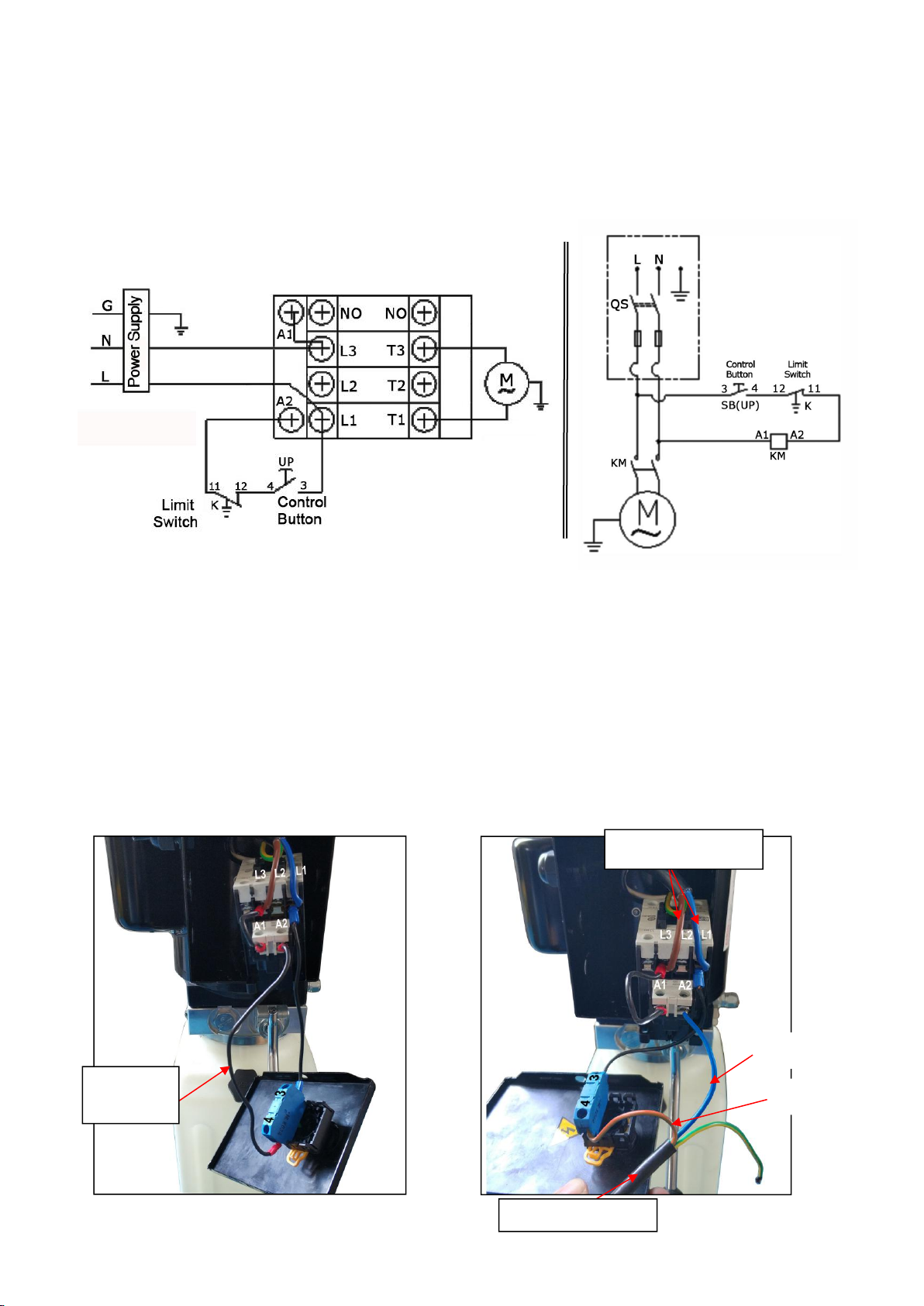
Single phase motor.
1. Circuit diagram (See Fig.23)
2. Connection step
a. Connecting the two power supply wires (active wire Land neutral wire N) to
terminals of AC contactor marked L1, L3respectively.
b. Connecting the limit switch: Removing the wire of connecting terminal 4# of
control button and A2of AC contactor firstly (See Fig. 24), then connecting wire
12#(brown wire) of limit switch with terminal 4# of control button and connecting
wire 11#(blue wire) with terminals A2of AC contactor respectively. Connecting the
earth wire of limit switch to the earth wire terminal on the motor. (See Fig.25).
c. Terminals 3# of control button is connected with L1 terminals of AC contactor.
Fig.25
Fig. 24
Fig. 23
Remove
this wire
Wire 11#
Limit switch wire
Wire 12#
Power supply wires
18
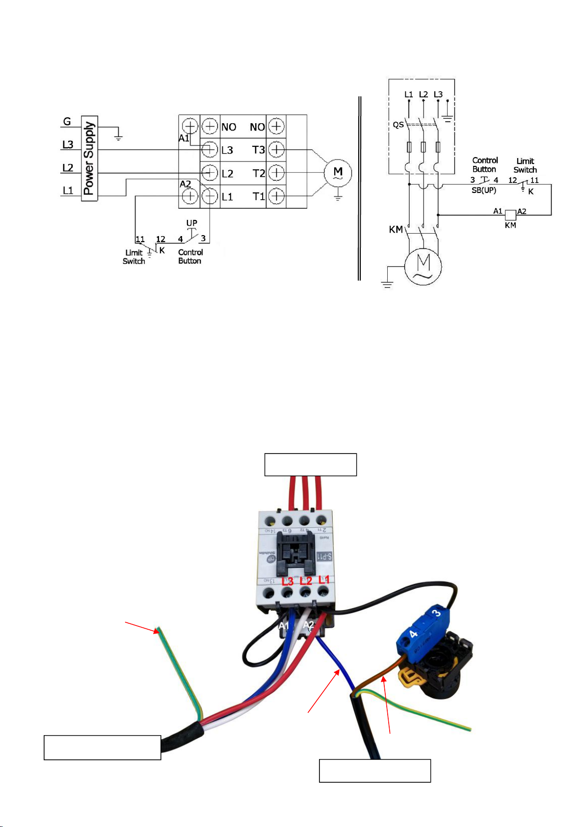
Three phase motor
1. Circuit diagram (See Fig. 26)
3. Connection step (See Fig.27)
a. The power supply wires(L1, L2, L3) are connected with terminals of AC contactor
marked L1, L2, L3 respectively.
b. Terminals 4# of control button is connected with wire 12#(brown wire)of limit
switch; wire 11#(blue wire) is connected with A2terminal of AC contactor, Earth
wire( yellow and green wire) of limit switch is connected with the earth wire
terminal of the motor.
c. Terminals 3# of control button is connected with L1 terminals of AC contactor.
Wire 11#
3
Wire of limit switch
Wire 12#
Power supply wires
Wire of motor
Earth wire
Fig. 27
Fig.26
Table of contents
Other CLASSIC LIFT Lifting System manuals


Popular Lifting System manuals by other brands


Vestil
Vestil RR Series instruction manual

APlusLift
APlusLift SL-MR80 Installation, operation & maintenance instructions

EAE
EAE EE-MR35 Installation, operation, and parts manual

Sealey
Sealey HPT150.V2 Instructions for use

Liko
Liko Sabina Assembly instruction

Extreme Max
Extreme Max Boat Lift Boss 3005.7269 installation instructions