8
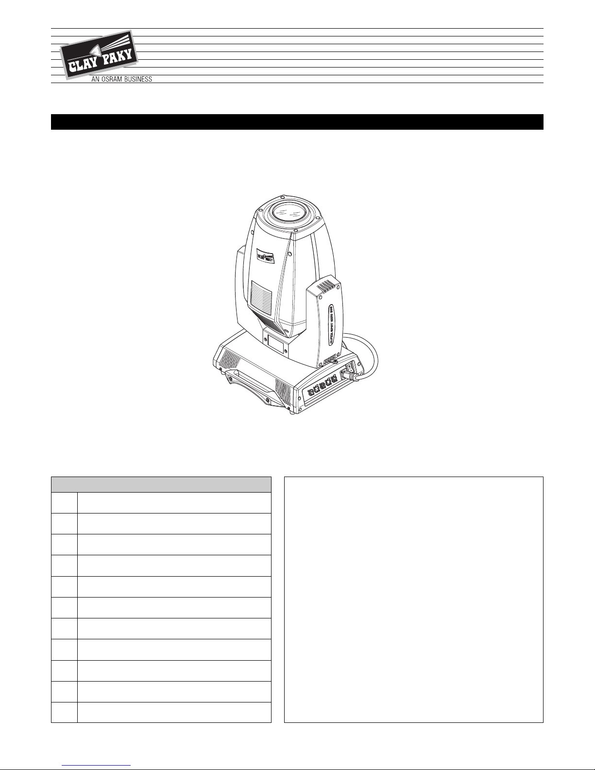
ALPHA SPOT QWO 800 & “ST”
DMX ADDRESS
NOTE: without the DMX signal the Address (XXX) flashing
Allows you to select the DMX ADDRESS.
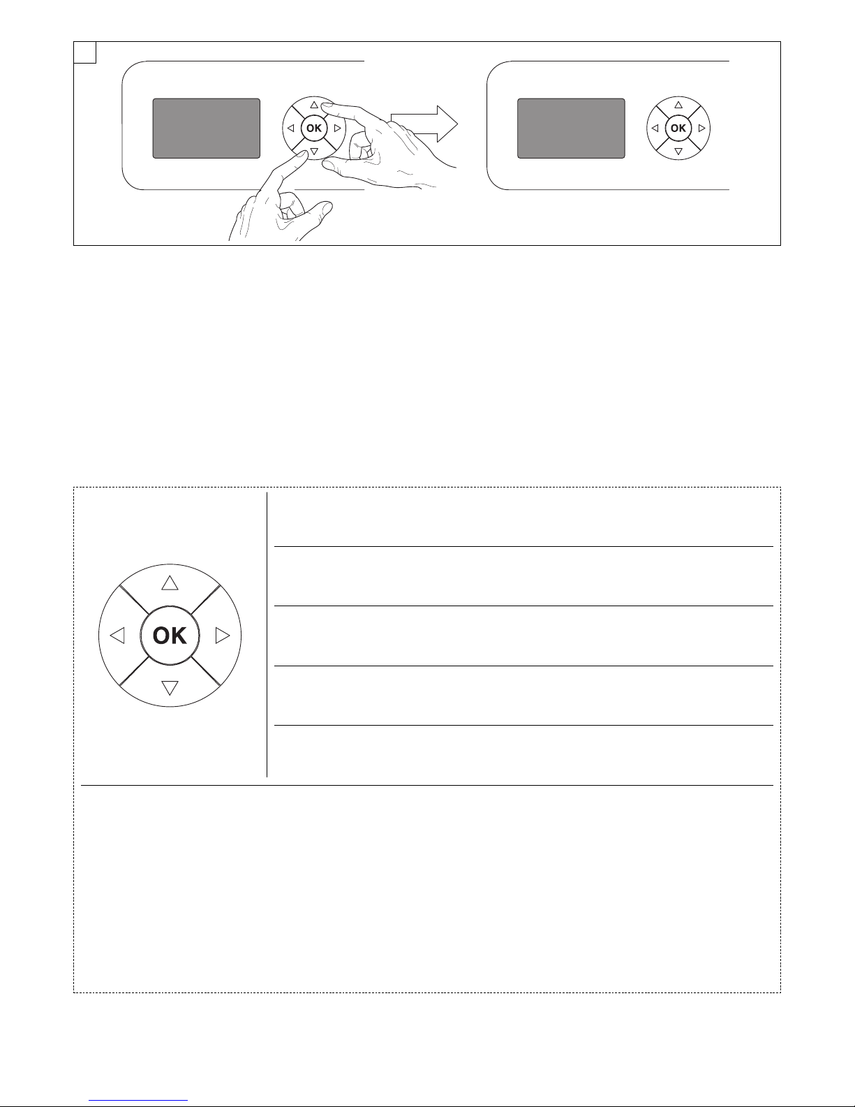
1) Press
F
- the current DMX Adress appear on the display.
2) Use the UP
B
and DOWN
C
, RI HT
E
keys to plan the DMX
Address.
3) Press
F
to confirm the selection or LEFT
D
to keep current settings.
C ANNEL MODE
Allows you to select a channel arrangement from the two available.
1) Press
F
- the current settings appear on the display (Standard or
Vector).
2) Use the UP
B
and DOWN
C
keys to select one of the following
settings:
- Standard
- Vector
3) Press
F
to confirm the selection or LEFT
D
to keep current settings.
FIXTURE ID
Allows you to select the FIXTURE ID.
1) Press
F
- the current Fixture ID appear on the display.
2) Use the UP
B
, DOWN
C
, RI HT
E
keys to plan the Fixture ID.
3) Press
F
to confirm the selection or LEFT
D
to keep current settings.
ET ERNET INTERFACE
It lets you set the Ethernet settings to be attributed to the projector.
1) Premere
F
.
2) Use the UP
B
and DOWN
C
keys to select the “Ethernet Interface”
options to set:
Control Protocol
It lets you select the “Control Protocol” Art-net to assign according to the
control unit used:
1) Press
F
the current setting appears on the display.
2) Use the UP
B
and DOWN
C
keys to select one of the following settings:
- Disabled
- Art-net on IP 2
- Art-net on IP 10
- Art-net Custom IP
3) Press
F
to confirm the selection or LEFT
D
to keep the current setting.
If the Control Protocol option is set on Disabled, when an IP address (IP2,
IP10 or IP Custom) is selected, the projector immediately initializes the IP
address that was just selected. If the Control Protocol option is enabled (IP2,
IP10 or IP Custom) and a new one is selected that is different from the
previous one, the projector must be restarted so that it will be correctly
initialized.
Repeat on DMX
It lets you enable the transmission of the Ethernet protocol by DMX signal
to all the connected projectors.
1) Press
F
the current setting appears on the display.
2) Use the UP
B
and DOWN
C
keys to select one of the following settings:
- Disabled: DMX transmission disabled.
- Enabled on primary: DMX transmission enabled.
3) Press
F
to confirm the selection or LEFT
D
to keep the current setting.
Universe
It lets you assign the “Universe” number to be assigned to a series of
projectors.
1) Press
F
– the current Universe address appears on the display.
2) Use the UP
B
, DOWN
C
, RI HT
E
keys to set the Universe address.
3) Press
F
to confirm the selection or LEFT
D
to keep the current setting.
Custom IP address
Allows you to set the IP address manually by the user default.
Custom IP mask
Allows you to set manually the Subnet Mask by the user default.
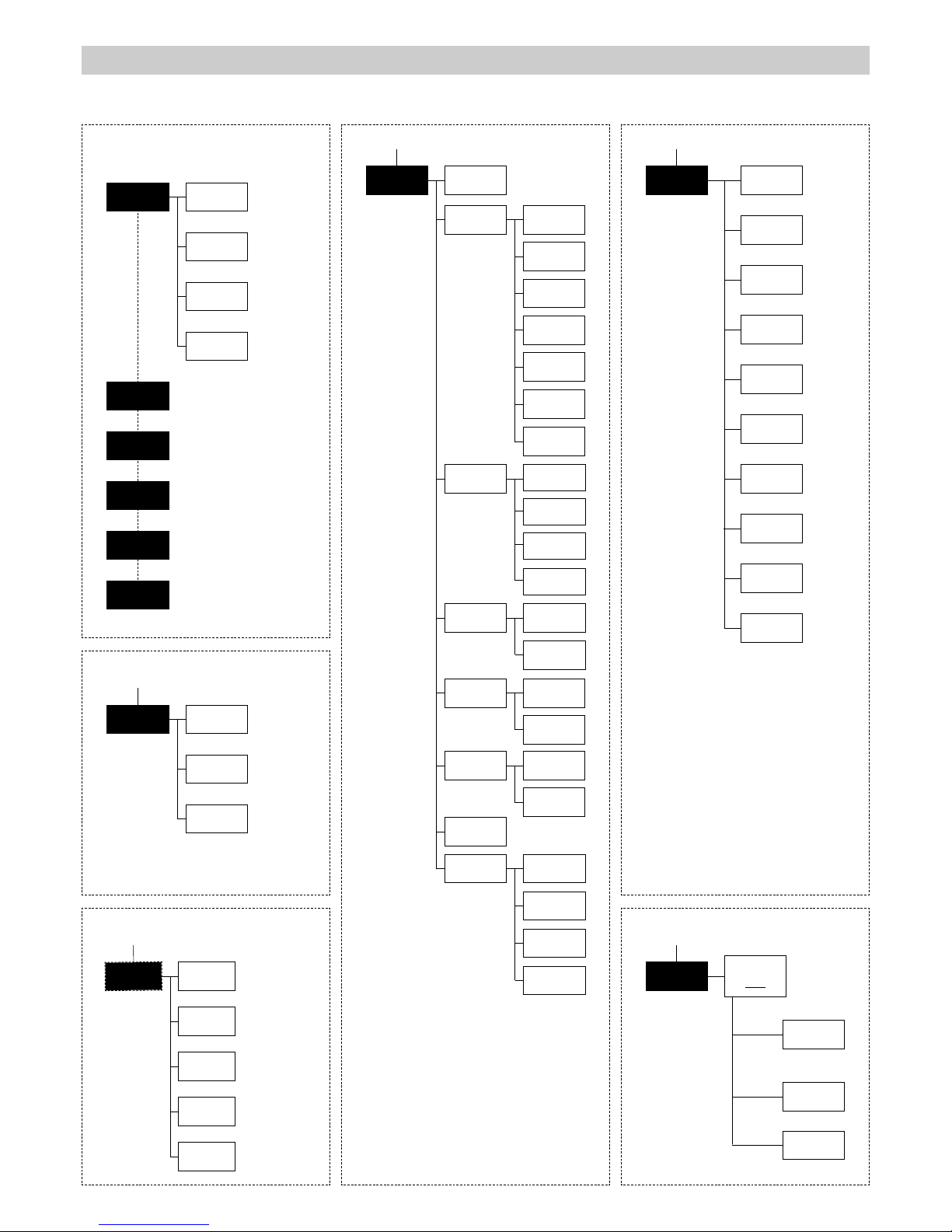
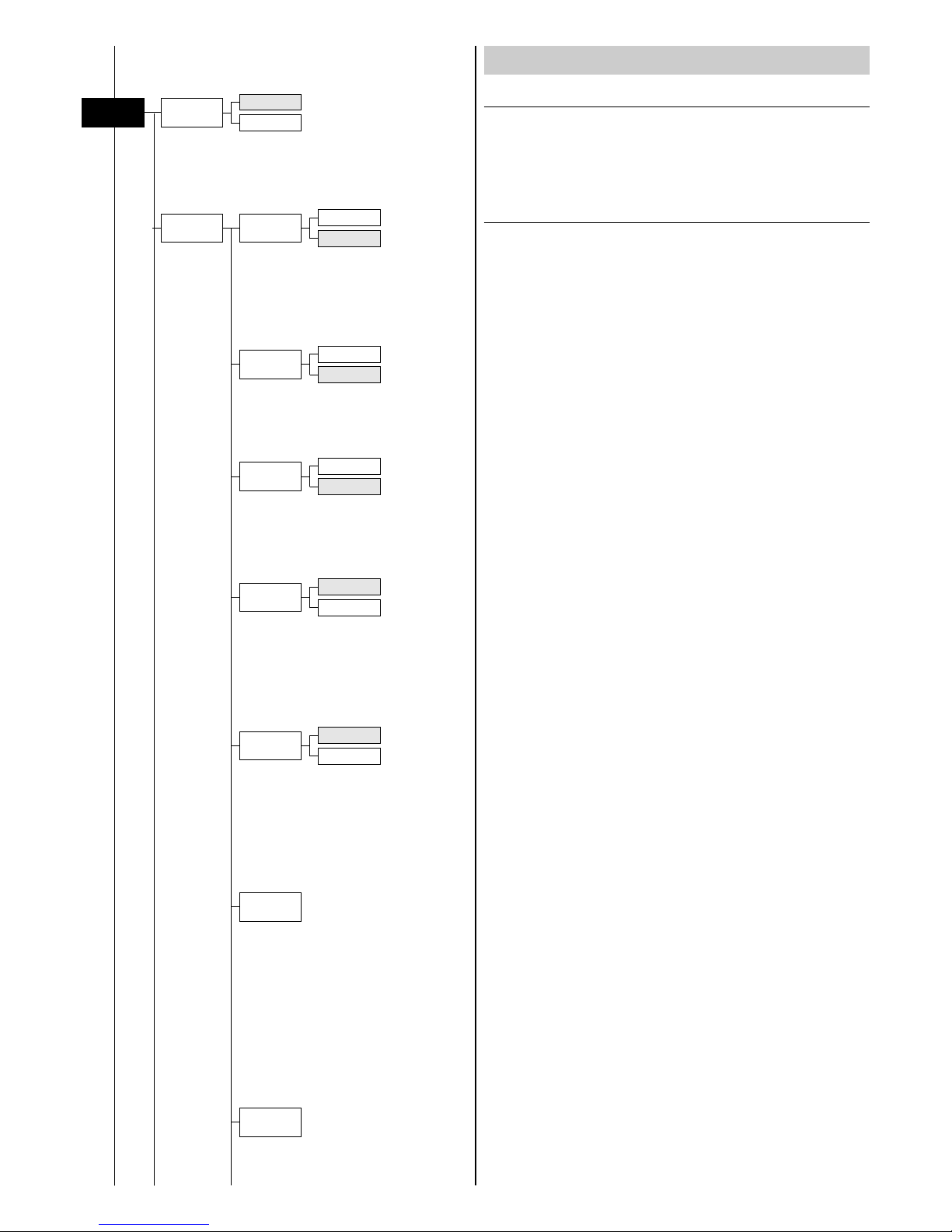
SET UP MENU
Set Up Dmx
Address
Channel
Mode
Fixture ID
Address xxx
Standard
Vector
Value xxx
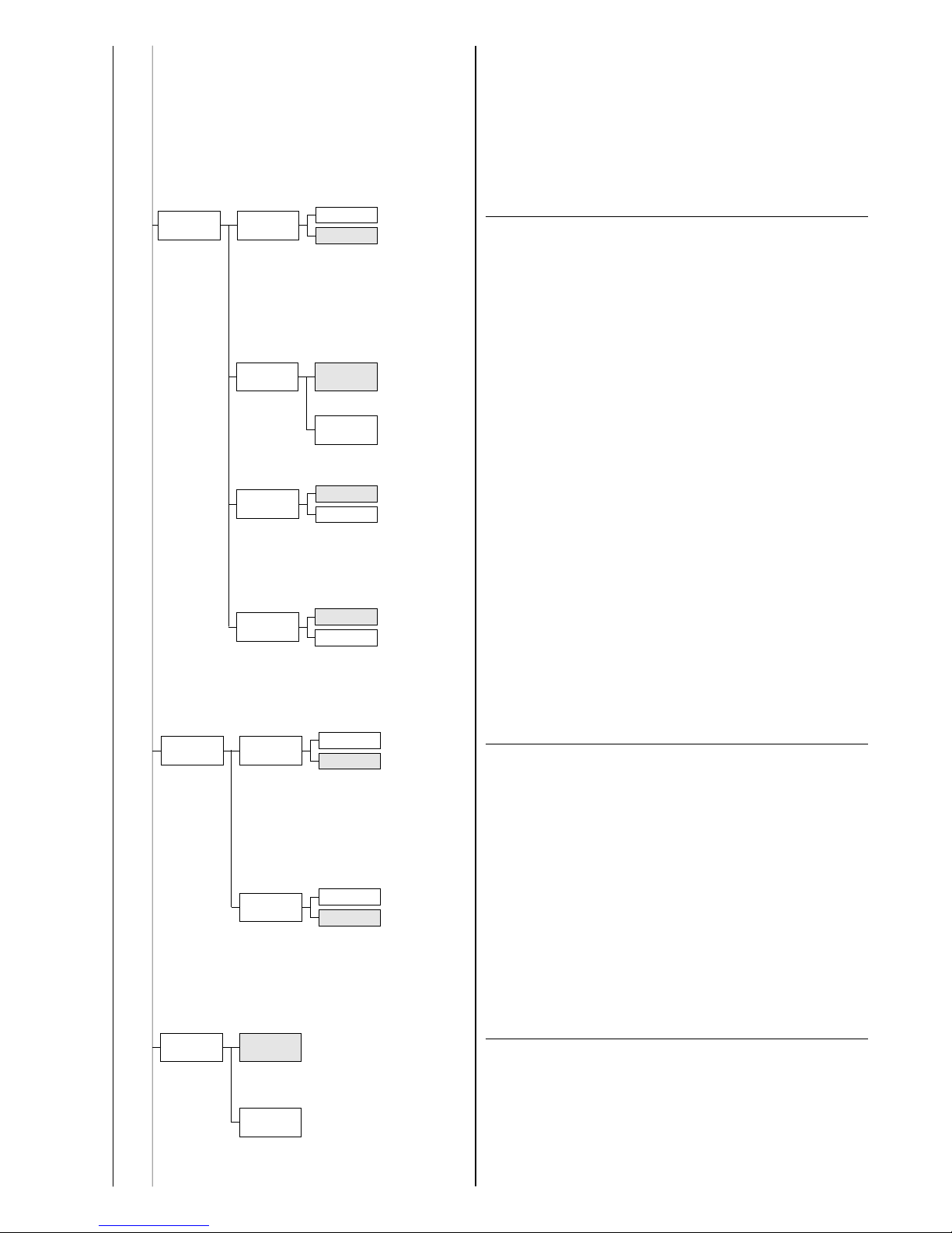
Ethernet
Interface
Control
Protocol
Repeat on
DMX
Universe
NOTE: On grey the default options
Custom IP
address
Custom IP
mask