CLEAN ROOM DEVICES CRD222 User manual

1
CRD222 HEAVY-DUTY AUTOMATIC
TUBING EXPANDER
OPERATIONS MANUAL
ORIGINAL INSTRUCTIONS
VERSION 2.5
LAST EDITED 05.1.2022
cleanroomdevices.com

2
Table of Contents
Title Page……………………………………….……………..……………………………….…1
Table of Contents…………………….…………………………………………………………..2
1.0 General Product & Safety Information…………………………………………….…….3
1.1 Product Information
1.2 Safety Information
2.0 Installation………………………………………………….………………..….………..4
2.1 Air Supply
2.2 Electrical
2.3 Connection Setup
3.0 Operation…………………………………………………………………..……...…..….5
3.1 Jaw Adjustment
3.2 Setting Time Delays
3.3 Expanding Operation
3.4 Jaw Installation and Removal
4.0 Troubleshooting………………………………………….……………….…………..…13
5.0 Maintenance…………………………………………………………………….…….…14
5.1 Periodic Cleaning (annually)
5.2 Tools List
6.0 Product Specifications……………………………………………………………….…..14
7.0 Durometer Scale…………………………………………………………………………14
8.0 Wiring Diagram……………………………………………………………….…………15
9.0 Warranty…........................................................................................................................16
9.1 Warranty
9.2 Warranty period

3
1.0 General Product & Safety Information
1.1 Product Information
•Unit is designed to expand flexible tubing up to a durometer of Shore A 85 (Shore D 35),
including any non-metallic braided materials
•The minimum/maximum inside tube diameter is 7/16” – 3/4”
•The expander jaws are universal in design to meet most applications
•The device features simple yet reliable jaw adjustment, which can be made by the
operator.
•The device features a calibrate-able pressure gage conveniently mounted for additional
process control.
•The device features independently adjustable expansion and interval period adjustments
from 0.5-5 seconds, allowing for repeatability of operation.
•The serial number for the device is located on the bottom, rear of the base.
Figure 1.1
1.2 Safety Information
•This product uses an air cylinder and sensor or foot pedal to pneumatically actuate the
expanding jaws. The unit is not intended to expand anything other than flexible tubing.
Avoid placing your fingers between the upper jaw block and the air cylinder mounting bracket while
operating unit, sufficient pressure exists to cause personal injury.
WARNING

4
Arrows indicate pinch points
•The air supply should be free of moisture/contaminates, and set to a minimum of 100 psi.
It is recommended that a suitable filter/regulator be installed onto the supply line prior to
the unit to preserve the life expectancy of the air components.
2.0 Installation
Ensure all five (5) rubber feet are completely stabilized on your work surface prior to applying
air pressure to the unit.
2.1 Air Supply
•Connect a 1/4” OD air supply hose to the inlet on the pressure regulator. The air supply
should be free of moisture and contaminates and provide a minimum of 100 psi.
•The regulator on the unit should be set to 80-120 psi.
2.2 Electrical
•120 to 240V AC power supply required for operation. The unit will come with the
appropriate 24 VDC power supply.
2.3 Connection Setup
Setting up the connections on the CRD222 is a simple task. Please reference Figure
2.3.1 below when making all connections to the back panel:

5
Figure 2.3.1: Electronics enclosure connections
3.0 Operation
3.1 Jaw Adjustment
•Start by using a 9/16” wrench to loosen the 3/8” hex nut at the bottom end of the lower
jaw support block assembly to adjust the unit for the proper tubing size.
•With A/C power and compressed air attached to the expander, actuate the sensor or
optional electric foot switch, which will activate the expander. Adjust the expander
lower jaw to the position you want using the Thumb Wheel Knob. Note that the jaws
may be set to remain in the “open” position using the toggle switch noted in Figure 3.3.1,
and triggering the foot pedal. Make sure the toggle switch is returned to the “off”
position, or the jaws will remain open.
•Locate the lower expander jaw position for your tubing size using the larger thumb-
wheel.
(This adjustment may require fine tuning depending on your tubing I.D., O.D.,
Durometer or material. It is recommended you note or log the jaw gap settings for future
applications, or usage.)
•Next, tighten the thumb-wheel against the lower mounting block and secure in place
using the 9/16” wrench to snug the 3/8” hex nut against the bottom of the lower jaw
support block assembly. Be careful that you do not over tighten the nut.
Sensor
Toggle
Switch
Foot Pedal Jack
Power Jack
On
Off
Jaw Hold-Open
Toggle Switch
On
Off

6
Figure 3.1.1: Jaw Adjustment
•Next, tighten the thumb-wheel against the lower mounting block and secure in place
using the 9/16” wrench to snug the 3/8” hex nut against the bottom of the lower jaw
support block assembly. Be careful that you do not over tighten the nut.
3.2 Setting the Time Delays
•The CRD222 expansion operation is designed to expand each piece of tubing twice.
After the first expansion, the jaws will close and the operator rotates the tube 90 degrees
and the jaws will automatically expand again using the sensor. This ensures that the
tubing is expanded in a uniform fashion, and not deformed in only one direction. To
assist with this 2-step expansion operation, there are two time delays on the unit.
oExpansion Time –This setting adjusts the rate (0.5-5.0 seconds) at which the
tube expansion occurs. The rate at which the tube is expanded is critical to
prevent tearing. Some stiffer tubing might need a longer expansion time, while
softer tubing can be expanded rapidly.
oInterval Time –This setting adjusts the time delay rate (0.5-5.0 seconds) at
which the jaws will cycle. It is adjusted to allow the operator to rotate the tubing
90 degrees at a comfortable pace between expanding.
•Remove the hole plugs with a screwdriver on the rear cover to gain access to the Time
Delay adjustment pots. Figure 3.2.1
•Using a small Phillips drive screwdriver adjust the Time Delay relays.
Thumb Wheel
Lock Nut

7
Figure 3.2.1: Removing Access Hole Plugs
•Using a small Phillips drive screwdriver adjust the Time Delay relays. Figure 3.2.2
Turn the adjustment screw clockwise (to the right) to increase the delay. Turn the
adjustment screw counter-clockwise (to the left) to decrease the delay.
Figure 3.2.2: Adjusting the Expansion Time pot
•Figure 5 below shows the CRD222 with the rear cover removed, as well as the location
of both time delay adjustments on the time delay relay:

8
Top of unit
Figure 3.2.3: Time Delay Relay and Time Adjustments
3.3 Expanding Operation
•The CRD222 is designed to be used with a photo-sensor that will automatically sense the
presence of tubing over the jaws. The sensor is aligned against the tangent of the jaw as
shown in Figure 3.3.1 below: Note: The unit may be operated with an optional electric
foot switch as well. The CRD222 will operate via the electric foot switch, whether or not
the Sensor Toggle Switch (see Figure 2.3.1) is in the ON or OFF position.
Figure 3.3.1: Photo-sensor line of sight
•To adjust the jaws for the size tubing to be expanded you need to loosen the 3/8” hex nut
(Lock Nut.)
Interval Time
Adjustment
Expansion Time
Adjustment
Sensor

9
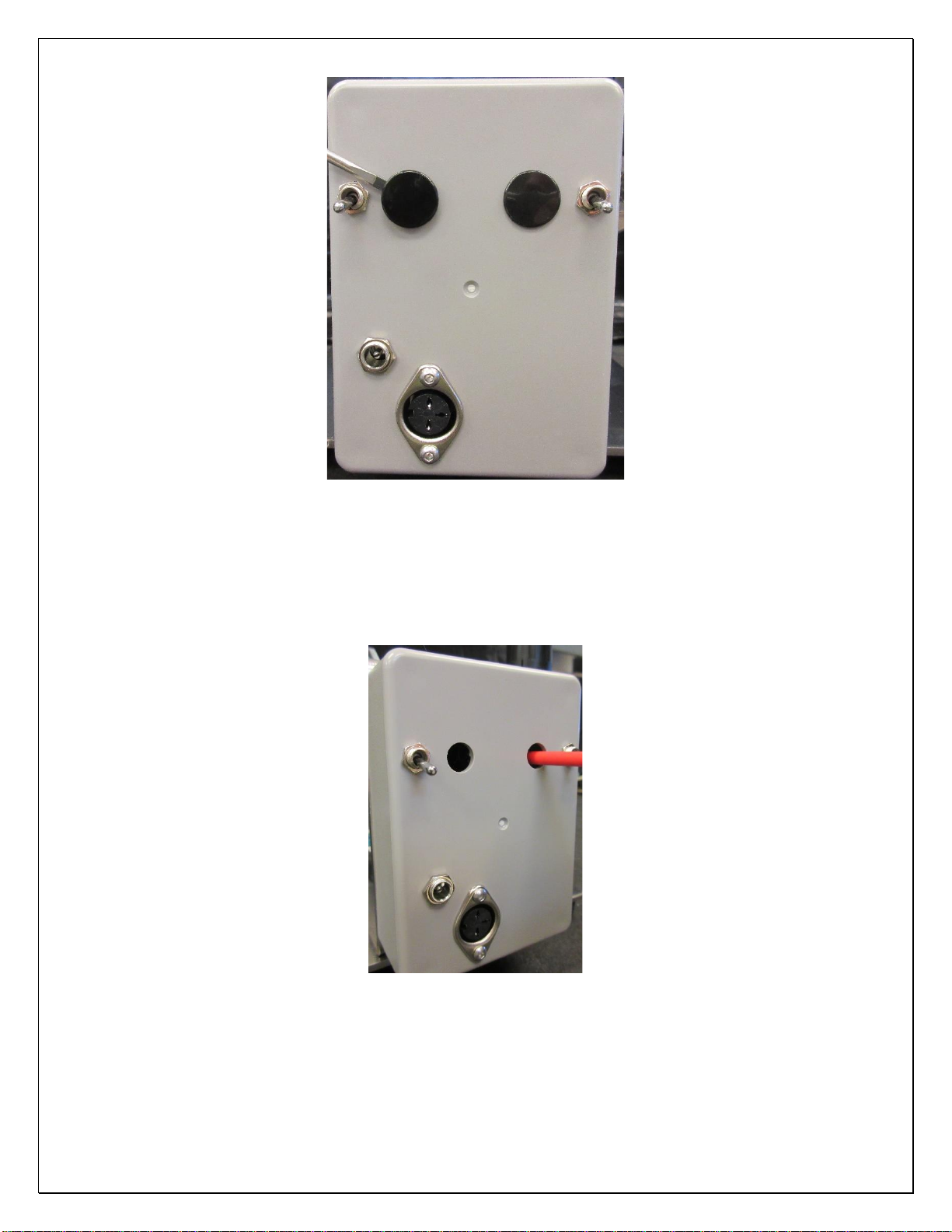
•With A/C power and compressed air attached to the expander, actuate the electric foot
switch which will activate the expander. Adjust the expander lower jaw to the position
you want using the Thumb Wheel Knob. Note that the jaws may be set to remain in the
“open” position using the toggle switch noted in Figure 3.3.1, and triggering the foot
pedal. Make sure the toggle switch is returned to the “off” position, or the jaws will
remain open.
•Turning the Thumb Wheel clockwise will increase the jaw expansion size, counter
clockwise will decrease the jaw expansion size. This adjustment may require fine tuning
depending on your tubing I.D., O.D., durometer and/or material.
•Once you have the expansion size you want tighten the Lock Nut to secure the
adjustment.
•Place the desired tubing over the ends of both expander jaws and hold firmly in place.
•Once the tube is placed over the jaw, the jaws will expand at a rate determined by the
expansion time setting. Note: The unit may be operated with an optional electric foot
switch as well.
•The jaws will then close and the operator will rotate the tubing 90 degrees. Failure to do
so may result in uneven expansion and/or damaged tubing!
•After the interval time has expired, the jaws will then perform their second expansion
operation, again at the appropriate expansion time.
•The jaws will then close a second time, and the machine cycle will be complete.
Note: Several expanding actions may be necessary to effectively expand the end of
the tube for the fitting/connector to slide in. Each time you expand the tubing
remember to rotate the tubing 90 degrees on the jaws.
•Quickly insert the component or tube connector before the tubing regains its original size.
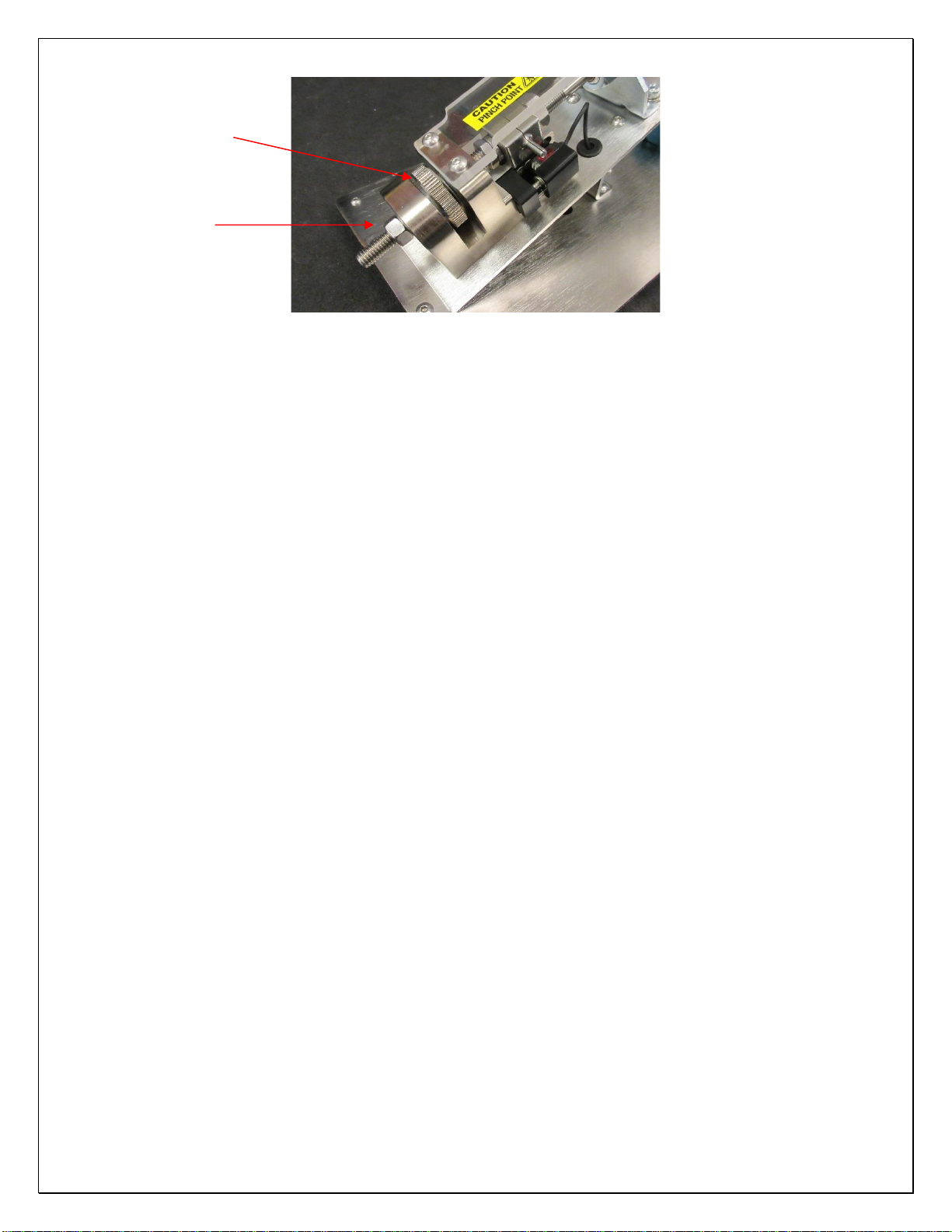
•If adjustment of sensor position is desired, use a 3mm hex wrench to turn the adjustment
screw shown below in figure 7. Turning the sensor adjustment screw clockwise will
move the sensor line closer to the jaws, while counterclockwise moves the sensor line
away from the jaws.

10
Figure 3.3.2: Sensor Adjustment Screw
•To operate the foot switch (optional), turn the switch on the rear cover to the down
position and plug the pedal into the foot switch jack. Note: The foot pedal will
operate the unit when it is plugged in, regardless of the switch position. Please
use caution.
3.4 Jaw installation and removal
•Tools required are: 3/8” open ended wrench, 9/16’ open ended wrench, 11/16” open
ended wrench, 3mm, 4mm and 3/32nd hex wrench
•Remove jaw guard by removing two 5x10mm screws using a 3mm hex wrench.
•Turn the thumb wheel clockwise until the cylinder shaft is fully extended in the jaw block
channel. Figure 3.4.1
Cylinder shaft shown fully extended and retracted in jaw block channel
Figure 3.4.1 –Fully extended Fully retracted
•Using a 1/2”open end wrench to hold the cylinder on the flats and a 3/4” open end
wrench break the upper jaw nut loose by turning counter clockwise. Figure 3.4.2.
Sensor Adjustment Screw

11
•Using a 9/16” open end wrench break the lower jaw nut loose while holding the thumb
wheel in place, keeping the threaded rod from rotating. Figure 3.4.3
Figure 3.4.2 Figure 3.4.3
•Now remove the two 6x12mm screws holding the front cylinder mount bracket using a
5mm hew wrench. Figure 3.3.4. Rotate the cylinder backwards until it stops in the semi-
vertical position. Figure 3.4.5
Remove two 6x12mm screws Cylinder semi-vertical position
Figure 3.4.4 Figure 3.4.5
•Rotate the upper jaw by hand counter clockwise until removed.
•Important note: when screwing upper jaw onto cylinder shaft it is important to only
screw the jaw at least 3/4 of the way on. This is to keep the upper jaw from slipping
off the jaw block when the cylinder is retracted, as well as allowing for the jam nut
to be tightened.

12
Figure 3.4.6: Jaw threaded 2/3-3/4 onto shaft Figure 3.4.7: Jaw threaded on too far and
has slipped off jaw block
•Using a 3mm hex wrench to turn the sensor adjustment screw, completely remove
sensor. Figure 3.4.8
•Next remove the two sensor bracket screws with a 2mm hex wrench and then remove
the sensor bracket. Figure 3.4.9
•When replacing the lower jaw do not loosen or tighten the jam nut on the
threaded rod while it is in the mounting block. It will damage the mounting
block.
•Remove the 3/8” hex nut (loosening with a 9/16” wrench, if necessary) and turning
Thumb Wheel until the threaded rod comes out of the mounting block.
•Loosen or tighten jam nut with the threaded rod removed. (Fig15) This can be best
accomplished by holding the back of the jaw in place with a 3/4" wrench and turning
the jam nut with a 9/16” wrench.
Figure 3.4.8: Remove Sensor Figure 3.4.9: Sensor bracket screws Figure 3.4.10: Threaded rod removed
•Select replacement jaw set and assemble them in the reverse order of operations.
•Note: If the cylinder shaft won’t retract when being cycled the adjustment of both
set screws on the front cylinder mount bracket will need to be adjusted. To make the
adjustment you must first loosen the two 6x12mm screws using a 5mm hex wrench

13
(Figure 3.4.11) and then by adjusting the two set screws using a 3/32nd hex wrench.
Figure 3.4.12. Now tighten the two 6x12mm screws and ensure jaw alignment.
6x12 mm screws (One per side) Set Screw (One per side)
Figure 3.4.11 Figure 3.4.12
4.0 Troubleshooting
Operating Error
Action
Unit does not operate.
1. Check the facility air connection.
2. Check all air hose connections and electrical
connections on the unit.
Jaws do not expand.
1. Ensure there are no obstructions keeping the
jaws from expanding.
2. Completely depress the foot pedal to actuate.
3. Ensure the toggle switch is set to the
appropriate setting (sensor or foot pedal)
Flexible tubing is splitting/tearing.
1. Ensure the tubing being expanded does not
exceed the recommended durometer.
2. Ensure the lower jaw has been adjusted
correctly for the tubing inside diameter (I.D.).
3. Verify facility air supply psi or unit pressure
adjustment.
4. Increase the expansion time setting for a more
gradual expansion.

14
5.0 Maintenance
5.1 Periodic Cleaning (annually)
•Wipe down outer surfaces with alcohol, septihol or mild detergents as required.
5.2 Tools List
•3/8”, 9/16” and 11/16” open ended wrenches.
•3/32”, 3mm and 4mm hex wrenches (T-handle preferred).
•Small standard screwdriver, #0 Phillips screwdriver
6.0 Product Specifications
Unit Weight
13.5 LBS / 6.1 KG
Overall Dimensions
15-1/4”l x 7”w x 7-1/2”h
Minimum Facility Air Supply
100 PSI
Unit Air Regulator Setting
80-120 PSI
7.0 Durometer Scale

15
8.0 Wiring Diagram
Note: Schematic drawings are provided for troubleshooting only—
not for modifying the machine in any way!

16
9.0 Warranty
9.1 Warranty
The manufacturer warrants the product manufactured by it, when properly installed, operated, applied and
maintained in accordance with the procedures and recommendations outlined in the manufacturer’s operation
manual, to be free from defects in material or workmanship for a period as specified below, provided such defect
is discovered and brought to the manufacturer’s attention within the stated warranty period.
The manufacturer will repair or replace any product or part determined to be defective by the manufacturer within
the warranty period, provided such defect occurred in the normal service and not as a result of misuse, abuse,
neglect or accident. Normal maintenance items requiring routine replacement are not warranted. The warranty
covers parts and labor for the warranty period unless otherwise specified. Repair or replacement shall be made at
the factory or the installation site, at the sole discretion of the manufacturer. Any service performed on the product
by anyone other than the manufacturer must first be authorized by the manufacturer.
Unauthorized service voids the warranty and any resulting charge or subsequent claim will not be paid. Products
repaired or replaced under warranty shall be warranted for the unexpired portion of the warranty applying to the
original product.
The foregoing is the exclusive remedy of any buyer of the manufacturer’s product. The maximum damages
liability for the manufacturer is the original purchase price of the product or part.
THE FOREGOING WARRANTY IS EXCLUSIVE AND IN LIEU OF ALL OTHER WARRANTIES,
WHETHER WRITTEN, ORAL, OR STATUTORY, AND IS EXPRESSLY IN LIEU OF THE IMPLIED
WARRANTY OF MERCHANTABILITY AND THE IMPLIED WARRANTY OF FITNESS FOR A
PARTICULAR PURPOSE. THE MANUFACTURER SHALL NOT BE LIABLE FOR LOSS OR DAMAGE BY
REASON OF STRICT LIABILITY IN TORT OR ITS NEGLIGENCE IN WHATEVER MANNER
INCLUDING DESIGN, MANUFACTURE OR INSPECTION OR THE EQUIPMENT OR ITS FAILURE TO
DISCOVER, REPORT, REPAIR, OR MODIFY LATENT DEFECTS INHERENT THEREIN.
THE MANUFACTURER, HIS REPRESENTATIVE OR DISTRIBUTOR SHALL NOT BE LIABLE FOR
LOSS OF USE OF THE PRODUCT OR OTHER INCIDENTAL OR CONSEQUENTIAL COSTS, EXPENSES,
OR DAMAGES INCURRED BY THE BUYER, WHETHER ARISING FROM BREACH OF WARRANTY,
NEGLIGENCE OR STRICT LIABILITY IN TORT.
The manufacturer does not warrant any product, part, material, component, or accessory manufactured by others
and sold or supplied in connection with the sale of manufacturer’s products.
9.1 Warranty Period
Parts and labor are for ninety (90) days from the date of shipment from the factory. Freight to the factory on units
that the manufacturer requests to be returned shall be paid by the purchaser, all return freight to be paid by the
manufacturer; means of transportation to be specified by the manufacturer.
For additional information contact: www.cleanroomdevices.com
Clean Room Devices, Inc.
10855 Dover Street, Suite 100
Westminster, CO 80021
303-438-0853
Table of contents
Other CLEAN ROOM DEVICES Industrial Equipment manuals