Clear-Com PS-704 User manual

PS-704 FOUR-CHANNEL POWER SUPPLY
INSTRUCTION MANUAL
CLEAR-COM ENCORE

PS-704 Four-Channel Power Supply Instruction Manual
© 2007 Vitec Group Communications Ltd. All rights reserved.
Part Number 810494Z Rev. 2
Vitec Group Communications, LLC.
850 Marina Village Parkway
Alameda, CA 94501
U.S.A
Vitec Group Communications
7400 Beach Drive
Cambridge Research Park
Cambridgeshire
United Kingdom
CB25 9TP
Vitec Group Communications
Room 1806, Hua Bin Building
No. 8 Yong An Dong Li
Jian Guo Men Wai Ave
Chao Yang District
Beijing, P.R. China 100022
® Clear-Com, CellCom/FreeSpeak and the Clear-Com Communication Systems logo are registered trademarks of The Vitec Group
plc.

PS-704 FOUR-CHANNEL POWER SUPPLY i
CONTENTS
OPERATION . . . . . . . . . . . . . . . . . . . . . . . . . . . . . . . . . . . . . . . 1-1
Introduction . . . . . . . . . . . . . . . . . . . . . . . . . . . . . . . . . . . . . . . . . . . . . . . . . 1-1
The Clear-Com Concept. . . . . . . . . . . . . . . . . . . . . . . . . . . . . . . . . . . . . . . . 1-1
Description . . . . . . . . . . . . . . . . . . . . . . . . . . . . . . . . . . . . . . . . . . . . . . . . . . 1-2
Fail Safe Power. . . . . . . . . . . . . . . . . . . . . . . . . . . . . . . . . . . . . . . . . . . . . . . . 1-2
PS-704 Overall Description. . . . . . . . . . . . . . . . . . . . . . . . . . . . . . . . . . . . . . 1-4
Front Panel . . . . . . . . . . . . . . . . . . . . . . . . . . . . . . . . . . . . . . . . . . . . . . . . 1-4
Rear Panel . . . . . . . . . . . . . . . . . . . . . . . . . . . . . . . . . . . . . . . . . . . . . . . . . 1-4
Power Distribution and Short Circuit Protection. . . . . . . . . . . . . . . . . . . . 1-5
Operation . . . . . . . . . . . . . . . . . . . . . . . . . . . . . . . . . . . . . . . . . . . . . . . . . . . 1-5
Front and Rear Panel Controls. . . . . . . . . . . . . . . . . . . . . . . . . . . . . . . . . . 1-5
Rear Panel Connectors. . . . . . . . . . . . . . . . . . . . . . . . . . . . . . . . . . . . . . . . 1-6
Front panel Indicators . . . . . . . . . . . . . . . . . . . . . . . . . . . . . . . . . . . . . . . . 1-6
To Check Before Powering System. . . . . . . . . . . . . . . . . . . . . . . . . . . . . . . . . 1-7
Check Termination . . . . . . . . . . . . . . . . . . . . . . . . . . . . . . . . . . . . . . . . . . 1-7
Check Intercom Cable Resistance . . . . . . . . . . . . . . . . . . . . . . . . . . . . . . . 1-7
Final Tests . . . . . . . . . . . . . . . . . . . . . . . . . . . . . . . . . . . . . . . . . . . . . . . . . 1-7
INSTALLATION. . . . . . . . . . . . . . . . . . . . . . . . . . . . . . . . . . . . . . 2-1
Quick Start . . . . . . . . . . . . . . . . . . . . . . . . . . . . . . . . . . . . . . . . . . . . . . . . . . 2-1
Installation . . . . . . . . . . . . . . . . . . . . . . . . . . . . . . . . . . . . . . . . . . . . . . . . . . 2-1
Intercom Line Connection . . . . . . . . . . . . . . . . . . . . . . . . . . . . . . . . . . . . 2-1
Line Termination (Rear Panel). . . . . . . . . . . . . . . . . . . . . . . . . . . . . . . . . . 2-2
Program Input (Rear Panel) . . . . . . . . . . . . . . . . . . . . . . . . . . . . . . . . . . . . 2-2
Rack Mounting . . . . . . . . . . . . . . . . . . . . . . . . . . . . . . . . . . . . . . . . . . . . . 2-2
Wiring. . . . . . . . . . . . . . . . . . . . . . . . . . . . . . . . . . . . . . . . . . . . . . . . . . . . . . 2-3
Single-Channel System . . . . . . . . . . . . . . . . . . . . . . . . . . . . . . . . . . . . . . . 2-3
Multi-Channel System. . . . . . . . . . . . . . . . . . . . . . . . . . . . . . . . . . . . . . . . 2-5
Crosstalk Considerations . . . . . . . . . . . . . . . . . . . . . . . . . . . . . . . . . . . . . . . . 2-6
Intercom Cable Considerations . . . . . . . . . . . . . . . . . . . . . . . . . . . . . . . . . . . 2-7
MAINTENANCE . . . . . . . . . . . . . . . . . . . . . . . . . . . . . . . . . . . . . 3-1
Introduction . . . . . . . . . . . . . . . . . . . . . . . . . . . . . . . . . . . . . . . . . . . . . . . . . 3-1
PS-704 Block Diagram . . . . . . . . . . . . . . . . . . . . . . . . . . . . . . . . . . . . . . . . . 3-1
Troubleshooting Tips. . . . . . . . . . . . . . . . . . . . . . . . . . . . . . . . . . . . . . . . . . . 3-2
TECHNICAL SPECIFICATIONS . . . . . . . . . . . . . . . . . . . . . . . . . . . . . . 4-1
PS-704 Four-Channel Power Supply . . . . . . . . . . . . . . . . . . . . . . . . . . . . . . . 4-1
GLOSSARY . . . . . . . . . . . . . . . . . . . . . . . . . . . . . . . . . . . . . . . . 5-1

PS-704 FOUR-CHANNEL POWER SUPPLY
ii
LIMITED WARRANTY . . . . . . . . . . . . . . . . . . . . . . . . . . . . . . . . . . . 6-I
Warranty Period. . . . . . . . . . . . . . . . . . . . . . . . . . . . . . . . . . . . . . . . . . . . . . . 6-i
Technical Support . . . . . . . . . . . . . . . . . . . . . . . . . . . . . . . . . . . . . . . . . . . . . 6-i
Warranty Repairs and Returns . . . . . . . . . . . . . . . . . . . . . . . . . . . . . . . . . . . . 6-ii
Non-Warranty Repairs and Returns. . . . . . . . . . . . . . . . . . . . . . . . . . . . . . . . 6-ii
Extended Warranty . . . . . . . . . . . . . . . . . . . . . . . . . . . . . . . . . . . . . . . . . . . . 6-ii
Service Contract . . . . . . . . . . . . . . . . . . . . . . . . . . . . . . . . . . . . . . . . . . . . . 6-iii
Liability. . . . . . . . . . . . . . . . . . . . . . . . . . . . . . . . . . . . . . . . . . . . . . . . . . . . 6-iii

PS-704 FOUR-CHANNEL POWER SUPPLY iii
IMPORTANT SAFETY INSTRUCTIONS
1. Read these instructions.
2. Keep these instructions.
3. Heed all warnings.
4. Follow all instructions.
5. Do not use this apparatus near water.
6. Clean only with dry cloth.
7. Do not block any ventilation openings. Install in accordance with the
manufacturer’s instructions.
8. Do not install near any heat sources such as radiators, heat registers, stoves,
or other apparatus (including amplifiers) that produce heat.
9. Do not defeat the safety purpose of the polarized or grounding-type plug. A
polarized plug has two blades, with one wider than the other. A
grounding-type plug has two blades and a third grounding prong. The wide
blade or the third prong are provided for your safety. If the provided plug
does not fit into your outlet, consult an electrician for replacement of the
obsolete outlet.
10. Protect the power cord from being walked on or pinched particularly at
plugs, convenience receptacles, and the point where they exit from the
apparatus.
11. Only use attachments/accessories specified by the manufacturer.
12. Use only with the cart, stand, tripod, bracket, or table specified by the
manufacturer, or sold with the apparatus. When a cart is used, use caution
when moving the cart/apparatus combination to avoid injury from tip-over.
13. Unplug this apparatus during lightning storms or when unused for long
periods of time.
14. Refer all servicing to qualified service personnel. Servicing is required when
the apparatus has been damaged in any way, such as power-supply cord or
plug is damaged, liquid has been spilled or objects have fallen into the
apparatus, the apparatus has been exposed to rain or moisture, does not
operate normally, or has been dropped.
15. WARNING: To reduce the risk of fire or electric shock, do not expose this
product to rain or moisture.
Please familiarize yourself with the safety symbols in Figure 1. When you see
these symbols on this product, they warn you of the potential danger of electric
shock if the main station is used improperly. They also refer you to important
operating and maintenance instructions in the manual.
Please read and follow these
instructions before operating
this product.
PS-704 FOUR-CHANNEL POWER SUPPLY
iv
Figure 1: Safety Symbols
EMC AND SAFETY
The PS-704 power supply meets all relevant CE, FCC, UL, and CSA
specifications set out below:
EN55103-1 Electromagnetic compatibility. Product family standard for audio,
video, audio-visual, and entertainment lighting control apparatus for
professional use. Part 1: Emissions.
EN55103-2 Electromagnetic compatibility. Product family standard for audio,
video, audio-visual, and entertainment lighting control apparatus for
professional use. Part 2: Immunity.
UL 60065-7, CAN/CSA-C22.2 No.60065-3, IEC 60065-7 Safety
requirements.
And thereby compliance with the requirement of Electromagnetic
Compatibility Directive 2004/108/EC and Low Voltage Directive 2006/95/EC
This device complies with Part 15 of the FCC Rules. Operation is subject to
the following two conditions: (1) this device may not cause harmful
interference, and (2) this device must accept any interference received,
including interference that may cause undesired operation.
CAUTION
RISK OF ELECTRIC SHOCK
DO NOT OPEN
This symbol alerts you to the presence of uninsulated dangerous
voltage within the product's enclosure that might be of sufficient
magnitude to constitute a risk of electric shock. Do not open
the product's case.
This symbol informs you that important operating and main-
tenance instructions are included in the literature accompanying
this product.

PS-704 FOUR-CHANNEL POWER SUPPLY 1-1
OPERATION
INTRODUCTION
Congratulations on choosing this Clear-Com product. Clear-Com was
established in 1968 and remains the market leader in providing intercoms for
entertainment, educational, broadcast and industrial applications. The
ruggedness and high build-quality of Clear-Com products defines the industry
standard. In fact, many of our original beltpacks and main stations are still in
daily use around the world.
The PS-704 power supply is a powerful, yet user-friendly unit that can serve as
the heart of a Clear-Com system. We recommend that you read through this
manual completely to better understand the function of the PS-704 and how to
optimize your system setup. Please pay particular attention to the section on
system wiring, as improper wiring detracts from the performance of the system
or causes system failure. If you encounter a situation or have a question that this
manual does not address, contact your dealer or call Clear-Com directly at the
factory. Our applications support and service people are standing by to assist you.
(Refer to Chapter 6: “Warranty” for contact information.) Thank you for
selecting Clear-Com for your communications needs.
THE CLEAR-COM CONCEPT
Clear-Com is a closed-circuit intercom system that consistently provides
high-clarity communication in both high-noise and low-noise environments. A
basic system consists of a single- or multi-channel power supply or main station
connected to various single- or multi-channel remote stations, such as beltpacks
and loudspeaker stations.
Clear-Com is a distributed amplifier system; each main and remote station
houses its own mic preamplifier, headset or speaker power amplifier, and
signaling circuitry. Stations bridge the intercom line at a very high impedance
and place a minimum load on the line. The audio level always remains constant,
and does not fluctuate as stations leave and join the system. Low-impedance mic
input lines and specially-designed circuitry make Clear-Com channels virtually
immune to RFI and dimmer noise.
Clear-Com stations are interconnected with two-conductor, shielded
microphone cable (or individually shielded multi-pair cable as required). Portable
stations are connected with two conductor cables with 3-pin XLR connectors.
One wire, connected to pin #2, carries the DC power from a main station or
power supply to all remote stations. The other wire, connected to pin #3, carries
the two-way (duplex) audio information. The shield, connected to pin #1, acts as
a common ground. One termination per channel is needed throughout the
intercom network, and is usually located in the main station or power supply.
1

PS-704 FOUR-CHANNEL POWER SUPPLY
1-2
Clear-Com main stations, power supplies and certain remote stations each have
an auxiliary program input with its own volume control, which allows an
external audio source to be fed to the intercom system.
Visual Signal Circuitry (call lights), a standard feature on all main and remote
stations, allows the user to attract the attention of operators who have removed
their headsets.
Clear-Com manufactures a wide variety of both portable and fixed-installation
units. All are compatible with each other. Clear-Com intercom systems can also
interface with other communication systems and devices.
DESCRIPTION
The Clear-Com PS-704 is a single rack space, one- to four-channel intercom
power supply which can provide up to 1.2 amperes per channel to operate
Clear-Com beltpacks and remote stations. This power is supplied to any or all of
four channels, and will support up to 40 beltpacks or 10 speaker stations.
Clear-Com’s new fail-safe design automatically shuts down the power to a
channel when a short circuit or electronic overload is sensed on that channel. The
other channels continue to operate normally. Once the fault condition is
removed, the PS-704's fail-safe circuit will bring the power back up, even under
full load conditions. LED indicators signal a fault on any channel. A line-level
program input offers a master input level. Individual program selects, each with
its own send level, are provided for each channel. Use of a switching power
supply allows the PS-704 to operate with any AC line voltage from 100 volts to
240 volts AC at 50 Hz or 60 Hz. The metal chassis and extra-thick front panel
with integral rack ears maintains legendary Clear-Com ruggedness.
FAIL SAFE POWER
An intercom power supply has special needs that are not met by traditionally
designed power supplies. An intercom power supply must work in adverse
conditions such as low AC line voltage, momentary shorts on the DC power
lines to the stations, and excessive peak loads during “power-on”conditions. The
following features are incorporated into the PS-704’s power supply:
•AUTOMATIC SHORT CIRCUIT PROTECTION: The PS-704’s
internal power supply checks each channel for a short or current overload. If
it detects a short the power supply will shut down that channel. A short
duration short circuit will not cause the power supply to interrupt power.
•AUTOMATIC OVERLOAD PROTECTION: The PS-704’s internal
power supply senses the difference between shorts and overloads. If an
overload is detected the power supply will shut down that channel. An
overload lasting a short period will not cause the power supply to interrupt
power.
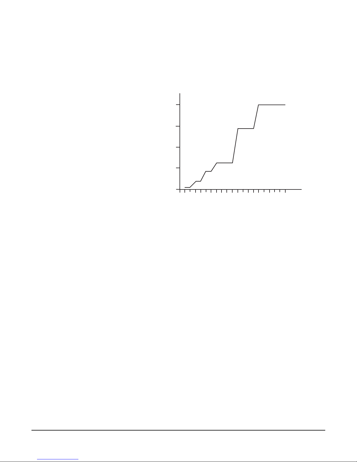
•AUTOMATIC POWER RESTORE: The PS-704’s internal power supply
senses the difference between short-term and long-term shorts and overload
conditions. After the first few times a short or overload occurs, the power
supply will try to restore power after only 0.5 seconds. If the short or
PS-704 FOUR-CHANNEL POWER SUPPLY 1-3
overload persists or occurs repeatedly, the power supply will take
progressively longer (to a maximum of 20 seconds) to try to restore power.
This protects the power supply from damage due to overheating. Once the
short is removed, the channel will recover, even under a full load condition.
The automatic power restore times are shown in the following chart:
Figure 1-1: Automatic Power Restore Times
•INDIVIDUAL CHANNEL SHORT CIRCUIT PROTECTION: Each
individual channel is separately overload and short circuit protected and may
draw as much as 1.2 amperes, though the total to both channels is limited to
2 amperes. A short on any one intercom line will not bring the whole system
down.
•FRONT PANEL INDICATIONS: There are four overload indicators on
the front panel (one for each channel) and a power indicator for the power
supply. The overload indicators light steady when an overload or short
condition is detected. They blink if power to a channel has been shut off as a
result of an overload or short.
•PARALLELING MULTIPLE POWER SUPPLIES: Multiple power
supplies can be paralleled to increase system capacity. The PS-704’s internal
power supply will automatically detect the actions of other power supplies
during overloads and short circuits to restore power as quickly as possible.
•MULTI-CHANNEL REMOTE STATIONS MAINTAIN THE POWER
LINE ISOLATION: The RM-704, RM-702 and KB-702 as well as any two
or four channel remote station or beltpacks are designed to use the isolated
power provided by the PS-704. Refer to Chapter 2‚ “Installation.”
•LOW NOISE CIRCUITRY: The direct current outputs of the PS-704
contain very little hum and noise. The PS-704 does not contribute to
audible noise in the remote stations and beltpacks.
Note: Power supply lines connected together at remote stations will disable the
individual channel short circuit protection feature.
12345678910 11 12 13 14 15 16 17 18 19 20
5
10
15
20
0
0
0.5
2
4
7
14
20
Number of
seconds to
restore
Number of recent shorts or overloads

PS-704 FOUR-CHANNEL POWER SUPPLY
1-4
PS-704 OVERALL DESCRIPTION
A brief description of the connectors and controls follows. (Refer to Figure 1-2.)
Figure 1-2: Front and Back Panels of PS-704
FRONT PANEL
1. POWER SWITCH: Switches the AC power to the PS-704 on and off. The
adjacent green LED will illuminate when the power is on.
2. OVERLOAD INDICATORS: The respective red LED for each channel (A,
B, C, D) will illuminate if the PS-704 senses a short or overload on that
channel. When the fault is removed, the PS-704 will automatically reset and
the LED will go out.
3. PROGRAM SEND: Slide switch on each channel (A, B, C, D) selects that
channel to receive the program input coming into the PS-704. All channels
receive the same signal from the rear panel program input.
4. PROGRAM SEND LEVEL: Trimpot adjusts the audio level of the program
sent to its respective channel.
REAR PANEL
5. PROGRAM INPUT: Female 3-pin XLR jack accepts a balanced or
unbalanced line-level input.
6. PROGRAM INPUT LEVEL: Adjusts the program level coming into the
PS-704. Used with the program send level controls to achieve desired system
program levels.
7. TERM. ON/OFF: Slide switch (one per channel) selects whether the
PS-704 will provide termination for that channel. The default position is on.
8. INTERCOM LINE CONNECTOR: There are two 3-pin male XLR
connectors per channel, wired in parallel or “looped-through.”
9. AC POWER SUPPLY INPUT: Connects to AC with an IEC cable. The
PS-704’s power supply will accept any line voltage between 100 volts and
240 volts AC @ 50 Hz - 60 Hz. It will automatically adjust to the line
voltage. There is no need for a selector switch or an external fuse.
Send
Level
Overload
Program
OnOff
Channel A
Power
PS-704
Send
Level
Overload
Program
OnOff
Channel B
Send
Level
Overload
Program
OnOff
Channel C
Send
Level
Overload
Program
On
Off
Channel D
PROGRAM INPUT
LEVEL
ADJUST
CHANNEL D
TERM
D
ON
OFF
CHANNEL C
TERM
C
ON
OFF
CHANNEL B
TERM
B
ON
OFF
CHANNEL A
TERM
A
ON
OFF
PS-704
1
2
34
5
89 7
4-Channel
Power Supply
6
Output: 30V, 1.2A Continuous, 2A Peak

PS-704 FOUR-CHANNEL POWER SUPPLY 1-5
Note: Power supply lines connected together at remote stations will disable the
individual channel short circuit protection feature.
POWER DISTRIBUTION AND SHORT CIRCUIT PROTECTION
Depending upon how many shorts or overloads a channel has experienced
recently, the PS-704 will attempt to turn power on again within 0.5 to 20
seconds of automatically cutting off power to an overloaded channel. This allows
momentary short or overload conditions to clear automatically. If the PS-704
cuts power off to one or more channels, it will indicate which channel is affected
by blinking the red overload light(s) corresponding to these channel(s). This light
will assist in locating the shorted or overloaded channel. Shorts are generally
caused by miswiring or damaged cables. Overloads are generally caused by
connecting too many beltpacks and stations to a channel.
The current requirements of Clear-Com remote stations and beltpacks vary with
model and use. A station that is simply on and idling in the circuit may draw only
a small amount of current.
The PS-704 provides DC power to operate Clear-Com beltpacks and remote
stations. The power is distributed between the four channels and will support
up to 40 RS-601 beltpacks or 10 speaker stations or 12 headset stations.
OPERATION
Because the PS-704 is a power supply, its actual operation is very straightforward.
Some forethought as to system layout, station selection, and cabling schemes is
worthwhile, especially if the system encompasses multiple channels, a large
number of stations, long cable runs or any combination of these. The only actual
user-initiated operation of the PS-704 once it is connected to the system is to
switch the power on, check and set the terminations, select the program sends,
and adjust the levels. Any time the system is initially powered up, it is a good idea
to verify that none of the overload indicator LEDs are lit.
FRONT AND REAR PANEL CONTROLS
In the following descriptions, the numbers in the left column refer to Figure 1-2
on page 1-4.
1POWER SWITCH: Switches the AC power to the PS-704 on and off. When
in the on position, the LED indicator to the left of the switch should
illuminate. Check the short indicators for evidence of system malfunctions.
3PROGRAM SEND ON/OFF: These toggle switches, one for each channel,
connect program audio to that channel. The number of active sends will not
affect the overall send level to any channel.
4PROGRAM SEND LEVEL: These potentiometers, or trim pots (one for
each channel), adjust the level of program heard in that channel. The
program switch must be on for the control to function on that channel. (The
level controls work in conjunction with the program in [6] level control on
the rear panel.) For a higher program level, turn the control clockwise. For

PS-704 FOUR-CHANNEL POWER SUPPLY
1-6
less program level, turn the control counter-clockwise. If the control is all the
way up on a channel and the program level in the line is not loud enough,
increase the input level with the program in control on the rear panel.
Conversely, if there is still program heard on a channel when its level is all
the way down, decrease the program in level. Any change in the program in
level control on the rear panel to adjust for one channel will necessitate
adjustment on the other channels to compensate.
6PROGRAM INPUT LEVEL ADJUSTMENT (rear panel): Use this trim
pot to adjust the overall input level of the external program. Turn the control
clockwise to increase the gain and counter-clockwise to reduce it.
Note: Do not force the trim pots past their stop points as this will damage
them.
7TERM ON/OFF: These toggle switches activate the termination for their
respective channel when switched to on. These should always be on unless
there are other power supplies or terminated main stations in the system. If
there are other possible terminations in the system, it must be decided where
each channel’s single termination will be.
REAR PANEL CONNECTORS
5PROGRAM INPUT: This 3-pin female XLR jack accepts a balanced or
unbalanced line-level signal. This is typically a feed from an audio board, an
air feed from a studio to remote site over a phone line, or an audio cue track.
Send levels to the individual channels are controlled with a combination of
the program in level and the program send levels on the channels.
8INTERCOM LINE CONNECTOR: There are two 3-pin male XLR jacks
per channel, wired in parallel, or looped through. All the stations in the
system are ultimately connected to the station through these jacks. Because
intercom audio is two-way, they are neither inputs nor outputs, but may be
thought of as “ports.” Pin #1 is connected to the shield and carries the signal
ground. Pin #2 carries the DC voltage that runs the remote stations. Pin #3
carries two-way audio and call signals.
FRONT PANEL INDICATORS
2OVERLOAD INDICATORS: If a short-circuit condition appears on any of
the four intercom lines, the sense circuitry for that line will disconnect the
DC power to that line only and the red LED for that channel will be on. If a
red LED is illuminated, the fault on that channel must be located and
removed. The overload LED will go out and the PS-704’s automatic short
reset circuitry will automatically bring the power back up on that channel
when the fault is removed. If there are no shorts, but the LED stays on, an
overload exists, possibly due to too many intercom stations connected on
that intercom line.
If the failure continues, unplug the intercom line connected to the affected
channel. Its red short LED should go out. This indicates a short in that line.
Follow that intercom line connecting and disconnecting cables along the line
until the fault is isolated.

PS-704 FOUR-CHANNEL POWER SUPPLY 1-7
TO CHECK BEFORE POWERING SYSTEM
Before you turn on the power:
CHECK TERMINATION
There should be one and only one termination for each channel in the system.
This termination is usually set to on at the main station or power supply. To
ascertain that only one termination is present on the channel, perform the
following test:
1. Using a multimeter, measure the resistance between pins #1 and #3 on one
of the channel A XLR connectors at the rear of the unit.
2. If the channel is terminated properly, then the resistance should measure
approximately 4 K
Ω
.
A very high channel resistance means the channel is not
terminated. Channel resistance of 2 K
Ω
indicates a double-termination. If a
double-termination is indicated, locate the other power supply or main
station and set its termination to off.
Note: The location of the termination switch varies with model. On some
products, the termination switches are on the rear panel; on others,
they are inside the unit. Consult the unit’s manual for the location.
3. Repeat for the other channels.
4. Check resistance between chassis ground and pin #1. Using an Ohmmeter,
measure the resistance from pin #1 on the main station or power supply to
chassis ground. The measurement should read 10
Ω
.
A high reading (over
100
Ω
) indicates that the 10
Ω
resistor in the unit has failed and requires
replacement. Failure to perform the replacement will result in an audible
“buzz” in the system. A reading of less than 10
Ω
(or a short) typically
indicates that the shell and pin #1 of one of the interconnect cables are
shorted together. Test the individual cables until the culprit is located and
repair or replace the cable.
Caution: Pin #1 and the shell of the XLR plug on the interconnect cables
should NOT be connected together.
CHECK INTERCOM CABLE RESISTANCE
For minimal crosstalk, the ground resistance of the intercom cables should be as
low as possible, preferably less than 2
Ω
.
Disconnect an intercom line from the
main station or power supply. At the point in the intercom line furthest from the
unit, connect a clip lead jumper between pins #1 and #2. Back at the “powered”
end, use an Ohmmeter to measure the resistance between pins #1 and #2. A
value of less than 4
Ω
is ideal.
FINAL TESTS
After you turn the power on:
1. Check for proper voltage on pin #2 of any intercom line or jack in a channel.
It should read 26 to 30 volts.

PS-704 FOUR-CHANNEL POWER SUPPLY
1-8
2. Test for proper operation of call signaling. Activate the call signal on any belt
pack or station. The call lights on all other stations on that channel should
illuminate and then go out when the call button is released.
3. Adjust the sidetone null on all stations. (Refer to the manual for each specific
unit for instructions.)

PS-704 FOUR-CHANNEL POWER SUPPLY 2-1
INSTALLATION
QUICK START
1. Unpack the unit and inspect for any damage that may have occurred during
shipping.
2. Connect the proper AC mains cable.
3. Install the PS-704.
4. Connect the AC to the mains circuit. Connect the intercom lines and
program input as required.
5. Set the four termination switches on the rear panel to on.
6. Switch power on. The green power light should be on and the four red short
lights should be off.
7. Select program sends and set program levels as required using program input
level adjust and program send level. Program level controls on unused
channels should be set to the fully counterclockwise position.
8. Set levels and sidetone nulls at remote stations.
9. The intercom system should now be operating properly.
10. Read the rest of this manual for further information.
INSTALLATION
Choose the location of the PS-704. The unit requires access to AC power. It
should be located away from other equipment that generates excessive amounts
of heat. The choice of location will also depend upon the wiring scheme (refer to
the section “Wiring”).
INTERCOM LINE CONNECTION
The PS-704 provides two rear-panel 3-pin male XLR connectors for each
intercom line. These connectors are wired in parallel and intended for
loop-through connection. Any single-channel station or channel of a
multi-channel station connected on a line plugged into Channel A of the PS-704
will be “party-lined” with all the other stations on that same channel. In a
multi-channel system, the goal is to assign specific people to the correct group
(i.e. the other people with whom they need to be in contact the most). This is
particularly important when the party line users are on a single-channel beltpack
or station; less so if they are on multi-channel stations. The pinout of the
intercom connectors is as follows:
Pin #1 --- Ground (shield)
Pin #2 --- Power
Pin #3 --- Audio
2

PS-704 FOUR-CHANNEL POWER SUPPLY
2-2
LINE TERMINATION (REAR PANEL)
Switching of the channels’ terminations on and off are done with the rear-panel
toggle switches. In most systems, all terminations on the PS-704 should be in the
on position (default setting). The fundamental concept of Clear-Com party-line
intercom is that all channels are terminated in one location, preferably at the
power supply.
Caution: All intercom lines must be terminated. Care must be taken not to
“double-terminate” a line. All unused intercom lines must also be
terminated.
The PS-704 provides terminations for each of its four channels. Clear-Com main
stations and power supplies provide switch-selectable termination networks on all
intercom lines. It is up to the user to ensure that the terminations are set
correctly. An unterminated line will cause excessive levels, possible oscillation of
line drivers, and severe imbalance of hybrid null networks. A line with double or
multiple terminations will cause low levels and severe imbalance of hybrid null
circuits.
If the PS-704 is the only power supply in the system (no other power supplies or
powered main stations are in the system) the termination switch on each channel
of the PS-704 should be switched to on. Simply toggle the rear-panel switch
labeled term to the on position. The termination switch should be set to the off
position only if the channel is terminated at another station.
PROGRAM INPUT (REAR PANEL)
A 3-pin XLR female connector provides the main program input to the station.
This input level is controlled by the rear-panel program level control adjacent to
the program in connector. This control sets the overall level for all the channels.
The input accepts a balanced or unbalanced line-level audio signal. The program
can be fed to any or all of the intercom lines by using the front-panel toggle
switches labeled program on/off. There is one of these switches for each channel.
The pinout of the program input connector is as follows:
Pin #1 --- Ground (shield)
Pin #2 --- + Signal
Pin #3 --- - Signal
RACK MOUNTING
The unit requires 1.75 in. (44 mm or 1RU) of rack space. It requires no
additional free rack space above or below it for ventilation. The station is 7.5 in.
(165 mm) in depth and requires at least 2.5 in. (64 mm) clearance in the rear for
connectors and cables. The single-piece front panel has integral “rack ears.” This
adds stability and strength.
PS-704 FOUR-CHANNEL POWER SUPPLY 2-3
WIRING
When considering how to wire an intercom system, several factors must be taken
into account. These include the number of stations, the length of the cable runs
and whether single or multiple channels are preferred. If multi-channel stations
are connected with multi-pair cables, then crosstalk becomes an important issue.
(Crosstalk is not a factor with single-channel systems or multi-channel systems
where each channel is run on its own individual cable to single-channel remote
stations.) While the physical considerations include ease of installation, type of
cabling, station location, etc., the electrical considerations are concerned
primarily with the capacitance between conductors on the intercom line and the
DC resistance in the ground return of the intercom line.
Caution: Pin #1 and the shell of the XLR plug on the interconnect cables should
NOT be connected together.
Excessive resistance in the conductors of the cable results in a loss of sidetone null
at remote stations and some overall loss of level. Excessive resistance in the
ground connector or shield greatly increases crosstalk between channels. This can
greatly affect the performance of multi-channel systems.
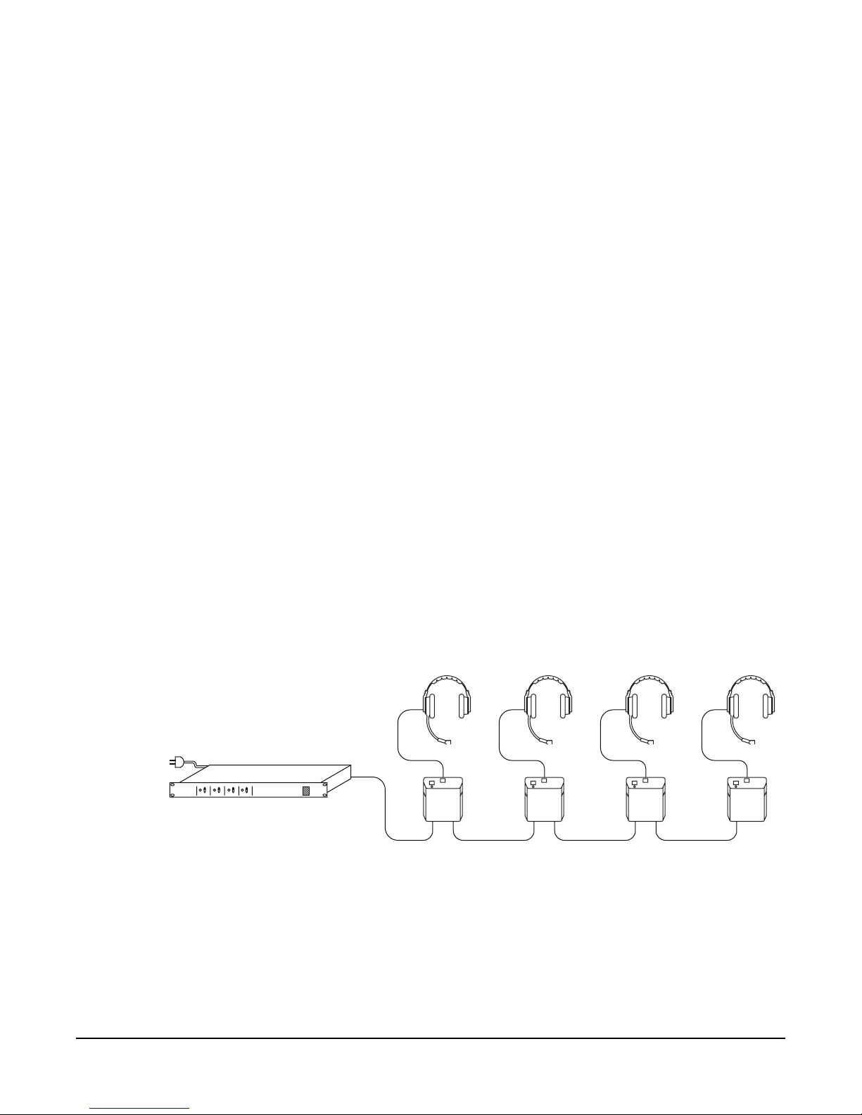
SINGLE-CHANNEL SYSTEM
In a single-channel system, there are two general methods of wiring remote
stations to the power supply. Any one method may be used exclusively in a small
system and both may be used in various combinations for a larger system.
1. Daisy Chain: Remote stations are wired from one station to the next and so
on along each line connected to the power supply. This requires the least
amount of cable, but may be impractical due to the system layout. Also, if a
break occurs in the line, all stations downline of the break will be
disconnected from the party line.
Figure 2-1: Daisy Chain
PS-704
PS-704 FOUR-CHANNEL POWER SUPPLY
2-4
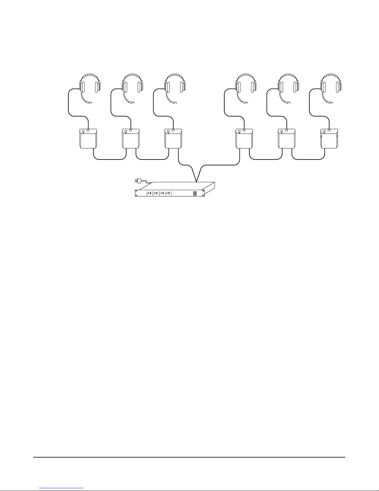
2. Hub or Star: Each remote station is wired directly back to the power supply
or to a split line wired directly to the power supply.
Figure 2-2: Hub or Star
Channel AChannel A
PS-704

PS-704 FOUR-CHANNEL POWER SUPPLY 2-5
MULTI-CHANNEL SYSTEM
In a multi-channel system where each channel is run on its own cable and
connected only to single-channel remote stations as in the following diagram,
there are no crosstalk issues because the channels do not share a common ground.
Consult the table “Belden Shielded Cables” in the next section for cable
recommendations.
Figure 2-3: Multi-channel System
In a multi-channel system where multiple channels are run from the PS-704 to
multiple channel stations as in the following diagram, crosstalk can be an issue.
This is because the channels will share a common ground at both ends of the
cable run. If this kind of connection will be used, refer to the section “Crosstalk
Considerations.”
Figure 2-4: Multi-channel to multi-channel
Channel A
Channel BChannel C
Channel D
PS-704
Channel A
Channel B
Channel C
Channel D
Channel A
Channel B
Channel C
Channel D
GndGnd
PS-704 4 C hannel R emote S tation
to other
Remote
Stations
PS-704 FOUR-CHANNEL POWER SUPPLY
2-6
CROSSTALK CONSIDERATIONS
When multiple channels are fed to remote stations, the amount of crosstalk
between channels is proportional to the DC resistance of the ground return path
back to the channel terminations. To minimize this crosstalk between channels
when running more than one channel in a multi-pair cable, keep the DC
resistance of the ground return as low as possible. Ideally, this should be less than
2
Ω
.
This can be achieved as follows:
• Keep cable runs under 500 ft. (152.5 m).
• Use a cable whose common shield has a low DC resistance.
• Connect unused cable wires of a multi-pair cable to the pin #1 shield.
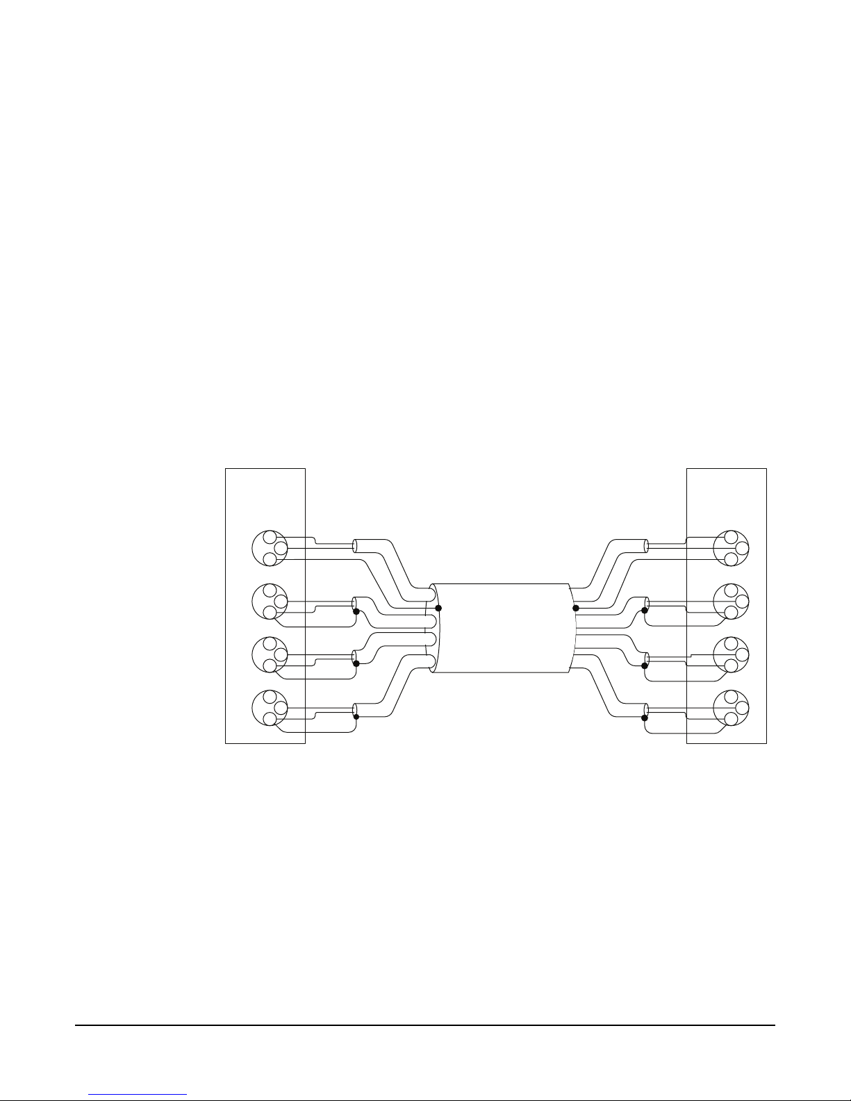
If shielded multi-pair cables are used to connect multiple channels between the
PS-704 and remote stations, the cables should be wired to maximize the number
of ground connectors to minimize crosstalk. In the following cable wiring
diagram, note that it is not necessary to run redundant power connectors on each
channel to the remote station. The spare wires which would normally conduct
power are instead used to augment the drain wire ground connection.
Figure 2-5: PS-704 to 4-Channel Remote Station
Note: All multi-pair cables must have individually shielded pairs.
Clear-Com recommends the Belden 1800 series of multi-pair cables. They offer a
common shield with a low DC resistance in addition to individual shields on
each pair.
Typical system performance for a Clear-Com system is contingent on the use of
Clear-Com or Clear-Com approved compatible headsets. Use of headsets other
than these can induce crosstalk into a multi-channel system through the headset
cable. Clear-Com does not recommend the use of headset extension cables or
headset “Y” cables, as they will increase crosstalk into a multi-channel system.
2
3
1
PS-704
Power
Supply
A
B
C
D
2
3
1
2
3
1
2
3
1
2
3
1
4-Channel
Remote
Station
A
B
C
D
2
3
1
2
3
1
2
3
1
Power
Ch. A Audio
Ch. D Audio
Ch. B Audio
Ch. C Audio
Gnd*
Gnd*
Gnd*
* = S pa re W ire used for G nd
Drain wire G nd
Ch. D Audio
Gnd*
Ch. C Audio
Ch. B Audio
Gnd*
Gnd*
Ch. A Audio
Power
Drain wire Gnd
** = If the s hields from individual
pairs a re brought out s eparate ly,
they must alsobe connected to
Pin 1.
S hield**
S hield**
S hield**
S hield**
S hield**
S hield**
Table of contents
Other Clear-Com Power Supply manuals


Popular Power Supply manuals by other brands


Scientech Technologies
Scientech Technologies Scientech 4077A Product tutorial

National Instruments
National Instruments NI PS-15 user manual

Celestron
Celestron POWER TANK 18774 instruction manual

SFC Energy
SFC Energy EFOY Pro Series Hints & Tips

ABB
ABB 4234 600 instruction manual

Keysight
Keysight E3632A Service guide


