Clear Water OzoneMax OZ-SPA User manual
Vacuum-ultraviolet Ozone Systems
TM
OzoneMAX
3
Model
OZ-SPA
Installation
&
Operation Manual

2
A. Important Safety Instructions
IMPORTANT SAFETY INSTRUCTIONS
When using this electrical equipment, basic safety precautions
should always be followed, including the following:
READ AND FOLLOW ALL INSTRUCTIONS
in this manual before attempting installation.
• A wire connector is provided on this unit to connect a minimum 12 AWG solid copper conductor between this unit and
any metal equipment, metal enclosures of electrical equipment, metal water pipe, or conduit within five (5) feet (1.5m)
of the unit.
• Follow all applicable electric codes.
• All permanent electrical connections should be performed by a qualified electrician.
• For cord and plug connected units:
“Risk of electric shock. Connect only to properly grounded, grounding type receptacle.”
• For cord and plug connected units:
“Do not bury cord.”
• For cord and plug connected units:
“Warning – To reduce the risk of electric shock, replace damaged cord immediately.”
• If electrically connecting this unit directly to pool controls, ensure the controls are protected by a (G.F.C.I.) Ground Fault
Circuit Interrupter.
• Install at least five (5) feet from wall of pool water using nonmetallic plumbing. Install ozone generator no less than one
(1) foot above the maximum water level to prevent water from contacting electrical equipment.
Install in accordance with the installation instructions.
• Mount the unit so that it is not accessible by anyone in the pool.
• Electric Shock Hazard. Disconnect unit from power source before attempting service.
• WARNING: Short term inhalation of high concentrations of ozone and long term inhalation of low concentrations of
ozone can cause serious harmful physiological effects. Do not inhale ozone gas produced by this device.
• WARNING: UV Light is harmful to eyes and exposed skin. Do not look directly at the Ozone producing bulb used in
this device.
B. Identifying OzoneMAX components
OZ-SPA
Power Box
OZ-VIK
Venturi Injection Kit
Owners
Manual
Warranty
Card
Indicator
Light
Output
Connector
4 Piece Molly Set
with #10 Screws

3
C. Tools & Materials Required
D. Site Survey
The OZ-SPA system is comprised of a power box and a venturi injection kit , which needs to be
installed at the very end of the return line (after the filter, ionizer electrode chamber, heater, etc.).
The ozone unit will need to be installed to a post or wall within six (6) feet of a 115 or 220VAC timer,
electrical box or a 115V receptacle. This location will need to be within six (6) feet of location of the
venturi injector. This location should be mounted at least one (1) foot above maximum water level
and preferably out of direct sunlight. The ozone unit should be no closer than five (5) feet from a
body of water.
• Bullet Level • Drill & Drill Bits
• Hacksaw or Pipe Cutter • PVC Cement
• PVC Cleaner/Primer • Utility Knife
• Screwdrivers, Flat & Phillips • Screws & Anchors
within 6 feet within 6 feet
Power Source/
TimerBox
OZ-SPA Unit Venturi Injector
E. Installing the Power Box
Mount the OZ-SPA unit to a post or wall using the four mounting screw holes in the enclosure base.
The unit may be mounted horizontally or vertically, however it is recommended that the vent holes not
face upward and be directly exposed to rainfall. The location of the box must be within six (6) feet of
the location of the venturi, which is plumbed on the return line. The unit should be mounted at least
one (1) foot above maximum water level and preferably out of direct sunlight. The power box should
also be located no closer than five (5) feet from a body of water.

4
F. Electrical
Any electrical connections should be performed by a certified electrician in accordance with all
electrical codes. OZ-SPA systems are universal voltage, meaning the unit will work on 115 or
230VAC without any internal switching. When locating the power source, make sure that when the
pump and motor shuts off, the OZ-SPA will too. The ideal source is the timer box. If no timer box
exists, the unit can use the pump motor as its power source. In other words, the electrical connection
should be such that the OZ-SPA is supplied power only when the power is supplied to the pool
filter/circulation pump.
A permanent ground bonding connector is provided on this unit and should
be used to connect a minimum 12 AWG solid copper wire conductor to any
metal equipment, metal enclosures of electrical equipment, metal water pipe,
or conduit within five (5) feet of the unit.
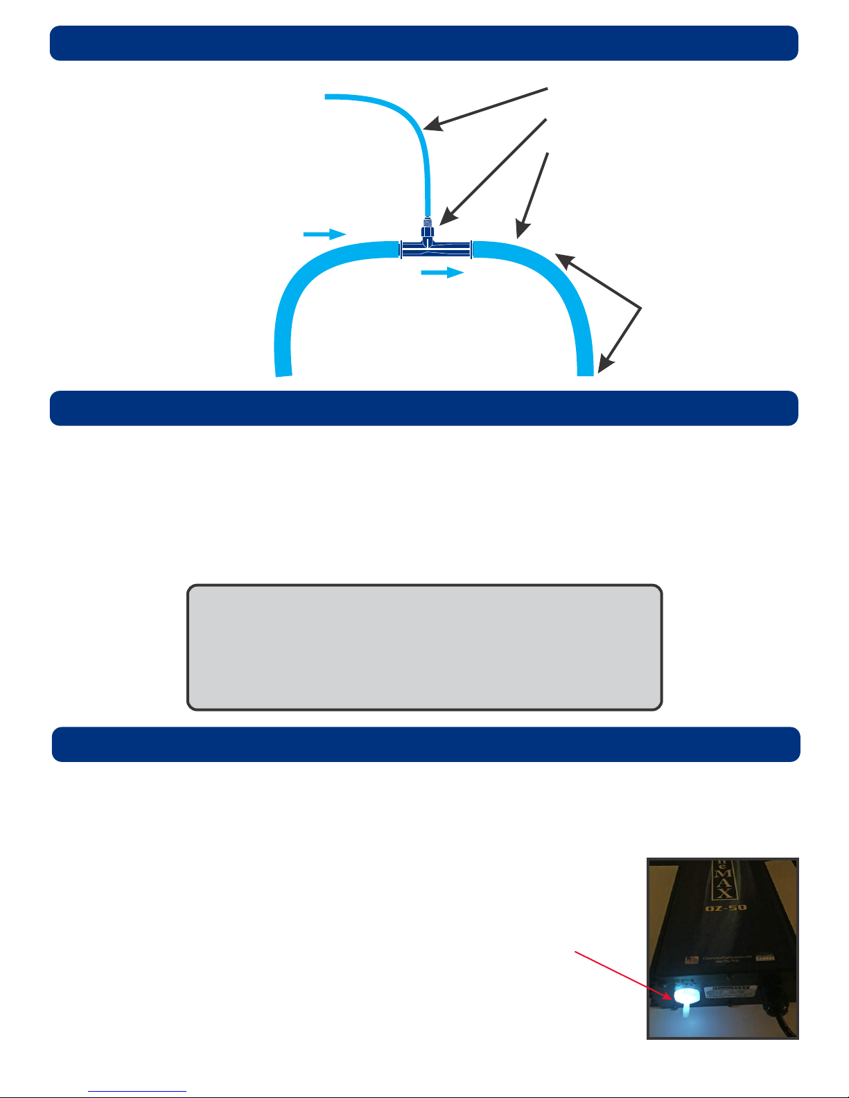
G. Installing the Venturi Injector
Using the above drawing, install the venturi injector kit (OZ-VIK) as seen on page 6
Continue on next page >>>
Pump
SPA
Filter Heater
Power Source/
Pump Timer
Kynar check valve
¼” reinforced vinyl hose
Venturi Injector
¾” mpt to ¾” barbed adapter
¾” ID vinyl tubing
2” slip x ¾” fpt x 2” slip tee
water flow
water flow
N = Nylon Hose Clamps
M = Metal Hose Clamps
N
MM
MM
N
N

5
G. Installing the Venturi Injector (continued)
MAKE SURE THE WATER FLOWS IN THE DIRECTION OF THE ARROW ON THE VENTURI INJECTOR
AND TO INSTALL IT IN THE CORRECT DIRECTION OF THE WATER FLOW.
The installation of the Kynar check valve is a precautionary one we require during installation in case of the
unlikely failure of the venturi that is built in the manifold. This would prevent water from entering the
OzoneMAX unit. To make sure this is properly installed, cut a few inches of the reinforced hose and insert one
end on the outlet coming out of the OzoneMAX unit. Install the check valve, then connect the other end of the
remaining piece of hose to the check valve and then to the venturi injector – which is located on the manifold.
It is important that you install the Kynar check valve where air flow is allowed toward the injector. Air direction
can be tested by blowing into the ¼” I.D. polybraid tubing. If correctly installed, you will see air bubbles enter
the ¾” I.D. clear vinyl tubing.
DO NOT SUCK ON THE ¼” I.D. TUBING WHEN CONNECTED TO THE OZONE SYSTEM.
After installation and turning on all the equipment, you will see a frothing (very tiny milk-like bubbles) action
immediately after the venturi injector. This is located on the ¼” clear vinyl hose. These tiny bubbles should
also appear at the nearest return line and possibly other return lines. This means ozone is getting injected into
the pool’s water.
OZ-VIK - Venturi Injection Kit
G
H
H
I
J
K
L
M
N
O
G. (1) Mazzei venturi injector
H. (2) 2” slip x ¾” fpt x 2” slip tee
I. (4) ¼” nylon hose clamps
J. (4) 1 ¼” metal hose clamps
K. (1) ¼”x ¼” Kynar check valve
L. (1) 8' of ¾” ID vinyl tubing
M. (2) ¾” mpt to ¾” barbed adapter
N. (9) ¼”x 14” long zip ties
O. (1) 8' of ¼” reinforced vinyl hose
6
I. Balancing the Spas Water
Spa Water Chemistry
To achieve optimal performance from the OZ-SPA system, it is recommended the following be
performed prior to initial start-up:
• BACKWASH or clean filter
• Test and adjust water chemical balance to recommendations in the chart below
pH . . . . . . . . . . . . . . . . . . . . . . . . . . . . . 7.2 - 7.6
Total Alkalinity (TA) . . . . . . . . . . . . . . . 80 - 120 ppm
Calcium Hardness (CH) . . . . . . . . . . . . 150 - 350 ppm
Total Dissolved Solids (TDS). . . . . . . . 300 - 2000 ppm
Copper Ion Levels . . . . . . . . . . . . . . . . 0.15 - 0.2 ppm
J. Periodic Inspection
The amazing thing you will notice about the OZ-SPA system is the clarity of the water, especially if
you are using the MineralPURE ionization system in conjunction with it.
You might initially notice the water getting cloudy the first couple of days. DO NOT BE ALARMED.
THIS IS NORMAL! You will want to clean or backwash your filter after the first
week.
Visual Inspection
You will want to periodically inspect the power box in the evening to ensure the
unit is functioned correctly. Turn the system on temporarily, if needed. The
indicator light, located next to the output connector will glow a nice blue color.
The ozone unit should only be on when the pump is running.
To insure that the venturi injector and bypass are working correctly, simply
observe to see if small bubbles are entering the pool and the “frothing” effect is
taking place in the clear window of the venturi manifold window.
Continue on next page >>>
H. Starting the System
“Frothing”
Effect
(small bubbles)
¼” reinforced vinyl hose
Venturi Injector
¾” ID vinyl tubing
(this side should be
showing very
small bubbles)
water flow
water flow
Once everything has been
connected, turn on the power
to the OZ-SPA unit. Make sure
all the connections are
complete and tight.
After installation and turning on
all the equipment, you will see
a frothing (very tiny milk-like
bubbles) action immediately
after the venturi injector. This is
located on the ¼” clear vinyl
hose. These tiny bubbles
should also appear at the
nearest return line and possibly
other return lines. This means
ozone is getting injected into
the pool’s water.

7
K. Scheduled Maintenance & Replacing the UV Bulb
There is very little maintenance required with the OZ-SPA unit, however we do recommend you
replace the ozone hoses and check valves once a year.
Replace ozone hose once a year
Order replacement part – OZ-HOSEKIT –
from your dealer. This complete package includes 8 feet of hose, two check
valves, 6 hose clamps, and 5 zip ties.
Replacing the UV Bulb
Order replacement part – OZ-10L –
Replacement Aqua Elite 10 bulb – from your dealer.
Replace the UV bulb after approximately 9,000 hours of use. This is approximately 12 years of running the
ozone unit 2 hours a day, 365 days a year. We recommend the bulb gets changed at about 70% of its life for
optimum performance, or the 9,000 hours. To determine the actual number of hours the ozone system has
been running, simply calculate the number of days your spa is open a year by the number of hours per day the
equipment is running. When the bulb does lose its power, you will notice the water getting cloudier quicker or
having to use more chlorine than usual. You can also check the clear connector on the output tube of the
power box. It should be a glowing blue in color if the bulb is on. Note: It is much easier to view this indicator
feature in the evening hours when there is no bright sunlight.
When replacing the UV bulb, we strongly recommend you remove the unit from the wall. This is to insure you
carefully remove the delicate equipment from the metal enclosure properly, and seal back up tightly.
Replacing the bulb in the OZ-SPA unit.
1. Disconnect power from the OZ-SPA unit. Coming into contact of the exposed ozone bulb can
cause serious damage to your health.
2. Remove the six (6) screws on the bottom of the unit.
Continue on next page >>>
J. Periodic Inspection (continued)
Periodically check the unit intake vent holes for the unlikely event of debris accumulation. It is
important these vent holes are open for air to enter the ozone unit. Do not look directly into the vent
holes when the UV bulb is operating.
Plumbing Issues
Minor adjustment of the ball valve (when installing the manifold) may be required to divert water
through the injector. This may be true with two speed or variable speed pumps. Older versions of
these adjustable speed pumps do not adjust well and you will need to adjust the ball valve to
accommodate flow through the venturi on low speed.
There is an internal check valve in the venturi injector. In the unlikely event this area becomes
clogged, it may be cleaned by removing the nut/barb and a retaining rubber seal. Care should be
used not to lose the internal ball and spring while taking the rubber seal off. Clean and reinstall.
Carefully replace bulb in white
connector and metal bracket
Bottom of unit with
bottom panel off
Metal plate with the bulb
ballast attached to it
Zip tie holding in bulb Cut zip tie
holding in bulb
Carefully remove bulb from
metal bracket & white connector

K. Scheduled Maintenance & Replacing the UV Bulb (continued)
3. Carefully pull off the bottom panel and slide out the metal plate with the UV bulb and ballast
attached to it as far as it will go – approximately 4 inches. There is a tether holding it in place so it
will not completely disconnect from the ozone box. Be careful NOT to pull out any wires.
4. Cut the zip tie holding the bulb in the bulb clamp. Be careful NOT to break the bulb.
5. Carefully pull the bulb from the white connectors and the bulb clamp from holding them in place
and remove. Be careful NOT to break the bulb. Dispose of bulb properly after removal.
6. Snap new bulb in place. Secure with the metal brackets.
7. Push metal plate back into its place inside the unit. There is no need to add another zip tie as this
was used for shipping purposes.
8. Replace the bottom plate, making sure the gasket is seated in the groves properly.
9. Tighten the 6 screws back into place, securing the bottom plate tightly.
10. Reconnect power. Make sure the bulb indicator (the clear connector on the output tube of the
power box) glows in a blue color. Again, you may want to check this in the evening hours out of
direct sunlight.
L. Warranty Information
This unit comes with a 1-year warranty to be free from defects in material and workmanship under
normal use from the date of purchase. See warranty card (blue card) included.
Sustainable solutions for our future
Manufactured by
Phone: 727-562-5186 • Toll Free: 800-756-SWIM (7946)
ClearwaterPoolSystems.com
TM
OzoneMAX
3
Vacuum-ultraviolet Ozone System
The Healthy Alternative to Chlorine
Designed, engineered
& assembled in the USA.
3/17
Table of contents
Other Clear Water Lighting Equipment manuals


