Bartec Wireless X BPXWXU1 User manual

User Manual
English
BPXWXU1, revision 4

2
Preface
Terms and Conditions ................................................................................................3
Introduction
Intro ..............................................................................................................................4
Product overview ........................................................................................................5
Specications and marking........................................................................................6
Product models...........................................................................................................7
Installation
Item check list..............................................................................................................8
Preparations for cabling and termination ...............................................................9
Fiber version (FIB) .....................................................................................................10
Power over ethernet version (POE) ........................................................................12
Ethernet and Power version (ETH)..........................................................................14
Power version (PWR) ................................................................................................16
Earthing......................................................................................................................17
Daisy chain congurations (DSY) ............................................................................18
Fiber daisy chain (FIB-DSY).......................................................................................18
Power daisy chain (PWR/ETH-DSY)
.....................................................................................................................................19
Preparations before installing.................................................................................20
Ceiling bracket...........................................................................................................21
Wall bracket...............................................................................................................22
Pipe bracket (Horizontal) .........................................................................................23
Pipe bracket (Vertical)...............................................................................................24
Mounting the Wireless X ..........................................................................................26
Maintenance
Inspection & Maintenance.......................................................................................28
Cleaning .....................................................................................................................28
Troubleshooting
FAQ .............................................................................................................................29
Troubleshooting........................................................................................................30
Repair .........................................................................................................................30
Support ......................................................................................................................30
Drawings and components
Technical drawings ...................................................................................................31
Material List ...............................................................................................................32
Declarations and certicates
Letter of Conformity.................................................................................................33
Compliance................................................................................................................33
CONTENTS
PREFACE
1.
3.
4.
5.
6.
7.
2.
Contents
3
TERMS AND CONDITIONS
Prefase
GENERAL TERMS AND CONDITIONS
Please nd the general terms and conditions at:
https://www.bartec.de/en/terms/TERMS_BARTEC_Group.pdf
WARRANTY SERVICE OPTIONS
Before contacting BARTEC PIXAVI, please try the following options:
1. Access https://www.pixavi.com/support-forum/ and our FAQ page for troubleshooting advice
and directions on running hardware diagnostics.
2. Consult the user manual which is included in your order. If you need additional assistance,
please use one of the following support options to contact BARTEC or our authorized BARTEC
Sales oces.
3. Online, chat and other forms of remote support may be available. Contact information is
available at https://www.pixavi.com/support-forum/
4. Telephone support requests: Please contact your local BARTEC Sales Oce.

4
INTRO
The Wireless X is nothing short of a revolution within wireless equipment in hazardous areas.
Based on 15 years of experience within wireless equipment and hazardous areas,
BARTEC PIXAVI has re-designed the bulky enclosure completely. We designed the smallest,
lightest and highest performing solution for wireless equipment ever created for hazardous
areas. Based on both clever engineering, material science and state of the art wireless
infrastructure, we are now eliminating the need for bulky and heavy enclosures and antennas.
The Wireless X is designed to meet the requirements for the harsh environments of the open
seas and is also ideal for onshore Petrochemical and Marine applications as well for all kind of
industry where an explosive atmosphere may be present.
Introduction
INTRODUCTION

5
Wireless device
Media converter *
* Conguration dependent
Power supply *
RF transparent dome
PRODUCT OVERVIEW
Input/output glands
Input/output
Ex d bushing *
Input/output
Ex d bushing *
Bracket for earthing
and locking
Ex e
enclosure
Ex d
enclosure
Termination
interface *
Ex e gasket
Introduction

6
SPECIFICATIONS AND MARKING
Specications:
Size Ø x H = 452.5 x 188
Weight 10 kg for Aluminum version *
Main materials • Marine grade aluminium and stainless steel
• Dome: RF transparent composite with gelcoat
Ambient
temperature
-20 ºC ≤ Tamb ≤ 60 °C *
Type of protection Ex d, e
Power Spec 85 - 264 VAC (47-63 Hz), 120 - 370 VDC, Max.10 A*
Packaging 510x510x310mm, 15kg *
Introduction
Marking:
Marking label
Document ID:
Wireless X
Silver
Alu
+/- 0,05mm
04
+47 92 26 92 64
14.12.2017
Andreas G. Mysen
A4
BPX_WX_ALL_IECEx_Atex_Marking BPXWXM1
DESCRIPTION:
Laser engraved lable
UNLESS OTHERWISE SPESIFIED:
SCALE: 1:5
FILE NAME:
SURFACE/COLOR:
DIMENSIONS ARE
IN MILLIMETERS
DO NOT SCALE DRAWING
COPYRIGHT AND MODIFICATION RIGHT RESERVED
PIXAVI AS, NORWAY
CONSTRUCTION UNDERLAY:
MUST BE CHEKED AND APPROVED BEFORE PRODUCTION
REVISION:
WWW.PIXAVI.COM
FINISH:
WEIGHT (g):
MATERIAL:
DRAWN BY:
DATE:
PROJECT:
NA
SHEET 1 OF 1
DEBUR AND BREAK
SHARP EDGES
OVERALL TOLERANCE:
PART ID:
+47 40 20 17 04
Placement of the marking on the product
WARNING:
POTENTIAL ELECTROSTATIC CHARGING HAZARD
– SEE INSTRUCTIONS
IECEx and Atex marking Read only version
Type:
Wireless radio enclosure
Ex db eb IIC T6 Gb
-20 ºC ≤ Tamb ≤ 60 °C
Serial nr:
PXWXEXYYSSSSSS
Presafe 17 ATEX 11333 X
IECEx PRE 17.0059 X
Mfr: BARTEC GmbH
97980 Bad Mergentheim, DE
85-264 VAC (47-63 Hz), 120-370 VDC
Max. 10 A
t
e
x
t
r
e
s
e
r
v
e
d
f
o
r
m
a
r
k
i
n
g
i
n
f
o
r
m
a
t
i
o
n
II 2G
II 2G
0044
E
x
d
b
e
b
I
I
C
T
6
G
b
-
2
0
º
C
≤
T
a
m
b
≤
6
0
°
C
P
r
e
s
a
f
e
1
7
A
T
E
X
1
1
3
3
3
X
I
E
C
E
x
P
R
E
1
7
.
0
0
5
9
X
S
e
r
i
a
l
N
r
:
B
P
X
W
X
E
X
Y
Y
S
S
S
S
S
S
T
y
p
e
:
W
i
r
e
l
e
s
s
r
a
d
i
o
e
n
c
l
o
s
u
r
e
M
f
r
:
B
A
R
T
E
C
G
m
b
H
9
7
9
8
0
B
a
d
M
e
r
g
e
n
t
h
e
i
m
,
D
E
8
5
-
2
6
4
V
A
C
(
4
7
-
6
3
H
z
)
,
1
2
0
-
3
7
0
V
D
C
,
M
a
x
.
1
0
A
0044
Serial number format is Serial: BPXWXEXYYSSSSSS
Where BPX=Manufacturer, WX=Wireless X, EX=Ex version
YY=Year of manufacture (17,18 and so on),
SSSSSS= unique serial number
(000001, 000002, 000003 and so on)
t
e
x
t
r
e
s
e
r
v
e
d
f
o
r
m
a
r
k
i
n
g
i
n
f
o
r
m
a
t
i
o
n
t
e
x
t
r
e
s
e
r
v
e
d
f
o
r
m
a
r
k
i
n
g
i
n
f
o
r
m
a
t
i
o
n
t
e
x
t
r
e
s
e
r
v
e
d
f
o
r
m
a
r
k
i
n
g
i
n
f
o
r
m
a
t
i
o
n
t
e
x
t
r
e
s
e
r
v
e
d
f
o
r
m
a
r
k
i
n
g
i
n
f
o
r
m
a
t
i
o
n
t
e
x
t
r
e
s
e
r
v
e
d
f
o
r
m
a
r
k
i
n
g
i
n
f
o
r
m
a
t
i
o
n
t
e
x
t
r
e
s
e
r
v
e
d
f
o
r
m
a
r
k
i
n
g
i
n
f
o
r
m
a
t
i
o
n
t
e
x
t
r
e
s
e
r
v
e
d
f
o
r
m
a
r
k
i
n
g
i
n
f
o
r
m
a
t
i
o
n
t
e
x
t
r
e
s
e
r
v
e
d
f
o
r
m
a
r
k
i
n
g
i
n
f
o
r
m
a
t
i
o
n
t
e
x
t
r
e
s
e
r
v
e
d
f
o
r
m
a
r
k
i
n
g
i
n
f
o
r
m
a
t
i
o
n
t
e
x
t
r
e
s
e
r
v
e
d
f
o
r
m
a
r
k
i
n
g
i
n
f
o
r
m
a
t
i
o
n
t
e
x
t
r
e
s
e
r
v
e
d
f
o
r
m
a
r
k
i
n
g
i
n
f
o
r
m
a
t
i
o
n
t
e
x
t
r
e
s
e
r
v
e
d
f
o
r
m
a
r
k
i
n
g
i
n
f
o
r
m
a
t
i
o
n
t
e
x
t
r
e
s
e
r
v
e
d
f
o
r
m
a
r
k
i
n
g
i
n
f
o
r
m
a
t
i
o
n
t
e
x
t
r
e
s
e
r
v
e
d
f
o
r
m
a
r
k
i
n
g
i
n
f
o
r
m
a
t
i
o
n
t
e
x
t
r
e
s
e
r
v
e
d
f
o
r
m
a
r
k
i
n
g
i
n
f
o
r
m
a
t
i
o
n
t
e
x
t
r
e
s
e
r
v
e
d
f
o
r
m
a
r
k
i
n
g
i
n
f
o
r
m
a
t
i
o
n
t
e
x
t
r
e
s
e
r
v
e
d
f
o
r
m
a
r
k
i
n
g
i
n
f
o
r
m
a
t
i
o
n
t
e
x
t
r
e
s
e
r
v
e
d
f
o
r
m
a
r
k
i
n
g
i
n
f
o
r
m
a
t
i
o
n
t
e
x
t
r
e
s
e
r
v
e
d
f
o
r
m
a
r
k
i
n
g
i
n
f
o
r
m
a
t
i
o
n
t
e
x
t
r
e
s
e
r
v
e
d
f
o
r
m
a
r
k
i
n
g
i
n
f
o
r
m
a
t
i
o
n
t
e
x
t
r
e
s
e
r
v
e
d
f
o
r
m
a
r
k
i
n
g
i
n
f
o
r
m
a
t
i
o
n
t
e
x
t
r
e
s
e
r
v
e
d
f
o
r
m
a
r
k
i
n
g
i
n
f
o
r
m
a
t
i
o
n
t
e
x
t
r
e
s
e
r
v
e
d
f
o
r
m
a
r
k
i
n
g
i
n
f
o
r
m
a
t
i
o
n
P
O
T
E
N
T
I
A
L
E
L
E
C
T
R
O
S
T
A
T
I
C
C
H
A
R
G
I
N
G
H
A
Z
A
R
D
W
A
R
N
I
N
G
:
-
S
E
E
I
N
S
T
R
U
C
T
I
O
N
S
Markings Explained
Wireless radio
enclosure
Product type
Ex db eb IIC
T6 Gb
Ex = Denotes explosive atmosphere
db = Protection concept
eb = Protection concept
IIC = Sub group
T6 = Temperature group
Gb = Equipment protection level
-20 ºC ≤ Tamb
≤ 60 °C
Ambient temperature rating
II 2G II = Equipment group
2 = ATEX category
G = Gas
CE 0044 CE marking and notied body number
Serial Nr BPX=Manufacturer
WX=Wireless X
EX=Ex version
YY=Year of manufacture
SSSSSS= unique serial number
Presafe 17
ATEX 11333 X
ATEX certicate number
IECEx PRE
17.0059 X
IECEx certicate number
Mfr Identies the manufacturer name and
address
Voltage, Amps Maximum voltage and Amps rating
* Depending on conguration and access point inside

7
PRODUCT MODELS
BPX-WX-**-***-***-***/...
ID number for main material:
AL: Aluminum chassis
ID number for cert rating:
Zn1: Zone 1 version
Zn2: Zone 2 version
ID number for configuration:
FIB: Fiber cable and power cable
ETH: Ethernet cable and power cable
POE: Ethernet cable with POE
PWR: Power cable
ID numbers for internal hardware
Does not influence explosion protection
ID number for additional cable options
STN: No additional option
DSY: Daisy chain
Introduction
Special Conditions for Safe Use:
“X” - The instruction indicates all the necessary information to ensure the
installation and use minimize the risk from electrostatic discharge.
“X” - Equipment must only be placed in areas with low risk of mechanical
danger (ref clause 26.4.2 in EN 60079-0).
“X” – The equipment is intended for installation only in certain position (see “Preparations
before installing”).

8
i
ITEM CHECK LIST
Before starting installation, check that all the following items have been included with your
Wireless X. If anything is missing, contact your dealer. Do not use any sharp objects like scissors
or knives when opening the box. This may damage the content.
Wireless X
Mounting bracket
User manual
Mounting hardware
Mounting xture
Wireless X enclosure
Stainless steel mounting
bracket
Printed user manual
1x safety wire
4x M6 fasteners for locking
Wireless X to the mounting
bracket
Used as stable support when
working in the Ex e chamber
INSTALLATION
Installation

9
Never perform any installation or maintenance work on the Wireless X while
it is connected to power!
Only use suitable M20x1.5 Atex or IECEx certied compression or barrier
glands depending on the cable/installation. Make sure a suitable material/
quality is selected to avoid galvanic corrosion with the main aluminum body.
Stainless steel is recommended.
Selection, Installation, Maintenance and repair of electrical apparatus for use
in potentially explosive atmosphere should be done in accordance with IEC/
EN 60079-14/ -17/ -19 . Product installation must be carried out in accordance
with any local codes that may apply and should only be carried out by a com-
petent electrical personnel.
The Wireless X has four dierent versions:
The next section contains guides for how to install and terminate the cables.
Fiber (FIB)
page 10
Power over ethernet (POE)
page 12
Ethernet and power (ETH)
page 14
Power (PWR)
page 16
Make sure to use cable ferrules on all cables when terminating.
Make sure the earth cable is min. 0.75mm2.
PREPARATIONS FOR CABLING AND TERMINATION
Installation

10
1. Remove Ex e lid and
insert cables into glands
Unscrew the 7 M6x1 fasteners
and remove the Ex e lid to
access the power and network
interfaces.
Follow the mounting instructions
of the cable glands thoroughly.
2.
3.
Unscrew the cover protecting
the ber splice tray and also
the smaller cover over the slot
you plan to splice the ber
cable in.
Preparing the ber
splice tray
Identify the RX and TX cables
(marked with a sticker) Make
sure to splice accordingly.
Prepare the ber - Strip the
protective coatings, jackets,
tubes, strength members, etc.
leaving only the bare ber
showing. Make sure that ber
surface area is clean.
Splicing ber
Always pay attention to the ber cables’ minimum bend radius of 30 mm.
If you bend the ber cable tighter than this minimum bend radius, you risk
breaking the ber cable.
FIBER VERSION (FIB)
Follow the cabling and termination instructions below for correct installation. Lay out the parts,
cables and components as shown in the illustrations. It's recommended to use the included
dome xture during the cabling and termination process.
Installation

11
Installation
4.
5.
Once properly aligned,
the fusion splicer uses an
electrical arc to melt the
bers, permanently welding
the two ber ends together.
Splicing ber
A typical fusion splice has a
tensile strength of between
0.5 and 1.5 lbs. Using heat
shrink tubing, silicone gel
and/or mechanical crimp
protectors will keep the
splice protected from outside
elements and breakage.
Protection of the splice
6.
7. Connect power and
ground
Verify that the incoming
powercable is NOT live using a
multimeter.
Add cable ferrules. Connect power
and ground cables to the power
and earth terminals. For additional
earthing info, see page: 17
Mount ber tray lid
Mount the small cover
protecting the splice, and then
the lid, protecting the entire
ber tray.

12
Installation
2.
Position the Ethernet cable
towards the termination block.
Positioning the Ethernet
cable
POWER OVER ETHERNET VERSION (POE)
8. Mount Ex e lid
Place the protective lid over
the Ex e chamber. Make sure
the Ex e gasket is properly
seated. Attach the 7 M6
fasteners. It is recommended
to use low- to medium
strength thread locking
sealant on all the 7 fasteners
1. Remove Ex e lid and
insert cables into glands
Unscrew the 7 M6x1 fasteners
and remove the Ex e lid to
access the power and network
interfaces.
Follow the mounting instructions
of the cable glands thoroughly.
Follow the cabling and termination instructions below for correct installation. Lay out the parts,
cables and components as shown in the illustrations. It's recommended to use the included
dome xture during the cabling and termination process.

13
InstallationInstallation
3.
4.
Cut cable insulation and
ethernet shielding according
to the illustrated values and
add cable ferrules.
Place the Ethernet cable shield
in contact with the shield
clamp.
Cable Insulation cutting
Attach the individual leads
to the termination block. The
connection points are spring
loaded. Important: Follow
the color coding indicated in
the illustration to the right.
Terminate Ethernet
cable
5.
6.
Add cable ferrules. Connect
ground cable to the earth
terminal. For additional
earthing info, see page: 17.
Place the protective lid over
the Ex e chamber. Make sure
the Ex e gasket is properly
seated. Attach the 7 M6
fasteners. It is recommended
to use low- to medium
strength thread locking
sealant on all the 7 fasteners.
Earthing
Mount Ex e lid
45 mm
35 mm
30 mm

14
Installation
2.
Position the Ethernet cable
towards the termination block.
Cable Positioning
ETHERNET AND POWER VERSION (ETH)
1. Remove Ex e lid and
insert cables into glands
Unscrew the 7 M6x1 fasteners
and remove the Ex e lid to
access the power and network
interfaces.
Follow the mounting instructions
of the cable glands thoroughly.
3.
Cut cable insulation and
ethernet shielding according to
the illustrated values and add
cable ferrules.
Place the Ethernet cable shield in
contact with the shield clamp.
Cable Insulation cutting
Follow the cabling and termination instructions below for correct installation. Lay out the parts,
cables and components as shown in the illustrations. It's recommended to use the included
dome xture during the cabling and termination process.
45 mm
35 mm
30 mm

15
InstallationInstallation
4.
Attach the individual leads
to the termination block. The
connection points are spring
loaded. Important: Follow
the color coding indicated in
the illustration to the right.
Terminate Ethernet
cable
6. Mount Ex e lid
5. Connect power and
ground
Verify that the incoming power
cable is NOT live using a
multimeter.
Add cable ferrules. Connect power
and ground cables to the power
and earth terminals. For additional
earthing info, see page: 17.
Place the protective lid over
the Ex e chamber. Make sure
the Ex e gasket is properly
seated. Attach the 7 M6
fasteners. It is recommended
to use low- to medium
strength thread locking
sealant on all the 7 fasteners.

16
Installation
2.
Position the power and
ground cables. Add cable
ferrules at the end of the
cables.
Cable Positioning
POWER VERSION (PWR)
1. Remove Ex e lid and
insert cables into glands
Unscrew the 7 M6x1 fasteners
and remove the Ex e lid to
access the power and network
interfaces.
Follow the mounting instructions
of the cable glands thoroughly.
3.
Verify that the incoming
power cable is NOT live using
a multimeter.
Connect power and ground
cables to the power and earth
terminals. For additional
earthing info, see page: 17.
Terminate cables
Follow the cabling and termination instructions below for correct installation. Lay out the parts,
cables and components as shown in the illustrations. It's recommended to use the included
dome xture during the cabling and termination process.

EARTHING
EARTHING: The Wireless X must be earthed to the earth system using
minimum one of the earth/xing points. This must be done according to the
requirements specied in IEC 60079-14.
+47 40 20 17 04
NA
PART ID:
SHEET 1 OF 1
DATE:
DRAWN BY:
WWW.PIXAVI.COM
REVISION:
COPYRIGHT AND MODIFICATION RIGHT RESERVED
PIXAVI AS, NORWAY
DO NOT SCALE DRAWING
DIMENSIONS ARE
IN MILLIMETERS
PART NAME:
SCALE: 1:10
UNLESS OTHERWISE SPESIFIED:
Wireless X earthing illustra�on
DESCRIPTION:
BPX_WX_ALL_Earthing_Illustration
A3
Andreas G. Mysen
07-Nov-17
+47 92 26 92 64
01
External earth
(4 possible locations )
provided and installed by customer
- Minimum 4mm2 cable
- M6 ring terminal
- M6 stainless steel locking washer
- M6 x1.0 stainless steel screw
- Minimum 0.75mm2 cable
- Wire ferrules
earth
termination
pre-installed
Internal earth through gland
provided and installed
by customer
17
InstallationInstallation
4.
Place the protective lid over
the Ex e chamber. Make sure
the Ex e gasket is properly
seated. Attach the 7 M6
fasteners. It is recommended
to use low- to medium
strength thread locking
sealant on all the 7 fasteners.
Mount Ex e lid

18
DAISY CHAIN CONFIGURATIONS (DSY)
Some versions can be congured as daisy chains, by having an extra output gland:
This section contain guidelines for how to install and terminate the cables.
Fiber daisy chain (FIB-DSY) Power daisy chain (PWR/ETH-DSY)
2.
Position the ber cable in the
ber splice tray and feed it out
of the gland.
Positioning the ber
cable
FIBER DAISY CHAIN (FIB-DSY)
1. Overview
Make sure the ber and power
are terminated as explained in
"FIBER VERSION (FIB)". Insert an
extra gland for the daisy chain
output.
The ber cables can be congured as a daisy chain, if you have an extra set of ber cables or
more coming inside the Ex e chamber. Please follow the cabling and termination instructions
below
Installation

19
Make sure the CC of the power cables are in the range of 1.5mm2to 4mm2
2.
Terminate the cables as
illustrated. Make sure to use
cable ferrules.
Termination
POWER DAISY CHAIN (PWR/ETH-DSY)
1. Overview
Make sure the power cables
are terminated as explained
in "POWER VERSION (PWR)"
or "ETHERNET AND POWER
VERSION(ETH)" Insert an extra
gland for the daisy chain output.
The power/ground cables can be congured as a daisy chain. Please follow the cabling and
termination instructions below
Installation

Never perform any installation or maintenance work on the Wireless X while
it is connected to power!
Only mount the Wireless X bracket to suitable structures.
The Wireless X must be mounted with the dome facing downwards.
Please follow deployment and guidelines provided by the wireless device
manufacturer when deploying the wireless equipment.
During installation, if working at height cannot be avoided, a risk assessment
should be carried out before any work at height is undertaken. The assess-
ment should highlight the measures that must be taken to ensure people are
not at risk of falling from height.
PREPARATIONS BEFORE INSTALLING
General info:
• It’s recommended to do a site survey to determine the best location to install the Wireless X.
• Optimal installation height is dependent on access point/model. Please check the
manufacturer specication.
The Wireless X can be mounted in three dierent basic congurations:
The following section contains guidelines for installing the mounting brackets in the three
dierent congurations, as well as, a guide on how to mount the Wireless X to the mounting
brackets.
Ceiling
bracket included
Pipe (horizontal/vertical)
BPX-AC-PIPE (accessory)
Wall
BPX-AC-WALL (accessory)
20
Installation
Table of contents
Other Bartec Enclosure manuals

Bartec
Bartec FEAM ESA Series User manual

Bartec
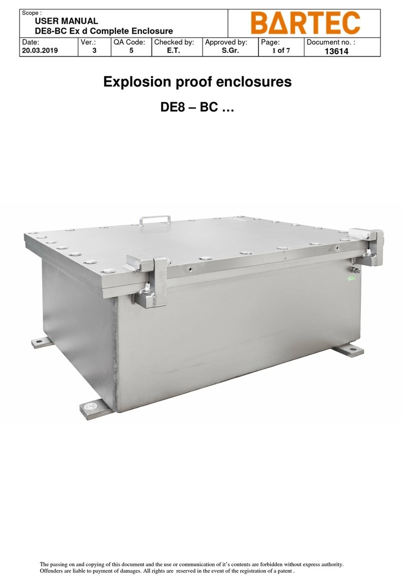
Bartec DE8-BC User manual

Bartec
Bartec GWR Series User manual

Bartec
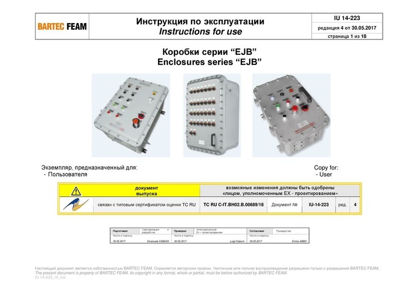
Bartec EJB Series User manual

Bartec
Bartec GWR Series User manual

Bartec
Bartec EJC Series User manual

Bartec
Bartec EJC Series User manual

Bartec
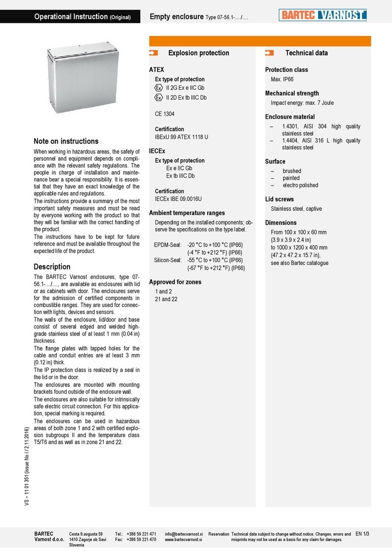
Bartec 07-56.1 Series Quick start guide

Bartec
Bartec 07-56.1 Series Quick start guide

Bartec
Bartec GWR Series User manual