VERIFICATION
Once the H4TU-R is installed, verify that it is operating properly by monitoring the Status
LEDs on the front panel.
LOGGING ON TO THE MAIN MENU
The H4TU-R supports local and remote logon through a maintenance terminal (ASCII
terminal or a PC running terminal emulation software) connected to the craft port on the
H4TU-R front panel.
Logging on creates menus and screens for the H4TU-R that are replicationsof thoseviewed
at the H4TU-C. Once logged on, you can view system settings and inventory, initiate
loopbacks, monitor performance, and configure the circuit.
To log on using a maintenance terminal:
1Press + to refresh the Logon screen, if necessary.
2Press the first letter of the desired menu. Use the to cycle through menu
selections, and press to change a setting or display a menu.
LOOPBACK TESTING
Initiate loopbacks with the H4TU-R loopback pushbuttons, the H4TU-C front-panel
display, the maintenance terminal monitor screen, or with inband codes. The inband codes
shown below can be sent by a test set. For more information on loopbacks, refer to the user
manual for the H4TU-C line unit.
Table 1. LED Status and Functions
LED/Status Function
DSL1
OFF No power is applied to the H4TU-R.
Solid green Loop 1 connected to the H4TU-R has synchronized without error.
Flashing red once every second Loop 1 of the H4TU-R is in acquisition.
Solid red Loop 1 connected to the H4TU-R detects HBER or MARG alarms.
Flash red once every two seconds Download session in progress.
DSL2
OFF No power is applied to the H4TU-R.
Solid green Loop 2 connected to the H4TU-R has synchronized without error.
Flashing red once every second Loop 2 of the H4TU-R is in acquisition.
Solid red Loop 2 connected to the H4TU-R detects HBER or MARG alarms.
Flash red once every two seconds Download session in progress.
ALM
OFF Normal operation: the DS-1 signal is present at both the H4TU-R and
H4TU-C.
Solid yellow LLOS is present at the H4TU-C.
Solid red RLOS is present at the H4TU-R.
DS1
Solid green Normal operation: the DS1 signal at the H4TU-R is error free.
Solid red RLOS, BPV, frame error, or CRC is detected at the H4TU-R.
ESF/SF
OFF Unframed DS1 present at the H4TU-R or no DS1 is detected at the
H4TU-R.
Solid yellow ESF frame formatting is present at the H4TU-R.
Flashing yellow once per second ESF frame formatting and frame error/CRC are present at the H4TU-R.
Solid green SF frame formatting is present at the H4TU-R.
Flashing green once per second SF frame formatting and frame error are present at the H4TU-R.
B8ZS/AMI
OFF No DS-1 signal is present at H4TU-R.
Solid yellow B8ZS line code is provisioned at the H4TU-R.
Flashing yellow once per second B8ZS and excess zeros string are present at the H4TU-R.
Solid green AMI line code is provisioned at the H4TU-R.
Flashing green once per second AMI and BPV are present at the H4TU-R.
RLB/LLB
OFF H4TU-R is not ARMed or in loopback.
Solid yellow H4TU-C is looped back toward the network or customer.
Flashing yellow once per second System is ARMed.
Solid green H4TU-R is looped back toward the network or customer.
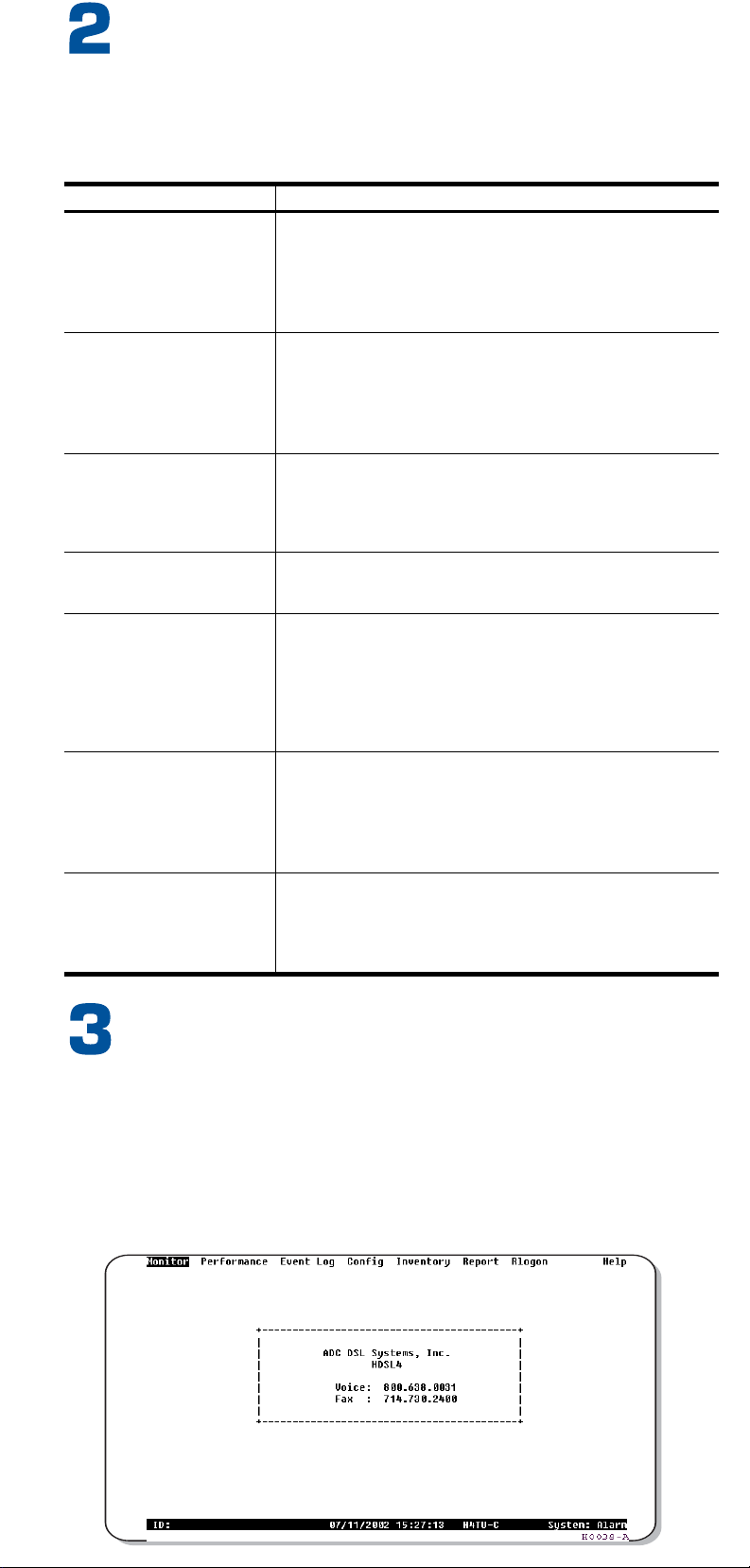
Type the first letter To view:
onitor A graphical representation of circuit activity and devices.
erformance Performance history statistics (current, 25-hour, 48-hour, 31-day, and blockage
indicator) at DS1 and HDSL4 interfaces. Also, displays alarm status and count.
vent log Sectionalized Event History for alarms and errors at all four legs of the DS1 signal at
the H4TU-R.
onfig Configuration options (standard, ADC, signal generation, date and time,
master clear, factory defaults).
nventory Product information, circuit and unit identifications.
logon Maintenance terminal screens at the H4TU-C.
elp Glossary, screen navigation keys, ADC contact information.
Rep rt Downloading status and performance monitoring data to file.
For more information about the HiGain HDSL4 maintenance screens,
refer to the user manual of the H4TU-C line unit. Copies of user
manuals can be downloaded from the ADC website at www.adc.com.
To order a hard copy, please contact your sales representative.
Loopback Commands
Loopback Inband Code Description
NLOC 1111000 DSX-1 signal is looped back to the network at the H4TU-C.
NREM 1110000 DSX-1 signal is looped back to the network at the H4TU-R.
SMJK 11000 DSX-1 signal is looped back to the network at the H4TU-R SmartJack module.
CREM 1111110 DS1 signal from customer is looped back to the customer at the H4TU-C.
CLOC 1111100 DS1 signal from customer is looped back to the customer at the H4TU-R.
Loopdown 11100 Deactivates any of the above loopbacks.
CTRL R
SPACEBAR
ENTER
M
P
E
C
I
R
H
O
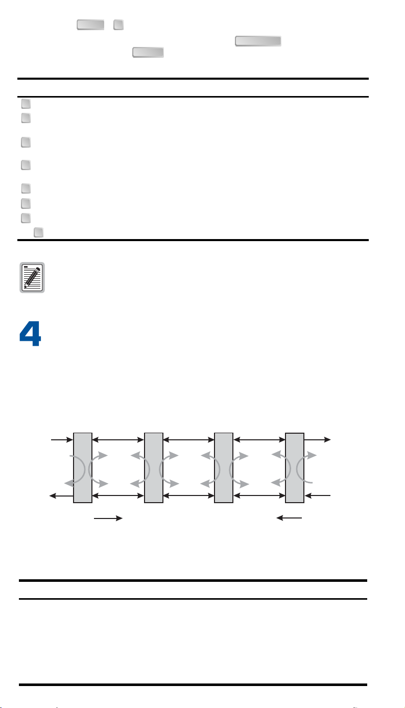
Network Customer
Premises
NLOC NDU1 NDU2 CLOC
CDU1 CDU2CREM NREM
TLOS*
H4TU-C H4D1 H4D2 H4TU-R
SMJK
DS1
DSX-1
*
When enabled,TLOS is an automatic loopback
that occurs with an LOS at the remote DS1 input.
Span 1 Span 2 Span 3
Downstream Upstream
H0068-A
RS-232
DCE
DS1
R
U
ALM
DSL1
ESF/SF
B8ZS/AMI
RLB/LLB
OUT
2
0
4
T
4
H
.
L
DSL Status LEDs
ALM LED
DS1 LED
Framing LED
Line code LED
Loopback LED
CLEI/ECI bar code label
Craft port provisioning
To access all system maintenance, provisioning,
and performance screens, connect a standard
9-pin terminal cable between the serial port on a
PC and the H4TU-R craft port.
Loopback control pushbuttons
Press pushbutton for 5 seconds to activate a dual loopback at the network (RLB) or at
the customer (LLB).
The unit can be looped down by pressing either pushbutton again for 5
seconds, by the standard loopdown inband messages, or by the maintenance terminal.
no active loopback in the system, will activate a bi-directional loopback at the Remote
Unit (loopback at RT towards NET and CPE using LLB) or (loopback at the CO towards
NET and CPE using RLB).
Press both pushbuttons together for more than 2 seconds on one- and two-span syste
(all LEDS on the front panel will reflect the corresponding LED states at the CO) or on a
3-span system (the DSL1 and 2 LEDs will reflect the DSL status of the span between th
1 and 2 repeater). All other LEDs at RT will reflect the LED status at the CO unit. All
LEDs at the RT will resume to the RT LED states when both LLB and RLB buttons are
released. This “Display CO” LED feature is invoked on either H4TU-C-L5A or H4TU-C-L
units.
st nd
Any existing loopback is terminated before these loopbacks are
activated.
Extraction handle
Use to remove the
H4TU-R-402 from
its slot.
DS1 input (OUT) and output (IN) bridging (BRG) jacks
Provides non-intrusive test access.
9600 baud
8 data bits
No parity
1 stop bit
Hardware flow control: OFF
Terminal emulation: VT100
Maintenance Terminal Modem Settings
List number
Indicates the list number of the H4TU-R-402.
BRG
IN
LBK
LLB
RLB
D
S
1
YEL/GRN
H0034-A
DSL2
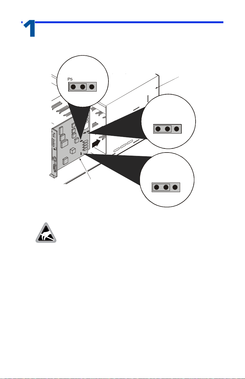
27
25
23
21
19
17
15
13
11
9
7
3
5
1
DS1 Tip
Card-Edge Connector
DS1 Ring
HDSL4 Ring1
HDSL4 Tip 1
Factory Use Only Factory Use Only
Protection Switch Power
DS1 Ring1
Circuit Ground
( - )
( + )
HDSL4 Ring
IN
OUT
HDSL4 Tip
DS1 Tip1
Chassis Ground*
28
26
24
22
20
18
16
14
12
10
8
4
6
2
55
53
51
49
47
45
43
41
39
37
35
32 31
56
54
52
50
48
46
44
42
40
38
36
34
30
33
29
Note: Active pins are highlighted in black.
*Chassis Ground may be tied to earth ground per local practice.
rotection Switch Control
Chassis Ground* -48 Vdc Local Power
HDSL4
Loop1
HDSL4
Loop2
Front Panel