Clearlite Bathrooms Angle Corner User manual
Installaon Instrucons
Angle Corner
Please read these Instrucons carefully
May 2018
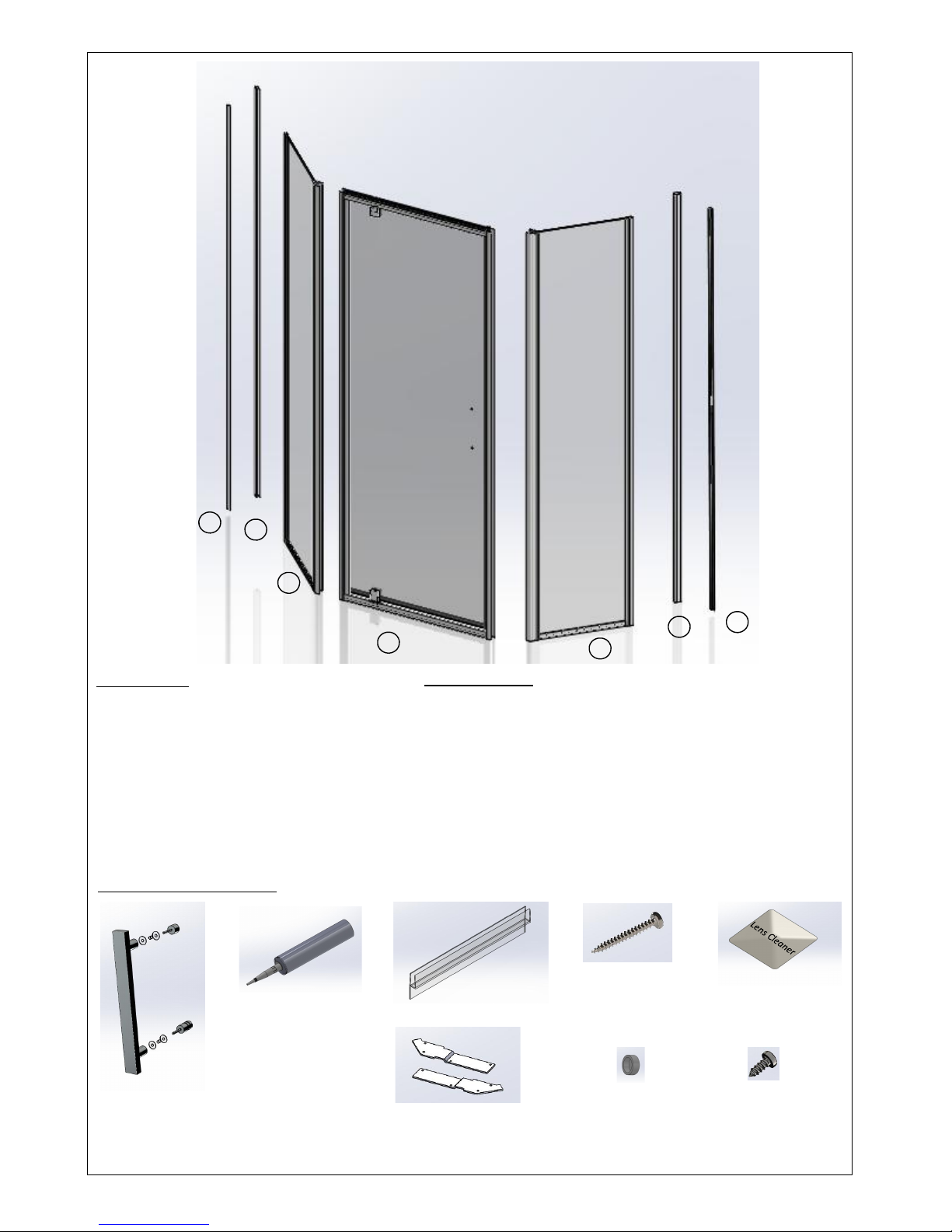
Components
Installaon Components
A –Return Wall Receiver x 2
B - Door Assembly
C - Corner Return x 2
D - Cover Trim x 2 (on Selected Models)
(For shipping purposes the Wall Receivers are packed in the sides of the Return
Handle
(where applicable)
Drip Seal –1m
No.6 x 10mm
screw Qty 24
No.6 x 38mm
screw Qty 6
Screw Cap
Qty 12
Drill
Spirit level
Tape Measure
Screw Driver (No.1 Sq drive)
Tools Required
Caulking Gun
Masking tape
Pencil
Cleaning Cloth
Tube of NG Silicone
(Colour matched to
shower)
B
D
C
A
A
D
C
Drip Seal –1m
Brackets
Le and Right
Cleaning Towelee
(White showers only)

Installaon
Note:
Your shower Door can be installed to open from the le or right hand side by rotang the door
180 degrees, and the Return Panels can be fied on either side. You must decide which way the
door is to open before starng the installaon.
1) Posion the Wall Receivers hard against
the inside edge of the tray upstand. “V”
groove line facing towards the inside the
shower
NOTE: If the shower walls are to be led
the Wall Receivers must be installed to
the Water proof membrane before ling.
This ensures the doors will fit within
the lip of the tray
2) Plumb up the Wall Receiver using a
spirit level. Mark the posion with a
pencil line.
Repeat on adjacent side for the Re-
turn Wall Receiver

3) Pre drill three equally spaced clearance holes
(i.e. top, boom and centre) in the Door &
Return Wall Receivers using a 4.5mm drill
bit. Reposion the Wall Receivers to the
pencil line on the wall. Drill into the wall
through the clearance holes using the
3.0mm drill bit. N.B. The holes preferably
locate into a stud or nog. As an alternave,
a toggle system can also be used.
4) Secure the Wall Receivers to the
walls using the No.6 x 38mm
stainless steel screws
NB As a precauon apply silicone
into the drilled holes
5) A Return Sill is supplied with each of the
Return panels and is only temporarily clipped
to one end of the panel. As the Return panel
can be installed le or right hand it is necessary
to remove the sill, apply sealant and aach to
the correct end of the Return panel
6) Apply a small connuous bead of NG
Silicone sealant into the boom of the
Return sill channel. Do not fill the
channel with silicone as this will be
excessive and the majority will ooze
out making cleanup difficult
Wall Receivers
Return Panels

7) Fit the Return Sill to the lower edge of the
Return Panel. Carefully wipe away any
excess silicone that may ooze out
11) Fit the handle to the door (where required). This
will assist in the opening & closing during the in-
stallaon process
Ensure to fit the plasc washers and bush to prevent
metal on glass contact
8) Place 25-50mm Wood packers on the
tray (not supplied)
9) Posion the Return Panel into the Return Wall
Receiver.
11) Repeat steps 5 – 10 for the adjacent Return Panel
10) Slide the return Panel down onto the
packers
12) Carefully swing the Return Panels outwards
Door Installaon
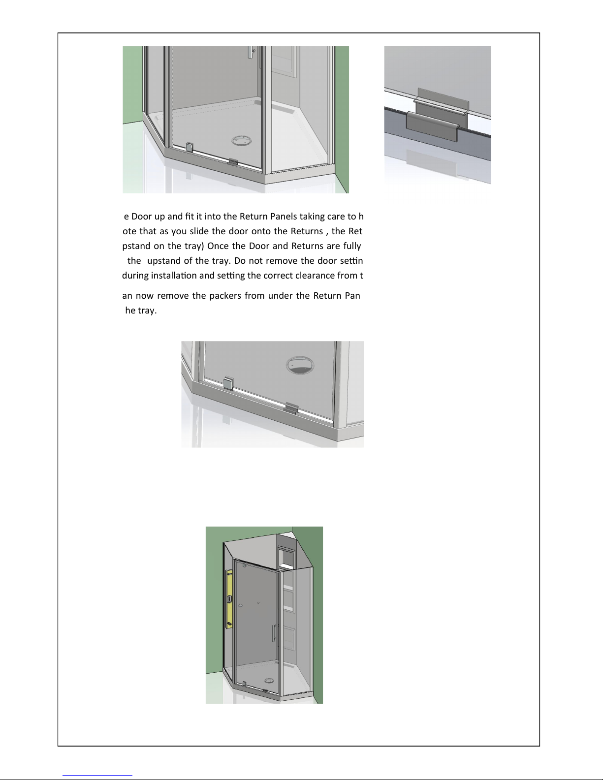
14) For Sureseal trays the Door and Return Panels should be close to the inside edge of the tray’s upstand
as possible
For other applicaons, check that the doors are parallel with the front edge of the tray.
13) Li the Door up and fit it into the Return Panels taking care to hold it above the front lip of the tray (You
will note that as you slide the door onto the Returns , the Return Panels will self align to the inside of
the upstand on the tray) Once the Door and Returns are fully engaged let the Door slide gently down
inside the upstand of the tray. Do not remove the door seng block, this will assist in supporng the
door during installaon and seng the correct clearance from the sill
You can now remove the packers from under the Return Panels and allow them to slide gently down
onto the tray.
15) Adjust the Door set ensuring the corner posts line up with the corners of the tray and that they are
sing plumb and level.
21) Slide the outside Clamp Block Covers off the
Pivot Clamp. Using a flat blade screwdriver
sufficiently loosen the two screws, adjust the
door by sliding le or right in the pivot
Once the door adjustment is complete ensure
the screws are reghtened and reinstall the
Clamp Block Covers. Open the door and re-
move the door seng block
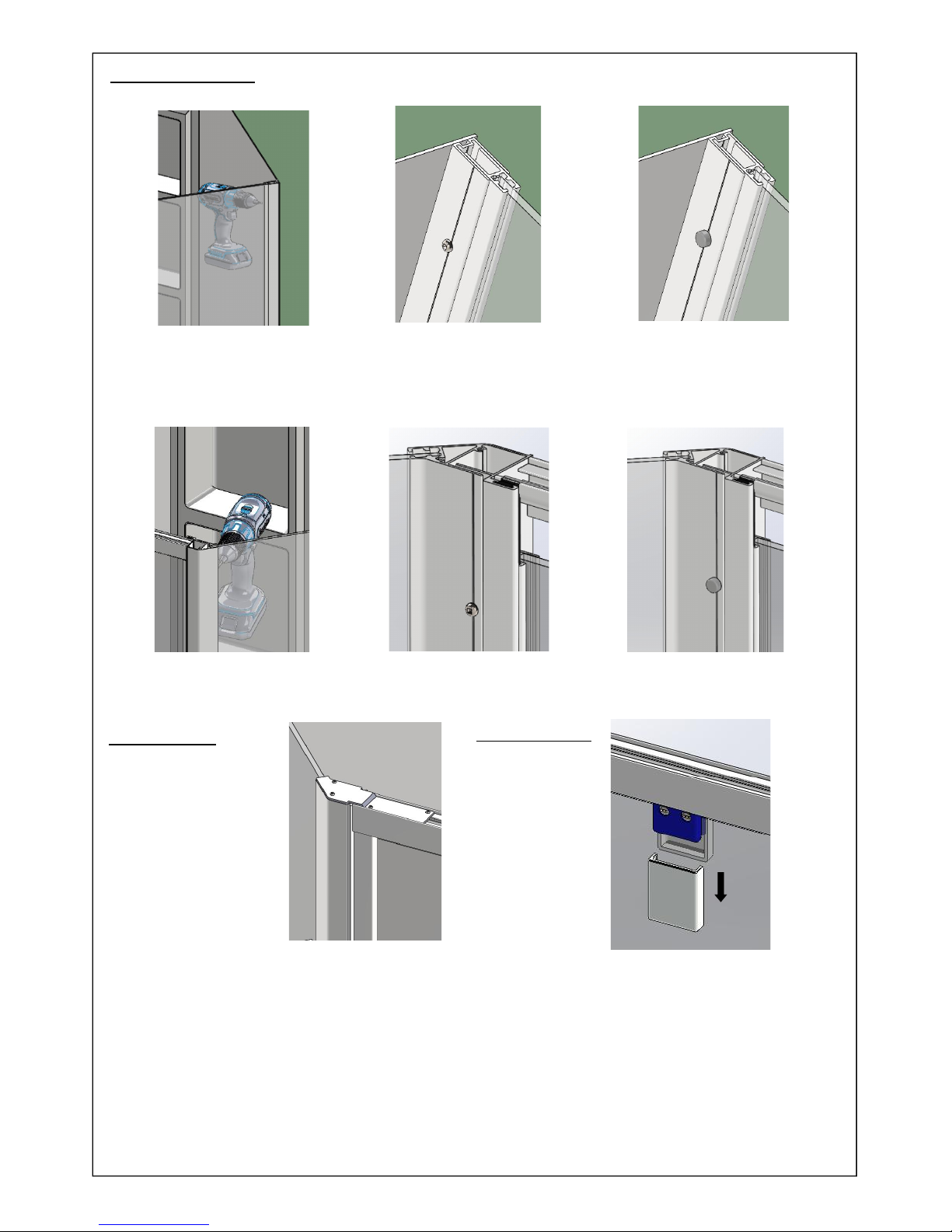
18) Using a 3.0mm drill bit, drill through the Wall Receiver secons and into the Return frames. (Use the “V”
groove line as a guide). Secure the Door set together using the No.6x10 Screws. Cover the screw heads
with the Cover caps
20) Posion le and right hand corner brackets over
the Corner posts
Using the No.6 x 10 screws secure the brackets into
the screw ports of the Corner Post. For the remain-
ing holes drill through the bracket holes into the
Door profile (3.0 mm drill bit) and fix in place using
No.6 x 10mm screws
No Cover caps are required for these screws
19) Repeat for the Corner posts into the Door frame
Secure the Door Set (All Screw fixings are made from the Inside)
Adjust the Door
Brace Brackets

22) The Drip seal is supplied in a 1m length, this will need to be
cut to the desired lengths for each side of the pivot . The
opening side Drip seal will also need to be notched to fit
under the door magnet profile. Make the Notch 13mm in
length and finishing down to the horizontal ledge of the
drip seal
Notch under Door Magnet profile
24) For White Showers only - take the Cleaning
Towelee and wipe the surfaces of the
Powder coated profiles where Silicone will be
applied Allow to dry (1-2 minutes)
Sealing the Shower
26) Cover Trim– (selected models only)
The Cover Trim is provided to cover the exposed
vercal edge of the wall liner and is the final step
of the installaon. For some installaons the Cover
trims may require cung to length
To fit the Cover trim apply small vercal beads of silicone down
the Wall Receiver and the exposed wall lining outside of the Wall
Receiver. Embed the Cover trim into the silicone. If the
25) The Door and Returns can now be sealed in
place using silicone sealant. Ensure all surfac-
es are first cleaned with dry clean cloth. Seal
between the tray upstand and the door set
along the boom outside edges. Seal ver-
cally between the Wall Receivers and Wall
Liner
Note MASKING the area to be Sealed will result
in a superior finish
27) Your Shower is now complete. Allow a
Sealants to cure for a minimum of 24 hrs
IMPORTANT: DO NOT apply sealant to the inside of the shower
Drip Seals
23) Fit the Drip Seals to the glass door
Other Clearlite Bathrooms Other manuals


