ClearPlus Catalytic CP-CC-5800SXT Series Troubleshooting guide

OWNER’S MANUAL & INSTALLATION GUIDE
APPLICABLE MODELS: CP-CC-5800SXT Series
PLEASE READ THIS MANUAL CARE ULLY BE ORE
ATTEMPTING INSTALLATION. AILURE TO OLLOW THESE
INSTRUCTIONS MAY A ECT THE PER ORMANCE O YOUR
SYSTEM, VOID YOUR WARRANTY, AND RESULT IN
PROPERTY DAMAGE.
2
Congratulations on the purchase of your ClearPlus Catalytic™ Series filtration system.
You have purchased one of the finest catalytic carbon water treatment systems on the
market today.
All ClearPlus Catalytic™ Series water treatment systems utilize Calgon Centaur media, the
world's leading catalytic carbon for water treatment.
The brain of your ClearPlus Catalytic™ system is the Fleck 5800SXT control valve. It is
manufactured by one of the world’s premier water treatment companies. The Fleck 5800
control valve is well respected for its reliability, serviceability, simple operation, and value.
The integrated Fleck SXT digital valve controller offers unsurpassed simplicity of operation,
yet complete control over all important valve operations. The Pentair Fleck 5800SXT
Downflow/Upflow Service Manual is also included with your system. It includes additional
information regarding the operation of your valve, replacement parts lists, and more.
Your ClearPlus Catalytic™ water treatment system is designed to offer low maintenance
operation. The control valve will perform regular backwash functions automatically. For
your convenience, your system has been pre-programmed for you at our factory. Should
you need to change any of the settings, simply follow the instructions provided in this
manual.
This manual is designed to provide owners, installers, and service technicians with detailed
information about the installation, start-up, and operation of your new filter system.
IMPORTANT SA ETY SYMBOLS
Hazards or unsafe practices that may result in personal injury
and/or severe property damage.
Hazards or unsafe practices that may cause operational
problems with your water treatment system.

3
Table of Contents:
GENERAL WARNINGS ……………………………………………………………………………………………...….. …….. 4
OPERATING CONDITIONS …………………………………………………………………………………………….…... 5
INSTALLATION ………………………………………………………………………………………………………….…..…..….. 6
Step 1 – Pre-Installation Inspection ……………………………………………………………..……… 7
Step 2 – Selecting an Installation Location ………………………………………………..…..... 7
Step 3 – Prepare Treatment Tank ………………………………………………………………..……… 8
Step 4 – Turn off the Water & Electric Water Heaters ………………………………….… 11
Step 5 – Prepare and Install Inlet and Outlet Plumbing Connection …….…… 12
Step 6 – Drain Line Installation …………………………………………………………………………..… 14
Step 7 – Control Valve Set-up ………………………………………………….……………………….….. 16
Step 8 – Initial Start-up and Leak Testing …………………………………………………......…. 18
BACKWASH ………………………………………………………………………………………………………………….…..……. 19
CHANGING TIME OF DAY ………………………………………………………………..…………………………..…… 21
USER PROGRAMMING MODE ……………………………………………………………………………………..…. 21
MASTER PROGRAMMING MODE ………………………………………………………………………….……..… 22
RESETS ……………………………………………………….…………………………………………………………………….…… 23
OPERATION DURING A POWER FAILURE ………………………………………………………….…..…… 24
MAINTENANCE & TROUBLESHOOTING ……………………………………………………….…..….……. 24
WARRANTY INFORMATION ………………………………………………………………………………………..…… 27

4
GENERAL WARNINGS
Do not allow children or pets to play on or around the water filter.
Do not install or store this filter system where it will be exposed to freezing temperatures.
Do not tamper with controls.
Do not repair, replace, or attempt to service any part of the system unless specifically
instructed to in this manual and you have the understanding, tools, and skills necessary to
carry out the procedure.
Packing materials can be dangerous to children. Keep all packing material (plastic bags,
polystyrene, boxes, etc.) well out of children’s reach.
Individual components of this water treatment system, and the installed system, are heavy.
Precautions should be taken to prevent personal injury or strain. Do not move heavy
components without assistance if you are not physically capable of safely carrying out the
procedure.
If the water treatment system is to be left unattended for an extended period of time
(vacation, etc.), we strongly recommend that you turn off the water supply to the system, or
the whole house, while you are away.
If your water pipes are metal (galvanized or copper), they may be used to ground electrical
systems, appliances, or your phone line. If this is the case, be sure to install regulation
ground clamps to the metal pipe on each side of the control valve and connect a jumper
wire between the 2 clamps (#4 gauge solid copper wire recommended). Consult a certified
electrician or plumber if you are unsure.
5
OPERATING CONDITIONS
The following chart provides guidance on the conditions required for successful operation of
your ClearPlus Catalytic™ system.
USE O THIS EQUIPMENT OUTSIDE O THESE OPERATING CONDITIONS MAY
ADVERSELY A ECT THE PER ORMANCE O YOUR SYSTEM, RESULT IN SYSTEM
DAMAGE INCLUDING WATER LEAKS AND CORRESPONDING PROPERTY DAMAGE, AND
MAY VOID YOUR WARRANTY.
Minimum Water Pressure 20 PSI
Maximum Water Pressure 90 PSI*
Recommended Water Pressure 40-70 PSI
Water Temperature 36F to 100F (2 to 38C)
Minimum Air Temperature 32°F (0°C)**
pH Range 5.0*** to 9.0
* While the ClearPlus Catalytic™ system is built to withstand pressures exceeding 90 PSI, if
your water pressure is greater than 70 PSI, we recommend that you have a certified plumber
install a pressure reducing valve ahead of the ClearPlus Catalytic™ system.
** The system cannot be subjected to freezing conditions or severe damage to the system
and your property could occur.
*** pH correction is strongly recommended where pH levels are less than 6.5 to prevent
damage to your control valve and plumbing system, and to prevent leaching of metals from
copper and brass plumbing components and solder in your home. Contact your dealer for
recommendations.
For best contaminant removal, the optimal service flow rate should not be exceeded.
Satisfactory to good filtration can generally be achieved up to the recommended maximum
service flow rate as long as this level of flow rate is not sustained continuously. See chart
below.

6
ClearPlus Catalytic™ Series low Rates & Backwash Requirements:
Model
Optimal
Service low
Rate* (GPM)
Maximum
Service low
Rate* (GPM)
Backwash low Rate
at 40 Water Temp
(GPM)
Backwash low Rate
at 70 Water Temp
(GPM)
CP-CC-5800SXT-8-44
2.5 3.5 3.5 4
CP-CC-5800SXT-9-48
3.5 4.5 4.5 5
CP-CC-5800SXT-10-54
4.0 5.5 6 6
CP-CC-5800SXT-12-52
5.5 8.0 8 9
CP-CC-5800SXT-13-54
6.5 9.0 9 10
CP-CC-5800SXT-14-65
7.5 10.0 10 12
CON IRM THAT YOUR WATER CONDITIONS, SERVICE LOW RATE NEEDS, AND
AVAILABLE BACKWASH LOW RATES MEET THE ABOVE SPECI ICATIONS OR THE
MODEL YOU ARE INSTALLING BE ORE COMMENCING THE INSTALLATION PROCESS.
I IN DOUBT, CALL YOUR DEALER OR ADVICE. INSTALLED UNITS CANNOT BE
RETURNED.
INSTALLATION
WE RECOMMEND THAT YOU READ THIS ENTIRE MANUAL BE ORE STARTING THE
ACTUAL INSTALLATION. WHILE WE STRONGLY RECOMMEND THAT A LICENSED
PLUMBER PER ORM ALL INSTALLATION WORK, A MECHANICALLY-INCLINED
HOMEOWNER WITH SUITABLE PLUMBING KNOWLEDGE CAN INSTALL THIS SYSTEM.
IN ALL CASES, IT IS CRITICAL THAT THE INSTALLATION BE DONE IN ACCORDANCE
WITH THESE INSTRUCTIONS AND ALL APPLICABLE PLUMBING AND ELECTRICAL
CODES. BE SURE TO OBTAIN ALL REQUIRED PERMITS. I THESE INSTRUCTIONS AND
THE APPLICABLE CODES ARE IN CON LICT, THE RELEVANT PLUMBING/ELECTRICAL
CODE SHALL BE OLLOWED. EQUIPMENT AILURE, PERSONAL INJURY, OR PROPERTY
DAMAGE CAN RESULT I THIS EQUIPMENT IS NOT INSTALLED PROPERLY.

7
Step 1. – Pre-Installation Inspection
Inspect all of the components that you received with
your unit. You should have received the following:
1. Fleck 5800 SXT Control Valve
2. Media Tank
3. Upper Screen
4. Bypass Assembly w/ 1” NPT Connector Yoke
5. Riser tube and lower distributor
6. Bag or box of gravel
7. Bag(s) or box(es) of Catalytic Carbon media
8. Funnel
9. Drain Line Flow Control - DLFC (attached to #1)
Step 2. – Selecting an Installation Location
While exterior installation in warm climate areas is possible, we strongly recommend interior
installation only. The system cannot be allowed to freeze or severe system damage could
occur. The system should not be exposed to rain and it should not be installed in direct
sunlight, as long-term exposure to UV light could damage components of the system.
Furthermore, direct sunlight could raise the internal water temperature in the treatment tank
and reduce backwash effectiveness.
In most cases, the system should be located AFTER your water pump and pressure tank(s)
and BEFORE all other water treatment equipment and your hot water heater.
I YOU HAVE OTHER WATER TREATMENT EQUIPMENT, YOU SHOULD DISCUSS THE
ORDER O YOUR TREATMENT EQUIPMENT WITH YOUR DEALER PRIOR TO
INSTALLATION.

8
Select a location for installation of your water filter that is within close proximity to the main
incoming water line of the home. The location should have a firm, level surface with enough
space for the unit itself and sufficient space surrounding the unit to facilitate maintenance.
WHILE WATER LEAKS ARE VERY RARE AND UNEXPECTED, YOUR WATER ILTER
SYSTEM SHOULD BE LOCATED NEXT TO A LOOR DRAIN OR PROTECTED BY A WATER
LEAK DETECTION SYSTEM WITH AUTOMATIC SHUT-O VALVE TO PREVENT WATER
DAMAGE TO YOUR PROPERTY IN THE UNLIKELY EVENT O A WATER LEAK.
RECOMMENDED WATER LEAK DETECTION SYSTEMS ARE AVAILABLE AT WWW.A-LEAK-
DETECTOR.COM.
You will also require a suitable drain to discharge waste water from the backwash cycle. A
drain standpipe for a washing machine, floor drain, or sump pump are excellent drain
options. We recommend that the drain line be connected to a minimum 1½" drain
standpipe or floor drain located ideally below the top of the head of your water filter. If
possible, the drain should be no farther than 20 feet from the system.
NOTE: NEVER CONNECT THE DRAIN LINE DIRECTLY INTO A DRAIN PIPE. ALLOW AN AIR
GAP BETWEEN THE DRAIN TUBING AND WASTE LINE TO PREVENT THE POSSIBILITY
O BACK-SIPHONING. WE DO NOT RECOMMEND USE O A CHECK VALVE AS IT MAY
BECOME CLOGGED WITH CONTAMINANTS EJECTED ROM THE SYSTEM DURING
BACKWASH.
You will also need access to a standard, non-switched, grounded 120 volt (60 Hz) electrical
outlet. An extension cord may be used to reach a suitable electrical outlet. If this option is
used, ensure that the extension cord is UL/CSA certified and of an appropriate wire gauge
for the application.
Step 3. – Prepare Treatment Tank
Two types of media are supplied with your ClearPlus Catalytic™ system: gravel which forms
the base layer (underbedding) in your treatment tank, and Centaur Catalytic Carbon.

9
Place the tank in the location where it will sit when the installation is complete. Note that the
black base of your tank is not permanently attached to the rest of the tank. If your tank
appears to be crooked, the base has likely been knocked out of alignment during shipping.
This can be correct by picking the tank up and tapping it on a hard surface while holding it
perpendicular to the floor. A few light taps will generally straighten it out.
Temporarily remove the distributor and riser tube assembly from the treatment tank. Hand
tighten the Fleck 5800SXT control valve on the tank and mark where the front of the tank will
be. Turn the tank so that the front of the tank is where you want it when it is full – once it is
full of media and water, it becomes very heavy and difficult to move!
Remove the control valve and re-insert the distributor and riser tube assembly into the tank.
The distributor, which looks like a cone-shaped plastic screen, is pre-connected to the end of
the long plastic riser tube which extends from the bottom of the tank to the top of the tank
where the control valve is attached. At the bottom of the tank, there is a recess in the center
of the tank to accept the distributor to keep it properly aligned. The riser tube has been pre-
cut to the correct height for you. When the distributor is correctly positioned, the top of the
riser tube will be approximately 1/8 to 1/4 of an inch below the top of the tank. If the tube is
flush or protruding above the top of the tank, the distributor tube is not nested correctly in the
recess at the bottom of the tank.
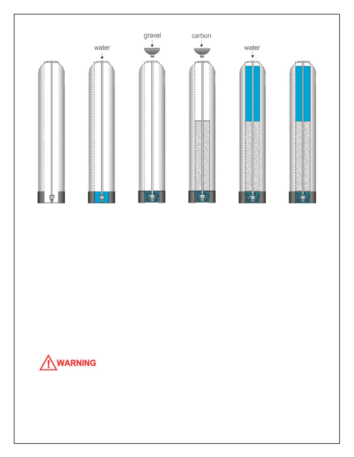
Add enough water to the tank to cover the lower distributor with a minimum of 6 inches of
water. This will prevent damage to the lower distributor as gravel is loaded. Place the funnel
into the tank so that the riser tube is in the middle. Place tape over the open end of the riser
tube. This will prevent gravel or media from accidentally going down the tube during the
following steps.
For the following steps, we recommend that you wear a dust mask. Take the bag/box of
gravel and, using a small scoop, add the gravel to the tank through the funnel to completely
cover the lower distributor. Use all of the gravel. Be sure to provide some downward
pressure on the riser tube while adding the gravel to ensure that the distributor does not shift
out of its recess or rise up. Ensure that you create an even layer of gravel across the bottom
of the tank. A rigid piece of thin wall tubing (conduit, copper pipe, etc.), approximately 1”
longer than the tank height works well as a leveling tool if you need it. Ensure that the riser
tube remains centered in the opening at the top of the tank.
10
Once this is complete, add the Catalytic Carbon media in the same manner. Use all of the
media provided. Depending on the capacity of the system, there will only be enough media
to fill the tank to about 1/2 to 3/4 full. This is normal. The media tank should never be filled
to the top of the tank as the remaining space, known as the “freeboard,” is necessary for the
media to have room to expand during the backwash cycle.
Once you have finished adding the media to the tank, remove the tape from the distributor
tube. Be careful not to pull upwards on the riser tube while doing this as it is important that
the distributor remain in its recess at the bottom of the tank.
Fill the media tank with water up to within a couple of inches of the top of the tank. This will
allow the media to pre-soak, thereby preventing media loss during the initial backwash.
DO NOT INITIATE A REGENERTION O THIS SYSTEM OR A MINIMUM O 2 HOURS
A TER ADDING THE WATER TO ALLOW ADEQUATE PRE-SOAKING. BACKWASHING
BE ORE THE MEDIA IS SATURATED MAY CAUSE A LOSS O MEDIA AND POTENTIAL
DAMAGE TO THE CONTROL VALVE.

11
Attach the upper screen to the underside of the control valve.
Be sure to twist clockwise and lock it into place.
Apply a small amount of lubricant to the top inch of the outside
of the riser tube and to the tank o-ring seal.
Note: Only use food-grade silicone lubricant. A small bag of
lubricant is provided in the small parts bag. Do NOT use
petroleum jelly.
The control valve can now be secured to the top of the tank.
Before attaching the valve, check to make sure that there is no
debris such as gravel or media in the tank threads. Screw the
control valve onto the tank – make sure that the riser tube inserts
into the center hole in the upper screen and the control valve as
you screw down the valve. The control valve should be hand-tightened
(clockwise). Do NOT use the control valve's timer assembly for leverage and do not use
tools. A firm grasp with both hands at the base of the valve will work. Do NOT use pipe
cement (“pipe dope”) or Teflon® tape on the threads.
Step 4. – Turn off the Water & Electric Water Heaters
AILURE TO OLLOW THIS PROCEDURE COULD RESULT IN SERIOUS, PERMANENT
DAMAGE TO THE HEATING ELEMENTS IN YOUR WATER HEATER.
If you have a conventional electric water heater or an on-demand (tankless) electric water
heater, we highly recommend that you turn off the power to the heater while installing any
water treatment equipment. Turn off power to your water heater now.
Turn off the household main water shutoff valve. Open several plumbing fixtures inside the
home as well as the outside faucets to drain as much water out of the plumbing system as
possible.
Following completion of the entire installation, restore the water flow by turning on the
household main water valve and allow all air to be purged from the plumbing system before
turning the power back on to your water heater.

12
Step 5. – Prepare and Install Inlet and Outlet Plumbing Connections
TE LON® TAPE IS THE ONLY SEALANT TO BE USED ON THE 1” NPT CONNECTOR YOKE
AND DRAIN ITTINGS.
I YOU WISH TO USE COPPER PIPING OR YOUR INSTALLATION AND WILL BE
SOLDERING THE JOINTS, DO NOT APPLY HEAT NEAR YOUR CONTROL VALVE, BYPASS
ASSEMBLY, 1” NPT CONNECTOR YOKE, OR THE DRAIN ITTINGS; OTHERWISE SERIOUS
DAMAGE TO THESE PARTS COULD OCCUR. ALWAYS SOLDER JOINTS WITH THESE
COMPONENTS DETACHED. I YOU ARE USING COPPER ADAPTERS TO CONNECT TO
THE 1” NPT CONNECTOR YOKE, IT IS RECOMMENDED THAT YOU SOLDER A 6" PIECE
O COPPER PIPE INTO EACH O THE CONNECTION ADAPTERS AWAY ROM THE
VALVE, THEN LET THEM COOL O BE ORE THREADING THEM ONTO THE 1” NPT
CONNECTOR YOKE.
Key Control Valve Components:
1. Control Valve Body
2. Bypass Assembly
3. 1” NPT (Male) Connector Yoke
4. Stainless Steel Clip w/ Screw
5. Drain Line Flow Control (DLFC)
6. Valve Cover
7. DLFC Retention Clip
The system’s control valve is
connected to your incoming and
outgoing water lines by way of a
bypass assembly with 1”NPT
threaded fittings. This assembly is
composed of the bypass valve and
the 1”NPT connector yoke. The 2 piece bypass assembly is secured to the control valve
using 2 stainless steel clips. Similarly, the 2 pieces of the bypass assembly, the bypass and
the 1” NPT connector yoke, are connected to each other in the same manner (they are
13
normally shipped to you pre-connected, but you can separate them to make plumbing
easier if you want). You will need to purchase the appropriate NPT threaded fittings to
connect the bypass assembly to the material and size of your main inlet and outlet water
lines.
Locate the inlet and outlet ports on the back of the control valve. Note that the inlet and
outlet are marked with arrows indicating the correct direction of water flow. When you are
looking at the back of the control valve, the inlet is on the left and the outlet is on the right.
Check the corresponding markings on the bypass to ensure the correct direction of water
flow and insert the bypass (do not secure the clips yet). The in and out arrows on the bypass
should be pointing the same direction as the in and out arrows on the outside of the control
valve.
BE VERY CARE UL TO MAKE SURE YOU PLUMB THE SYSTEM IN THE RIGHT DIRECTION.
Plumb your main incoming and outgoing water lines using suitable pipe, fittings, elbows, etc.
as necessary to create a tidy, secure installation up to the back of the bypass valve
(including the correct connection adapters to mate with the threaded fittings on bypass
assembly’s connection yoke. Be sure to follow all local plumbing codes.
WE HIGHLY RECOMMEND THAT YOU REMOVE THE BYPASS ASSEMBLY ROM THE
CONTROL VALVE BE ORE MAKING THESE INAL CONNECTIONS AS YOU MAY
INADVERTENTLY APPLY TOO MUCH PRESSURE ON THE VALVE WHILE SECURING THE
ADAPTERS, CAUSING DAMAGE TO THE VALVE BODY.
Once all plumbing to the bypass has been completed, you can connect the bypass
assembly to the control valve. Push the bypass onto the back of the control valve and
secure it using the two stainless steel clips with screws located on the back of the control
valve. Do not overtighten - it is normal for some “play” to exist when the bypass assembly is
properly seated. This allows for minor misalignment of the piping connections and relieves
stress on the valve.
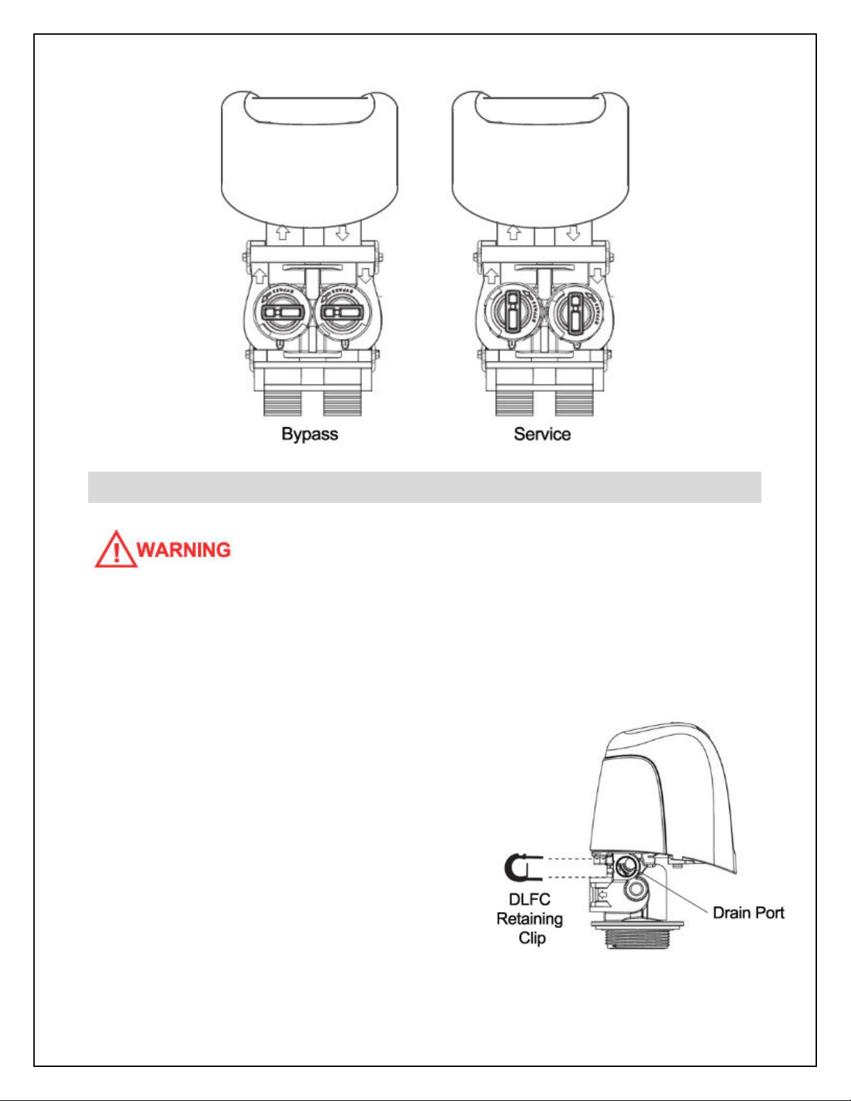
Place the bypass in the “bypass” position as pictured:
14
Step 6. – Drain Line Installation
NOTE: NEVER CONNECT THE DRAIN LINE DIRECTLY INTO A DRAIN. ALLOW AN AIR-GAP
O A MINIMUM O 1 INCH (CHECK LOCAL CODES) BETWEEN THE DRAIN LINE AND
WASTE LINE TO PREVENT THE POSSIBILITY O BACK-SIPHONING. ALWAYS OLLOW
LOCAL CODES. THE DRAIN LINE SHOULD NOT BE EXPOSED TO REEZING
TEMPERATURES.
During the backwash cycle, your system will
send captured contaminants out the drain port. This
port needs to be connected to a suitable household
drain, ideally within 20 feet of your media tank. A
nearby floor drain, sump pump, or a standpipe for a
washing machine is an excellent option. We
recommend that the drain line be connected to a
minimum 1 1/2 inch drain standpipe or floor drain
located ideally below the top of the head of your
water filter.
15
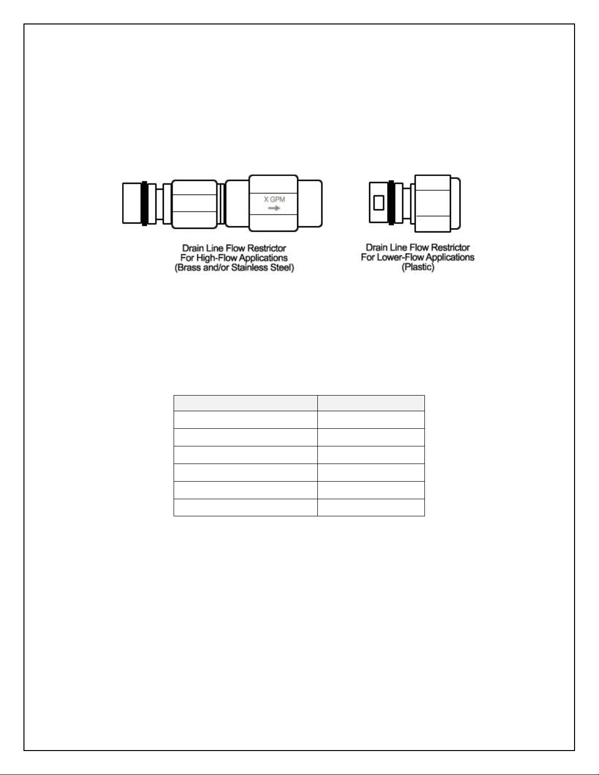
Locate the drain port on the back of your control valve. The drain line flow control assembly
(DLFC) is pre-attached to the control valve. For backwash flow rates of 7 GPM or less, the
DLFC will be a black plastic housing with 1/2 inch female NPT threads. This housing
contains a flow control washer that limits the backwash flow rate. For backwash flow rates
exceeding 7 GPM, the DLFC will be a brass adapter with a pre-attached external flow
restrictor with 3/4 inch female NPT threads.
You will need to purchase suitable pipe or tubing for the drain line, either 1/2 or 3/4 inch
diameter, to match the connection points on the drain line flow control assembly (DLFC). To
determine your MINIMUM drain line diameter, look up your model and incoming water
temperature using the chart below. If in doubt, use a 3/4 inch drain line.
MINIMUM Drain Line Diameter:
Model Min. Drain Line
CP-CC-5800SXT-8-44 1/2"
CP-CC-5800SXT-9-48 1/2"
CP-CC-5800SXT-10-54 1/2"
CP-CC-5800SXT-12-52 3/4"
CP-CC-5800SXT-13-54 3/4"
CP-CC-5800SXT-14-65 3/4"
Polyethylene tubing, PEX, PVC, CPVC, or copper pipe are all acceptable material choices for
the drain line. If you are using flexible tubing, be sure that there are no “kinks” or “crimps” in
the tubing after installation that may cause a flow restriction. If used, overhead drain lines
are not to exceed a height of 5 feet above the control valve and should be not more than 50
feet in length. Should an overhead drain line be utilized, it is recommended that the drain
line be increased in size (diameter), and that it not be fastened flush to the bottom of a floor
joist to minimize noise transfer to the upstairs of the building during regeneration.
Using an appropriate fitting, connect the drain line flow control to your drain line tubing/pipe.
The DLFC can be removed from the control valve to facilitate easier plumbing if desired. To
16
remove the drain line flow control, pull on the retaining clip to remove it and then grasp the
drain line flow control and pull outward. You may wish to dry-fit the fitting first to make sure
you line up the drain line properly with the drain port on the control valve if you are using
rigid pipe.
Re-insert the DLFC into the control valve and securely lock into place with the retaining clip
when done.
Ensure that the drain line is thoroughly secured along its route to the drain. The drain line
will be under pressure when the backwash cycle is working. If not adequately secured, the
drain line could vibrate during backwash causing excessive noise. If this is experienced, use
additional fixtures to better secure the drain line.
Step 7 – Control Valve Set-up
During cold weather, the installer should warm the control valve to room temperature before
operating. Note: All electrical connections must be done according to local codes.
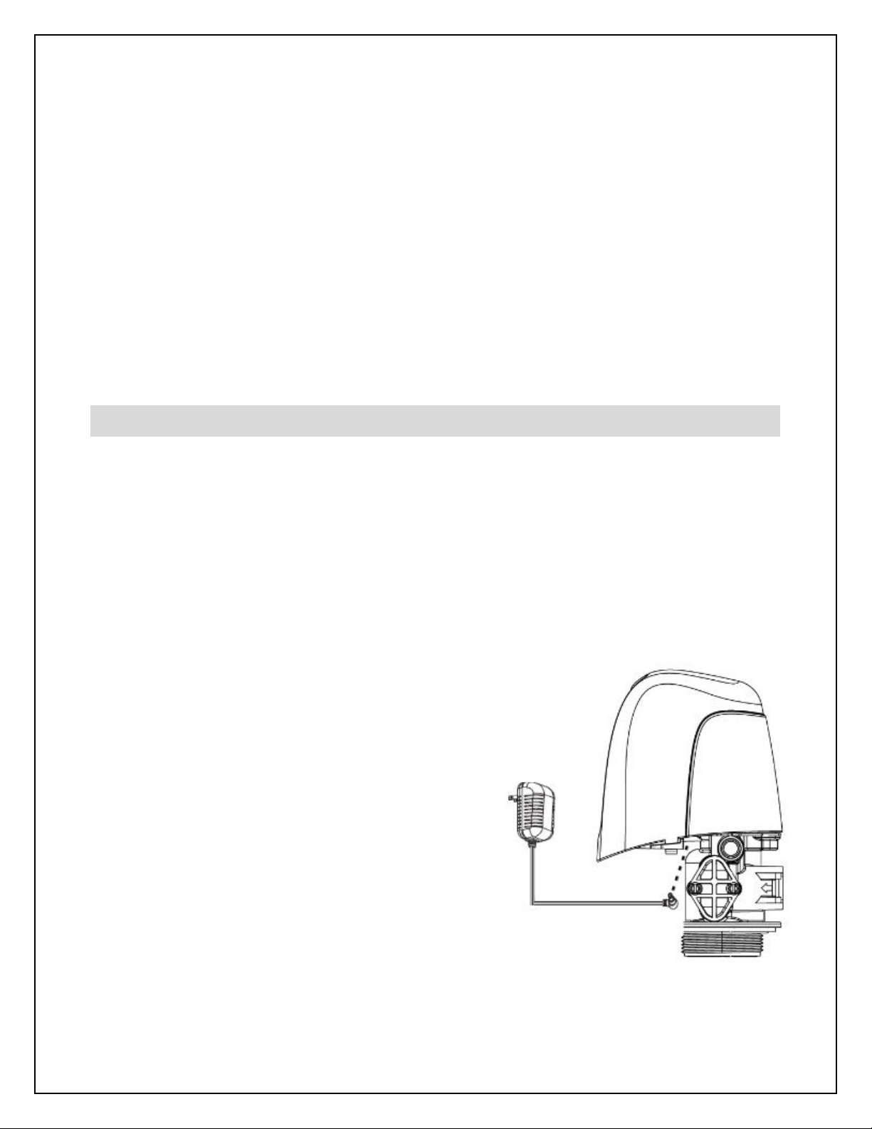
Plug the control valve into a standard, grounded 120 volt (60 Hz) electrical outlet. Be certain
that the outlet is uninterrupted and not controlled by a switch. An extension cord may be
used to reach a suitable electrical outlet. Ensure that the extension cord is UL/CSA certified
and of an appropriate wire gauge for the application. Plug the other end of the power cord
into the electrical port on the control valve.
Note: The electrical port on the control valve is
located on the right side of the valve (when you
are facing the control panel), just behind the tab
used to remove the valve cover. It is a bit tricky
to find.
Once plugged in, the digital display on the control
valve will illuminate. The control valve may need
to reset to the home position when it is powered
up. If it does, the motor will run for a few seconds.
The digital display should be alternating between

17
the current time setting (which is probably incorrect), and the number “5” which indicates the
number of days remaining until the next backwash cycle. You will also see the “service” icon
which appears as a small faucet in the bottom left corner of the display window.
We will first set the time of day to the correct time. Press either the UP or DOWN button and
hold for a few seconds. The parameter display will read “TD” (Time of Day) and the
“programming” mode icon will appear (4 dots and a pencil). Use the UP and/or DOWN
buttons to change the time displayed to the correct time of day. Once the display shows the
correct time, press the EXTRA CYCLE button to save your changes.
Your ClearPlus Catalytic™ has been pre-programmed to backwash every 5 days and to
perform the backwash process at 12:30am in the morning when it is very unlikely that water
will be required in the building. If water is required during the backwash process, untreated
water will be permitted to flow to meet your service needs. You may edit the frequency and
duration of the backwash based on your water conditions. You may also alter the time of
day that the backwash process occurs if 12:30am is not ideal for you. If you have a water
softener or other automatic backwashing water treatment systems, make sure that they are
not set to backwash / regenerate at the same time. We recommend that they

18
backwash/regenerate at least 2 hours apart. Follow the instructions under “User
Programming Mode” to change the frequency or backwash time if desired. If you want to
change the duration of the backwash or final rinse cycles, these settings must be edited in
the “Master Programming Mode” – see below for details.
Step 8 – Initial Start-up and Leak Testing
Ensure that the bypass is in the bypass position. Turn on the main water supply. Open a
cold water tap nearby and let the water run for a few minutes or until the system is free of
foreign material (usually solder) and air that may have resulted from the installation. Once
the water is running clear and free of air, close the water tap.
INSPECT YOUR PLUMBING CONNECTIONS AND CONTROL VALVE OR LEAKS AND
REPAIR ANY LEAKS OUND BE ORE PROCEEDING.
DO NOT INITIATE A REGENERTION O THIS SYSTEM OR A MINIMUM O 2 HOURS
A TER ADDING WATER TO THE MEDIA TANK TO ALLOW ADEQUATE PRE-SOAKING.
BACKWASHING BE ORE THE MEDIA IS SATURATED COULD CAUSE A LOSS O MEDIA
AND POTENTIAL DAMAGE TO THE CONTROL VALVE.
Once the media has been adequately pre-soaked for 2 hours:
WITH THE BYPASS STILL IN THE BYPASS POSITION, press the EXTRA CYCLE button and
hold it down for about 5 seconds until you hear the valve change positions, the parameter
display changes to read “BW” (Backwash), and the time starts counting down. Once the
motor has stopped moving (no more noise), press the EXTRA CYCLE button again to
advance to the next stage of the backwash cycle – “RR” (Rapid Rinse).
Without delay, immediately begin to slowly open the bypass to the service position, allowing
water to flow into the system. Water and air will begin to flow to the drain line and will
continue for 3 minutes. At the end of this time, the valve will re-position and the filter will
return to normal service mode.

19
INSPECT YOUR DRAIN LINE PLUMBING CONNECTIONS AND REPAIR ANY LEAKS
IMMEDIATELY BE ORE PROCEEDING. I THE PLUMBING PIPE RATTLED OR VIBRATED
DURING THIS PROCESS CAUSING EXCESSIVE NOISE, USE ADDITIONAL ASTENERS TO
BETTER SECURE THE DRAIN LINE.
Press the EXTRA CYCLE button and hold it down for about 5 seconds to engage a full
backwash and rinse cycle. Allow the backwash and rinse to run their full cycles.
When the system returns to service mode, slowly open a nearby cold water tap (after the
ClearPlus Catalytic™ system) and let the water run for 5 to 10 minutes until the system is
purged of all air that may have resulted from the installation, and the water is running clear.
Repeat for other faucets in the building starting at the highest elevation and working down to
the lowest point until all air is purged. The initial flow of water may be slightly discolored.
This is normal and will go away quickly.
It is now safe to turn the electricity back on to your water heater.
Congratulations!
Your system is now ready to provide treated water to your home!
BACKWASH
The backwash process is automatically engaged and controlled by your Fleck 5800SXT
valve. Your system was pre-programmed at the factory. In most cases, your system will be
programmed to backwash every 5 days at 12:30am.
There are 2 steps to the backwash process:
Step 1: Backwash: factory pre-set for 10 minutes (parameter display code BW)
Step 2: Rapid Rinse: factory pre-set for 3 minutes (parameter display code RR)
Unless directed by a water treatment professional familiar with this system, we do not
generally recommend that you alter the duration of any cycles, however, you can adjust the
duration of both cycles based on your water conditions through the Master Programming

20
Mode (see below). If you experience reduced service flow rate and pressure loss due to
clogging, it is recommended that you increase the frequency and/or duration of your
backwash. If on the mornings after a backwash your water is often discolored or has
evidence of sediment, increase the duration of the rapid rinse cycle in 1 minute increments
until the problem is resolved.
During each step of backwash, the digital display on the control valve will indicate the cycle
currently underway and the amount of time remaining in that cycle.
There may be instances where more frequent backwash is required. For instance, if your
water consumption increases considerably, or if your feed water conditions temporarily
worsen, you may want to perform a manual backwash. You can choose to initiate a manual
backwash immediately or the next time the backwash time of day is reached:
To initiate a manual backwash the next time the backwash time of day is reached:
Press the EXTRA CYCLE button once. The “service” icon will begin to flash indicating that a
backwash is scheduled next time the backwash time of day is reached.
To cancel a queued backwash, press the EXTRA CYCLE button.
To initiate an immediate manual backwash:
Press the EXTRA CYCLE button and hold it down for 5 seconds until the backwash process
begins.
Skip through backwash steps:
There may be times that it may be desirable to skip through backwash steps without
allowing them to fully complete. This would be most typical during servicing. When a cycle
engages, always wait until the motor has stopped before skipping to the next cycle. You can
hear the valve motor while it is repositioning the valve at the beginning of each cycle.
During the backwash process, you can advance to the next step by pressing the EXTRA
CYCLE button.
The control valve will continue to keep time and the passage of days for a minimum of 48
hours in the event of power failure.
This manual suits for next models
6
Table of contents
Other ClearPlus Water Filtration System manuals


Popular Water Filtration System manuals by other brands

Speedaire
Speedaire 4ZL96 Operating instructions & parts manual

Duramaxx
Duramaxx 10028064 manual

Siemens
Siemens SINAMICS G120P operating instructions

Pentair
Pentair FLECK 4600 SXT Installer manual

Bem
Bem Lora UF operation instruction

Evoqua
Evoqua Neptune Benson Defender FP Series Installation and operation manual


eSpring
eSpring Water Purifier owner's manual

Clean Water
Clean Water 7500-REV4 installation guide

Brita
Brita PURITY C iQ Quick installation guide

Vulcan-Hart
Vulcan-Hart SCALEBLOCKER SPS600V Installation & operation manual

ITT
ITT WEDECO Aquada Installation and maintenance instructions

Weh
Weh TSF2 H2 operating instructions