Clemas & Co CS70 90B User manual

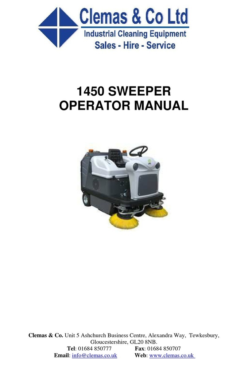
CS70 90B SWEEPER
OPERATOR MANUAL
Clemas & Co. Unit 5 Ashchurch Business Centre, Alexandra Way, Tewkesbury,
Gloucestershire, GL20 8NB.
Tel: 01684 850777 Fax: 01684 850707

INDEX
1. GENERAL INFORMATION pag.
1.1. Symbols…………….…………………….…….........................……......……………….. 4
1.2. Warning….................................................…………...…………..............…...…......... 4
1.3. Manual Consulting……….........…………………………....….........………….………… 4
1.4. Warranty..............................................................…………...…………...….…........... 4
1.5. Conformity Declaration…….........................................…...........………….…...……… 6
2. FEATURES AND TECHNICAL DATA OF THE MACHINE
2.1. Identifying the Machine……......…...............................….…………….….……........... 8
2.2. Description and Parts of the Machine……….…………………………….…….…........ 8
2.3. Technical Data………..................................…........……………………….....….......... 10
3. SAFETY
3.1. Right Use of the Machine……....……………....…....……………….....…………........ 12
3.2. Wrong Use of the Machine…….……………………………………………..………….. 12
3.3. Suggested Equipment………..…………………………………………………………… 12
3.4. Operator Qualify………...............……………….......……………...…………............... 13
3.5. Protection and Warning Devices……………………..................…...…………............ 13
3.6. Safety Devices……................................................…………..….…....…………........ 14
3.7. Other Dangers..………………………….…………………………………………………. 14
3.8. Safety Signals……………………….……………………………………………………... 15
4. STARTING AND USE INSTRUCTIONS
4.1. Trasport and Handling……....................….....................…....………….….….…........ 18
4.2. Storage……………...............................................…………….………….................... 19
4.3. Unpacking the Machine………………..........................……………………........…..... 19
4.4. Handling the Unpacked Machine….….….…..........………………………..…….......... 19
4.4.1 Battery version…………………....................................………………..……............. 19
4.4.2. Endothermic motor version.....……..….......……………….…...….….........…...... 20
4.5. Installation…………………………………………………………………………………… 20
Congratulations for your choice!
FIORENTINI S.r.l. thanking you for the preference to our product, would like to remind you that
FIORENTINI’s S.r.l production covers manufacture and marketing of industrial cleaning machines and
is currently a leading company in this sector.
Our tradition and competence guarantee technical quality of your choice; actually all our products are
being built first quality materials through criteria that can give reliability, solidity and functionality
satisfying every kind of customers. FIORENTINI has recently obtained the quality system certificate
conforming to the requirements of UNI EN ISO 9001:2000.
We wish therefore inviting you to contact us, unhesitatingly, for every kind of request, as technical or
commercial; we’ll be pleased to be at your disposal for any information you may need.


4.5.1. Battery installation………………………………………………………………………… 20
4.6. Control Devices…………………………………………………………………………….. 21
4.6.1. Dashboard……..…………………………………..…………………………………… 21
4.7. Functioning………………………………………………………………………………….. 23
4.7.1. Levers and Pedals…………….…………………………….…………………………. 23
4.7.2. Main Brush Replacement……………….………..………………………………..….. 24
4.7.3. Side Brush Replacement ……………………………………………………………… 25
4.7.4. Waste Tank Emptying (manual version)……..…………………………………….. 25
4.7.5. Waste Tank Emptying (automatic version)…..…………………………………….. 26
4.7.6. Suction Engine Maintenance……..…………………………………………………… 27
4.7.7. Filter Shaker Engine Maintenance…..……..………………………………………… 27
4.7.8. Petrol engine maintenance (endothermic motor version)………………………… 28
4.7.9. Controls for endothermic motor version……………………………………………… 29
5. MAINTENANCE
5.1. Maintenance Program……………..……………..................….....…..…………........... 30
5.2. Batteries Maintenance…………………………………………………………………….. 30
5.2.1. Hydrometry………..……………………………………………………………………. 31
5.2.2. Water Filling Up………………………………………………………………………... 31
5.2.3. Charge Limits…………………………………………………………………………… 31
5.2.4. Off duty or inactive batteries ……………..…………………………………………... 31
5.2.5. Batteries disposal ………..…………………………………………………………….. 31
5.3. Petrol engine maintenance (endothermic motor version)….…………………………. 32
5.3.1 Electric System Control…………………………………………………………………. 32
5.4. Tests to be carried out ……..…………………..………………………………………… 32
5.5. Maintenance Register…..…………………………………………………………………. 33
6. SERVICE
6.1 Adresses for technical assistance...........…………..................…………….................. 34
6.2. Claim Report……..……………………………..…………...………………….…............ 35

GENERAL INFORMATION UBF 28 NEW
Rev. 00 27/04/09 Pag. 7/36
DICHIARAZIONE CE DI CONFORMITA’
ING. O. FIORENTINI s.r.l.
Loc. Rombola
50030 PIANCALDOLI (FI) ITALIA
DICHIARIAMO SOTTO LA NOSTRA RESPONSABILITA’ CHE LA MACCHINA
Marca FIORENTINI
Tipo UBF 28 NEW
N° serie
Anno di costruzione 2009
RISULTA IN CONFORMITA’
con quanto previsto dalle seguenti direttive e normative armonizzate comunitarie:
DIRETTIVA COMUNITARIA
DIRETTIVA MACCHINE
98/37/CEE
DIRETTIVA BASSA TENSIONE
73/23/CEE
DIRETTIVA COMPATIBILITA’ ELETTROMAGNETICA
89/336/CEE
Ing. O. Fiorentini S.r.l.
Il titolare
Piancaldoli Ing. O. Fiorentini
Luogo e
data Firma

FEATURES AND TECHNICAL DATA OF THE MACHINE UBF 28 NEW
Rev. 00 27/04/09 Pag. 8/36
2. FEATURES AND TECHNICAL DATA OF THE MACHINE
2.1. IDENTIFYING THE MACHINE
A silver label is stuck on the metal sheet under the seat and clearly shows the data referring to the “CE”
brand.
The label has never to be removed and should always be kept readable. In case of
damage t is necessary to ask for a duplicate. The sweeper machine cannot be sold
without the label.
2.2. DESCRIPTION AND PARTS OF THE MACHINE
The machine UBF 28 NEW is designed for the treatment of flat surfaces through the process of brushing and
the following process of collection of dirt in a sharps container. The system of power is supplied by a series
of accumulators batteries (battery version), or a gasoli motor (endothermic motor version), which feed all the
motors and the electric control.
By means of a rotating brush set in front of the machine, the dust is put in the middle of the machine. The
main brush takes it into the waste tank. This machine must be used on dry or at least humid surfaces.
By means of the dashboard, the operator can control the functioning of the machine through a signalling
system made of LEDs. The dashboard is equipped with a battery charger indicator, too.
Functions of the machine which can be operated from the dashboard:
¾switch on /off the machine.
¾Activate the side brush
¾Activate the filter shaker
¾Activate the central roller brush
¾Activate the vacuum motor
Ing. O.Fiorentini S.r.l. MADE
50030 Piancaldoli (FI) IN
ITALY
Mod UBF 28 NEW S.N
V Hz
Kg A W
2
0
0
9
FIGURA N° 2.1

FEATURES AND TECHNICAL DATA OF THE MACHINE UBF 28 NEW
Rev. 00 27/04/09 Pag. 9/36
The machine frame is made of zinc-plated or stainless steel in order to avoid oxidation which could
compromise the reliability of the machine.
Following are the main components of the machine:
¾zinc-plated or stainless steel frame;
¾right side brush;
¾left side brush (optional)
¾main brush;
¾suction and collecting system;
¾driving wheel;
¾two idle wheels;
¾seat.
¾Discharge system (manual or automatic)
FIORENTINI Co., taking the new CE safety rules under consideration, manufactures the machine following
the CE directives about safety and health. The materials high quality, the high technology and FIORENTINI’s
experience guarantee the performance and the reliability of this machine .
Each machine is tested during the manufacturing process and the final check is done before the machine is
shipped out.

FEATURES AND TECHNICAL DATA OF THE MACHINE UBF 28 NEW
Rev. 00 27/04/09 Pag. 10/36
2.3. TECHNICAL DATA
UBF 28S NEW UBF 28 NEW
MAIN SPECIFICATIONS
SWEEPING WIDTH
•WITH 1 SIDE BRUSH
•WITH 2 SIDE BRUSHES 1100 mm 1100 mm
CLEANING CAPACITY UP TO 7150 m²/h 6050 m²/h
DIRTY CONTAINER CAPACITY 70 l 70 l
FILTERING SURFACE 6 m² 6 m²
GENERAL SPECIFICATIONS
TRACTION (ant/post) FRONT FRONT
KIND OF TRACTION HYDROSTATIC MOTOR-WHEEL
W/ELECTRO-BRAKE
FORWARDING SPEED 0/6.5 km/h 0-5.5 km/h
MAX. SLOPE 10 % 10 %
SOUND LEVEL (operator ear) 68 dB 50 dB
TURNING RADIUS 1330 mm 1330 mm
ELECTRIC SYSTEM
VOLTAGE / 24 V
VACUUM MOTOR / 24V/180W/3000 RPM
CENTRAL BRUSH MOTOR / 24V/650W/1800RPM/33A
SIDE BRUSH MOTOR / 24V/100W/90RPM/5A
TRACTION MOTOR / 24V/700W
FEEDING / 4 x 6V/320A/h
MOTORS (petrol version)
FEEDING PETROL /
MOTOR BRAND HONDA /
NO. CILINDRI 1 /
POWER 6 cv /
COLLING (AIR/WATER) AIR /
DIMENSIONS AND WEIGHT
LENGTH 1450 mm 1315 mm
WIDTH 870 mm 865 mm
HEIGTH 1260 mm 1235 mm
CENTRAL BRUSH Ø 265 x 700 mm Ø 265 x 700 mm
SIDE BRUSH Ø 400 mm Ø 400 mm
WEIGHT (empty machine) 336 kg 270 kg
BATTERY WEIGHT / 4 x 37 kg
OPTIONAL
DISCHARGING SYSTEM ELECTRO-HYDRAULIC ELECTRO-HYDRAULIC
DUMPING HEIGTH 1310 mm 1310 mm
The above mentioned characteristics are not binding for the manufacturer; they can be
changed without any notice . ING.O.FIORENTINI Co. is always at disposal for any
information (par.6.1.).

FEATURES AND TECHNICAL DATA OF THE MACHINE UBF 28 NEW
Rev. 00 27/04/09 Pag. 11/36
MEASUREMENT UNITS CONVERSION
Length 1 inch = 1” = 25,4 mm Power 1 kW = 1,36 CV = 1,34 BHP
Temperature T (K) = t (°C) + 273 / t (°F) = 1,8 t (°C) + 32 Pressure 1 bar =100 kPa = 14,5 psi

SAFETY UFB 28 NEW
Rev. 00 27/04/09 Pag. 12/36
3. SAFETY
3.1. RIGHT USE OF THE MACHINE
This sweeper has been designed for an industrial use. It can sweep on flat surface or
with a max. 10% slope.
3.2. WRONG USE OF THE MACHINE
¾the sweeper cannot be driven by non authorized personnel;
¾this machine cannot work on surfaces with holes;
¾this machine cannot sweep on sloping surfaces;
¾The machine cannot sweep sloping surfaces whose gradient is higher than 8%;
¾The machine cannot be used in places with dangerous substances and in
particular with explosive atmospheres or with a bad microclimate;
¾The machine cannot clean surfaces with inflammable products;
¾The machine cannot be used as a means of transport for people or other means
of transport;
¾The protection devices of the machine cannot be modified or tampered;
¾Batteries must be recharged in a fanned room;
¾The operator have always to respect safety rules;
¾The operator cannot use equipments or devices that can create problems to the
machine working;
¾The machine components cannot be modified without FIORENTINI’s
authorization;
¾The operator cannot use acids that can damage the machine;
¾The operator has always to respect the rules written in the user manual.
Please read carefully and do not cover the labels sticked on the machine. FIORENTINI
S.r.l. is not responsible for a wrong use of the machine.
3.3. SUGGESTED EQUIPMENT
In order to use the machine in a proper way, we suggest to use the FIORENTINI’s equipment and original
spare parts.
FIORENTINI S.r.l. Technical Dept. is always at your disposal to design components or parts for a particular
use of machine as requested by the customer.

SAFETY UFB 28 NEW
Rev. 00 27/04/09 Pag. 13/36
3.4. OPERATORS’ QUALIFY
The below specs shows the qualify requested from the operators depending on the kind of maintenance to
be done on the machine.
OPERATION OPERATORS’ QUALIFY
Driving/control of the machine Trained operator
Installation/ disinstallation Fiorentini technician
Mechanical parts maintenance Fiorentini technician
Electric parts maintenance Fiorentini technician
Cleaning maintenance Trained operator
Dismantling and demolition Fiorentini technician
FIORENTINI S.r.l. suggests to train the operator before using the machine. The operator also must be
trained about safety rules and carefully read this manual.
FIORENTINI S.r.l. is not responsible for any possible damage to people and/or things caused by
the non-observance of the instructions dealt within this manual.
3.5. PROTECTION AND WARNING DEVICES
•It is absolutely forbidden to tamper or disconnect safety and warning devices while
the machine is working;
•It is important to check periodically safety and warning devices
Central brush
protection
Fiorentini UBF 28 NEW is equipped with a central nylon brush which rotates
when the machine is working. The central brush is protected on both sides by
a stainless steel panel and two cases which avoid the contact with dangerous
components. These protection devices can be only willingly removed from the
machine.

STARTING AND USE INSTRUCTIONS UBF 28 NEW
Rev. 00 27/04/09 Pag. 14/36
3.6 SAFETY DEVICES
The machine is equipped with the following safety devices.
¾Socket (battery version) (picture 3.1), the same socket used for the battery charger. In case of
emergency, this socket must be taken away from the plug by means of its handle.
The operator must be trained about safety rules. Do never restore this safety system before the
problem has been sorted out. If it is necessary ask for the technician help.
¾Micro under seat (picture 3.1): under the operator seat there is a micro that prevent the machine
from working if the operator is not seat onboard. In the same way, if the operator lifts up without
switching off the motor, the machines stops automatically. To start the machine again, set the
ignition key to “off”, seat on the machine, then switch it on again.
3.7. OTHER DANGERS
FIORENTINI S.r.l. analyzes – starting from the design of the machine - all the dangers that can occur while
the machine is operating in order to prevent or at least low the operator’s accidents. Thanks to a series of
signals on the machine the operator can avoid many risks that can occur.
This kind of ranger can occur:
•during the brushes regulation;
•during the batteries/endothermic motor maintenance.
Whilst regulating the side brushes, the central brush and the central washing brushes, the ignition
key must be kept away from the dashboard in order to avoid the casual starting of the machine.
Whilst the batteries recharge, the operator must pay attention that any parts of his/her body enter the
batteries room.
Special labels stuck on the brush cover or on the recovery tank prevent dangers to the
operator (see § 3.7.).
SQUASHING DANGER
PICTURE 3.1

STARTING AND USE INSTRUCTIONS UBF 28 NEW
Rev. 00 27/04/09 Pag. 15/36
TURNOVER
This kind of ranger can occur:
- during the normal operating of the machine when you exceed sloping limits as specified in the
manual and you use the machine to clean disconnected surfaces or with holes and high
depressions.
Do not use the machine to wash sloping surfaces higher than 10% or surfaces with
holes or depressions which might compromise the stability of the machine.
FIORENTINI is not responsible for accidents occurred to people or things provoked by a
wrong use of the machine, i.e. using the machine on surfaces which can compromise its
stability.
The purchaser must stick proper labels on the machine to show the operator its right use.
3.8. SAFETY SIGNALS
Among safety signals there are:
DANGERS
Dangers’ signals are triangular with black
pictures on a yellow background
PROHIBITIONS
Prohibitions’ signals are round with black
pictures and a red stripe
What is it?
Crashing danger: it can be due to parts in movement of the machine.
What to do
During the installation or the maintenance make sure that the ignition
key is not in the dashboard before removing the mobile protections.
What is it?
This signal forbids to remove the protection of pieces in movement.
What to do
During the installation or the maintenance make sure that the ignition
key is not in the dashboard before removing the mobile protections.
While the machine is operating make sure that all covers are well
fixed.

STARTING AND USE INSTRUCTIONS UBF 28 NEW
Rev. 00 27/04/09 Pag. 16/36
The purchaser must replace danger signals on the machine if they are damaged. It is
absolutely forbidden to remove or temper danger signals.
Battery version:
What is it?
Risk of crashing due to overturning of the recovery tank.
What to do
Whilst recharging the batteries, please make sure that any parts of
your body got in contact with the batteries room.
What is it?
Explosion danger: it may occur while recharging the batteries because
of hydrogen spread.
What to do
During the batteries recharge, please place the machine under a
suction chimney or in a ventilated area and keep it away from heat
and corrosive substances.

STARTING AND USE INSTRUCTIONS UBF 28 NEW
Rev. 00 27/04/09 Pag. 17/36
The purchaser must replace danger signals on the machine if they are damaged. It is
absolutely forbidden to remove or temper danger signals.
Endothermic motor version:
What is it ?
This signal indicates the prohibition of removing protections of hot
parts when the machine is working.
What to do ?
Make sure that the machine is switched off and the key has been
disconnected from several minutes.
What is it ?
This signal indicates the danger of crashing due to closing of motor
cover or to the cooling fan when working.
What to do ?
During maintenance or controls please make sure that the key is
disconnected.

STARTING AND USE INSTRUCTIONS UBF 28 NEW
Rev. 00 27/04/09 Pag. 18/36
4. STARTING AND USE INSTRUCTIONS
4.1. TRANSPORT AND HANDLING
The machine is delivered to the purchaser in a proper package (see picture 4.1 below). A black arrow on the
package indicates the barycentre. This arrow must be in the middle of the elevator or transpallet forks. The
package must be carefully handled. Do not place one package on another one. If agreed with the purchaser,
the machine can be delivered without package, placed on a pallet and fixed by means of straps.
The purchaser must make sure that the machine has not been damaged during the
transport and that all papers are on the machine. Otherwise, the purchaser must
immediately contact FIORENTINI in order to sort out the problem.
The purchaser is responsible for the transport of the machine if not differently agreed with
FIORENTINI.
The machine must be handled with proper devices as stated in the scheme below.
Make always sure that the black arrow on the package is in the middle of the elevator forks or the straps.
Anchorage and/or strapping points are set up in order to keep the machine on balance during the transport.
PACKAGE HANDLING EQUIPMENT PIC.
Carton box or plywood box on a
pallet Fork elevator Nr. 4.2
Ø
PICTURE 4.1

STARTING AND USE INSTRUCTIONS UBF 28 NEW
Rev. 00 27/04/09 Pag. 19/36
Bands used for lifting the machine up must have the same loading capacity as the
machine load. Handling operations must be done without causing a loss of stability
of the machine. Otherwise, the machine can be damaged or the operator can de in
danger.
FIORENTINI suggest to use authorized personnel (see § 2.3.) to handle the machine.
LOADING SYSTEM
4.2. STORAGE
The machine must be stored in a closed and dry place if not immediately installed in order to keep every part
safe.
Relative humidity must be lower than 80% and the storage temperature must be between 3°C ≤t ≤+ 45 °C.
4.3. HOW TO UNPACK THE MACHINE
¾Cut the straps paying attention to the back spring.
¾Remove clips that join pallet and carton;
¾in case of plywood box, please remove clips from both sides and basis of each panel:
¾Cut the strips that hold the machine.
¾Lay the machine on the floor.
4.4 HANDLING THE UNPACKED MACHINE
4.4.1 Battery version machine:
¾Check the machine and install the batteries if not already installed.
¾For a brief transport of the machine, please disconnect the batteries cables and remove brushes; for
a longer transport, please use the original package of the machine.
PICTURE N° 4.2

STARTING AND USE INSTRUCTIONS UBF 28 NEW
Rev. 00 27/04/09 Pag. 20/36
4.4.2 Endothermic motor version:
¾Check the machine and especially the motor, paying attention to the level of oil and cooling liquid.
¾Fill the machine with fuel
¾For a short transport of the machine empty the fuel tank and remove the brushes. For a longer
transport, please use the original package of the machine.
4.5. INSTALLATION
Installation must be carried out by authorized personnel after reading this manual..
4.5.1 BATTERIES INSTALLATION (BATTERY VERSION MACHINE):
Please follow the instructions below to install the batteries:
¾the batteries room is under the operator’s seat protected by a cover;
¾lift the cover of the batteries room up (picture no. 4.4 detail 1);
¾install the batteries in their room (picture 4.4 detail 2) and make sure the batteries boxes are not
broken;
¾do never add distilled water after batteries recharge;
¾clean the surfaces for the cables connections;
¾use the handles on the batteries to move them.
PICTURE N° 4.4
12

STARTING AND USE INSTRUCTIONS UBF 28 NEW
Rev. 00 27/04/09 Pag. 21/36
4.6. CONTROL DEVICES
4.6.1. DASHBOARD
The dashboard is made of a series of switches that activate or disactivate all the machine functions. The
function of each switch is shown by a picture. Picture 4.6. shows the dashboard of the machine and the
switches function is explained in the scheme in the following page.
POS. PICTURE FUNCTION
1
SIDE BRUSH ACTIVATION
2
BATTERY CHARGE INDICATOR (BATTERY VERSION)
3
MOTOR PROTECTOR
4
KEY SWITCH (BATTERY VERSION)
PICTURE N° 4.6
3
4
5
6
7 8 9
1
2

STARTING AND USE INSTRUCTIONS UBF 28 NEW
Rev. 00 27/04/09 Pag. 22/36
POS. PICTURE FUNCTION
5
KEY SWITCH (ENDOTHERMIC MOTOR VERSION)
6
HORN
7
VACUUM ACTIVATION OF DUST COLLECTOR AND FILTER SHAKER
8 CENTRAL BRUSH ACTIVATION
9
LIFT UP/DOWN OF DUST COLLECTOR
(VERSION WITH AUTOMATIC DISCHARGE)

STARTING AND USE INSTRUCTIONS UBF 28 NEW
Rev. 00 27/04/09 Pag. 23/36
4.7. FUNCTIONING
Switch the sweeper on and start both the side brush and the central brush by means of the levers. Then start
the suction engine which intake and collect the rubbish into the recovery tank. The brushes start working by
means of the accelerator lever. Drive the machine with a regular speed during the sweeping process.
Do always keep the suction engine clean from dust. As a consequence, the filter is always clean and can
work properly.
Before any operation, make sure that all protections are well fixed.
4.7.1 LEVERS AND PEDALS FUNCTIONING
This machine is equipped with following levers:
¾accelerator lever (picture 4.7 detail 1): select forward gear by means of the lever on the operator’s
right hand. Select reverse speed by means of the lever on the operator’s left hand.
The accelerator lever start all the mobile parts of the UBF28 NEW. Therefore, brushes work
only after having started the lever.
¾side brush lever (picture 4.7 detail 2): push the lever down and the side brush goes down onto the
floor;
¾flap lifting pedal (picture 4.7 detail 3)
¾central brush lever (picture 4.7 detail 4): push the lever down and the central brush goes down onto
the floor; pull the lever to put the brush in its original position.
¾Endothermic motor version: parking brake (detail 5). With this pedal it is possible to slow down the
machine till complete stop. This pedal works also as parking/emergency brake.
In the battery version machine, the electrobrake works on the front wheel stopping the machine
when the forward pedal is released
PICTURE N° 4.7
4
2
5
3
1
Table of contents
Other Clemas & Co Blower manuals

Clemas & Co
Clemas & Co S9 User manual

Clemas & Co
Clemas & Co 512 User manual

Clemas & Co
Clemas & Co GANSOW 125 User manual

Clemas & Co
Clemas & Co 1010 User manual

Clemas & Co
Clemas & Co CS230 145B User manual

Clemas & Co
Clemas & Co 1450 User manual

Clemas & Co
Clemas & Co CS220 140B User manual

Clemas & Co
Clemas & Co S3 User manual

Clemas & Co
Clemas & Co S9 User manual