CLEOPATRA Sedna Line Quick start guide

Steam Baths Professional
Sedna Line
A. 90548801 R01
2008/05
lnstallan and use
EN

Contents
For the installer:
For the user:
Section Page

Pos Article Description
MODEL 1
MODEL 2
MODEL 3
MODEL 4
MODEL 5
MODEL 6
MODEL 7
MODEL 8
MODEL 9
MODEL 10
MODEL 11
MODEL 12
MODEL 13
MODEL 14
MODEL 15
MODEL 16
119337800 Corner element left 0 0 1 1 1 1 1 1 1 2 1 1 1 1 2 2
219337700 Corner element right 0 0 1 1 1 1 1 1 1 2 1 1 1 1 2 2
319338000 Seat element 1500mm 1 2 0 0 0 1 2 2 2 0 3 2 2 2 0 0
419337900 Seat element 750mm 0 0 0 1 2 1 0 1 1 0 1 2 3 3 2 2
519591000 Roof element Sloping 1500 x 750 2 0 0 0 0 0 0 0 0 0 0 0 0 0 0 0
619509500 Roof element Sloping 2250 x 750 0 2 2 2 2 2 2 2 2 2 2 2 2 2 2 2
719509600 Roof element Concave 2250 x 750 0 0 1 1 2 2 3 3 3 3 4 4 4 4 4 4
830522610 Roof element with ventilating unit 1 1 1 1 1 1 2 2 2 2 2 2 2 2 2 2
919576980 Frame Wall 6 8 10 10 12 12 14 14 14 14 16 16 16 16 16 16
10 19590480 Frame wall rarrow (with 1m door) 2 2 2 2 2 2 2 2 2 x x x
11 19576880 Frame seat element
12 19577980 Steam module with frame 1 1 1 1 1 1 1 1 1 1 1 1 1 1 1 1
13 Reducer ventilating unit 1 1 1 1 1 1 2 2 2 2 2 2 2 2 2 2
14 19578210 Wall panel 12 14 15 14 17 16 19 18 18 17 20 21 20 24 18 18
15 19578220 Wall panel steam module 1 1 1 1 1 1 1 1 1 1 1 1 1 1 1 1
16 19337310 Corner glass plate 0 0 2 2 2 2 2 2 2 4 2 2 2 2 4 4
17 19579810 Steam glass plate 1 1 1 1 1 1 1 1 1 1 1 1 1 1 1 1
18 30949610 Wall fastening 4 4 12 12 12 12 12 12 12 20 12 12 12 12 20 20
19 19578680 Corner piece 35x35 0 0 12 6 12 6 12 6 6 12 6 12 6 6 12 12
20 19578780 Corner piece 35x57 6 6 0 3 0 3 0 3 3 0 3 0 3 3 0 0
21 19578880 Corner piece 57x35 6 6 0 3 0 3 0 3 3 0 3 0 3 3 0 0
22 90080682 Hexagonal socket bolt M8x12 14 14 14 14 14 14 14 14 14 14 14 14 14 14 14 14
23 90003780 Hexagonal tap bolt M8x30 50 50 70 70 90 90 110 110 110 110 130 130 130 130 130 130
24 19590800 Shims 1mm thick 5 5 10 10 15 15 15 20 20 20 20 20 20 20 20 20
25 19590900 Shims 3mm thick 5 5 10 10 15 15 15 20 20 20 20 20 20 20 20 20
26 90054082 Hexagonal nut M8 50 50 70 70 90 90 110 110 110 110 130 130 130 130 130 130
27 90056180 Bodywork ring M8 100 100 140 140 180 180 220 220 220 220 260 260 260 260 260 260
28 90040680 Coach screw 8 x 50 18 18 22 22 26 26 30 30 30 30 34 34 34 34 34 34
29 90014502 Plug D10 x 50 18 18 22 22 26 26 30 30 30 30 34 34 34 34 34 34
30 52860038 Polymer cement 3 6 7 7 9 9 10 10 10 10 12 12 12 12 12 12
31
32 90019210 Drill point screw D3.9 x 25 185 185 210 210 235 235 260 260 260 260 285 285 285 285 285 285
33 90011580 Drill point screw with hexagonal head D4.2 x 25 6 6 6 6 6 6 6 6 6 6 6 6 6 6 6 6
34 30930210 Door (M1) Left 750mm 1 1 1 1 1 1 1 1 1 1 1 1 1 1 1 1
35 30930211 Door (M1) Right 750mm 1 1 1 1 1 1 1 1 1 1 1 1 1 1 1 1
36 Door (M1) Left 1000mm 1 1 1 1 1 1 1 1 1 1 1 1 1 1 1 1
37 Door (M1) Right 1000mm 1 1 1 1 1 1 1 1 1 1 1 1 1 1 1 1
38 19578310 Top bar 750mm 1 1 1 1 1 1 1 1 1 1 1 1 1 1 1 1
39 19578320 Top bar 1000mm 1 1 1 1 1 1 1 1 1 1 1 1 1 1 1 1
40 30955700 Handle complete 1 1 1 1 1 1 1 1 1 1 1 1 1 1 1 1

1 Scope of delive
ACRYLIC
3
1
8
FMES
®
STEAM INLET
MFDU
WALL PANELS
2

1 Scope of delive
GLASS PLATE
17
\
CORNER ASSEMBLY
19
20
21
0
ASSEMBLY MATERIAL
22
21 �
© '
29
®
DOOR
®@
ten/ 1ooom
3

1 Scope of delive
40
$
I
@
DOOR
0 0
.
$
I
@
.
4

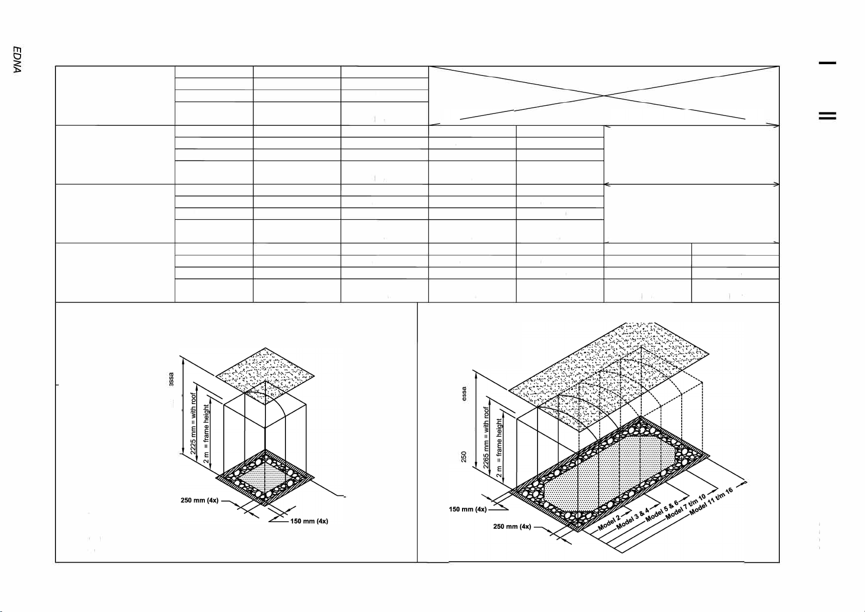
2 Installation dimensions
•
*minimum required fitting space
�
Vmln
f
�
f
r :
5
0
0
GROUP1
GROUP2
GROUP3
GROUP4
Model 1
"
E
II�
0
0
3 3
2 2
2 2
3 3
2 2
2 2
3 3
2 2
2 2
3 3
2 2
2 2
Model 1
3 3
2 2
2 2
3 3
2 2
2 2
3 3
2 2
2 2
Model 2 m 16
�
0
-
3 3
2 2
2 2
0
-·
3
0

3 Basis
3.1 U-setup for the frames
Figure 1
-
Detail C
I
I
I
'
'
(
�
Side A
I
(
\
Side B
A-side B-side
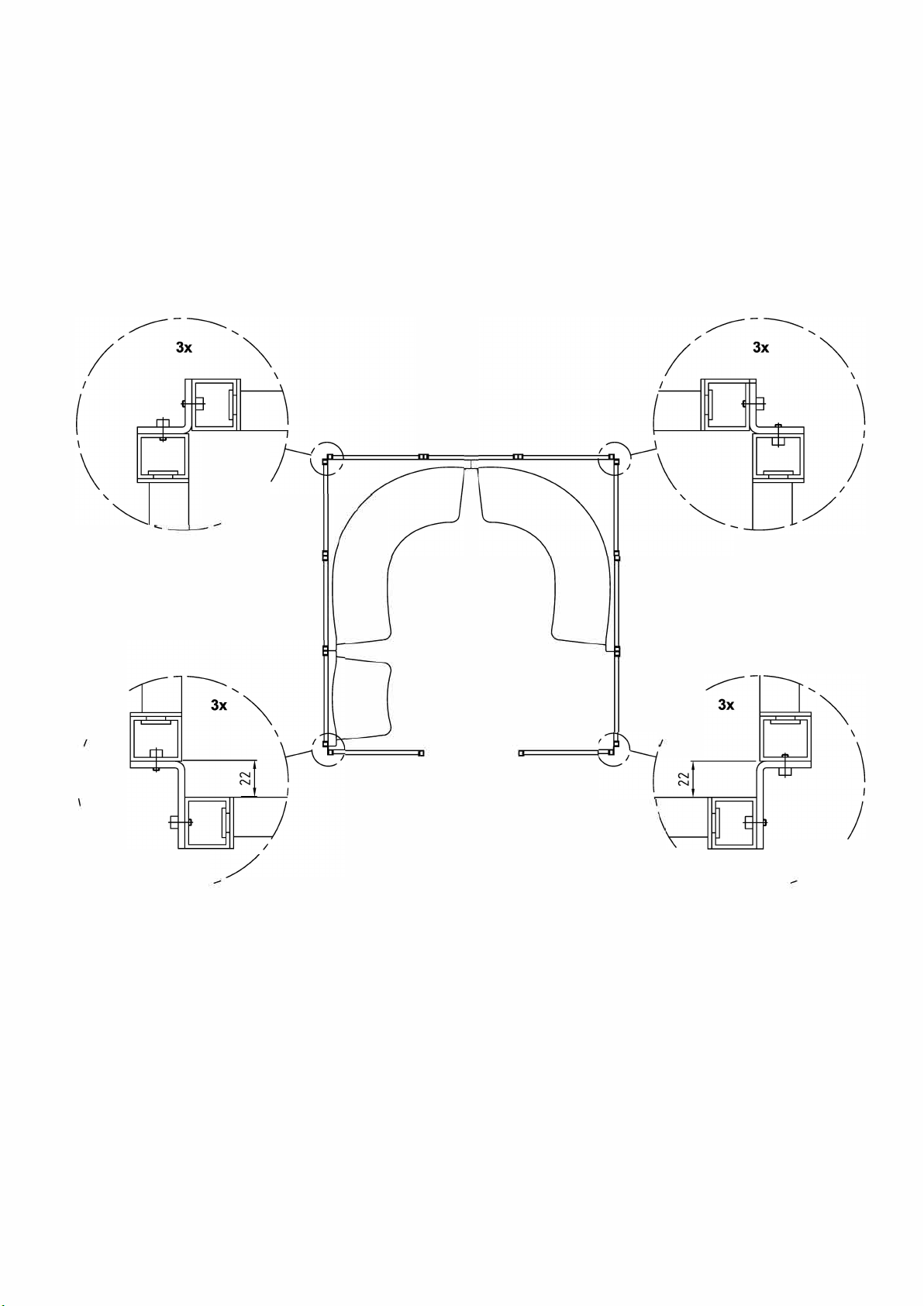
3 Basis
3.1 U-setup for the frames
Corner pieces
(Cabin model 4 serves as example)
I
(
'
/
�
I
/
Corner piece 35x35
Corner piece 35x57 with
threaded hole on short side
/
I
'
Corner piece 35x35
I
� /
Corner piece 35x57 with
threaded hole on long side
2) Where frame parts are joined to each other with a corner piece care must be taken with the choice of corner piece.
This depends on the situation (fig.2). Details and show the situation at a corner seat In all other situations corner
pieces are used as shown in detail F and G.
Exceptions are models 3, 5, 7 and 12. Here the situation in all corners is the same as detail D and E.
The assembly of the corner pieces takes place with the same hexagon socket bolts M8x12 with which the frames are
connected to each other.
8

3 Basis
3.1 U-setup for the frames
Figure 3a
Figure 4
0
Figure 3b
Figure 3c
3)

3 Basis
3.2 Aligning the U-setup
Figure 1
Aligning
Detail A
Fixing to the floor
(Cabin model 4 serves as example)
4)
5)
D
Chalk line
Check whether distances B, C and D are equal to distance A (fig. 1 ). The most accurate way is not to measure this
distance between the adjustable legs but between the bottoms of the frames (approx. 12 cm above floor level).
If necessary temporarily fix this distance with a wooden slat fixed to the frame using glueing clamps.
Now measure both diagonals E/F (approx. 12 cm above floor level). These must be equal (walls are then perpendicular
to each other).
Check the frame both horizontally and vertically with a long (min. 1 m) spirit level as described. If necessary adjust the
adjustable legs.
When the frame is aligned the legs can be screwed tight to the floor (detail A). To do this use a 10 mm bit to drill through
the holes in the legs through to the floor.
Note: there may be no undeloor heating in the area to be drilled!
Fit the plugs (diameter 1 0x50) and screw the legs tight to the floor with the coach bolt 8x50.
If the floor cannot be drilled into, the frame can be adhered to the floor with polymer cement.
Make sure that the frame parts are correctly positioned and that they cannot move during the drying time of at least 8
hours.
Use glueing clamps or other means to temporarily fix the frame as necessary.
With large cabins it is advisable when fitting the roof elements to use the slats and glueing clamps mentioned in point 4
to prevent the parallel sides of the U-setup from moving out of line while fitting the roof elements.
10

3 Basis
3.3 Connecting the roof elements to each other
Figure 1
I
I
I
'
Detail A
I
I
J
1)
2)
3)
3 Basis
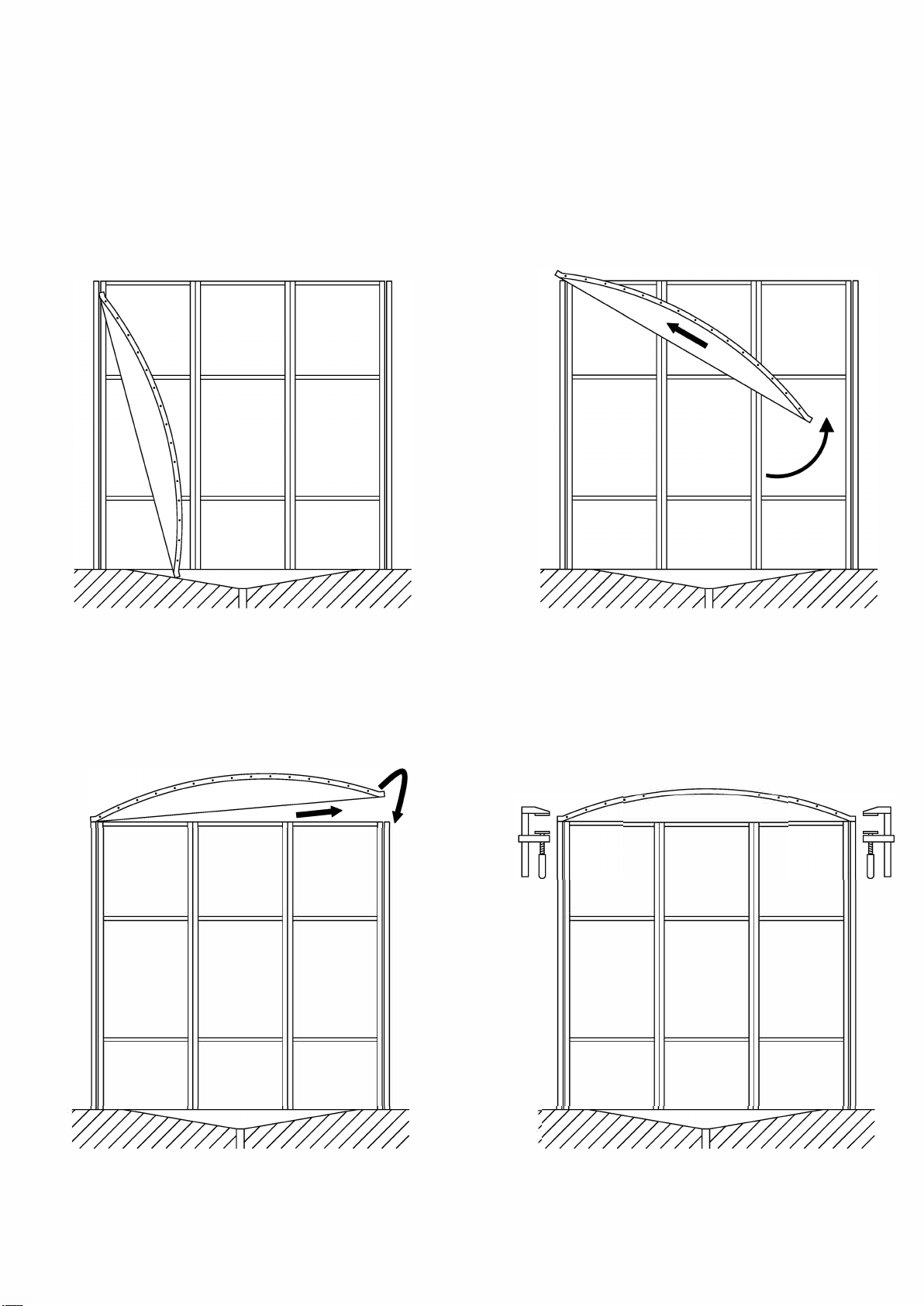
3.4.1 Fitting the roof on the U-setup
Figure 1
Staing position
Step 2.
Step 1.
. . . . .
Step 3.
3 Basis
3.4.2 Fitting te roof on the U-setup
Alternative method
Figure 2
======
-
l -
:
-
======

3 Basis
3.5 Fitting M1 door
\
Figure 1 Figure 2
Detail A
-
E
E
Detail B
Figure 3
1)
14

3 Basis
3.5 Fitting M1 door
Figure 4
Top view
Cabin model 1
Figure 5
Detail C
Detail D
\
' -Self-tapping screw
� /
-
Detail E
3)
Note! To prevent damage to casing and hinges the assembly of a door stopper is required. This is not
included in the delivery.

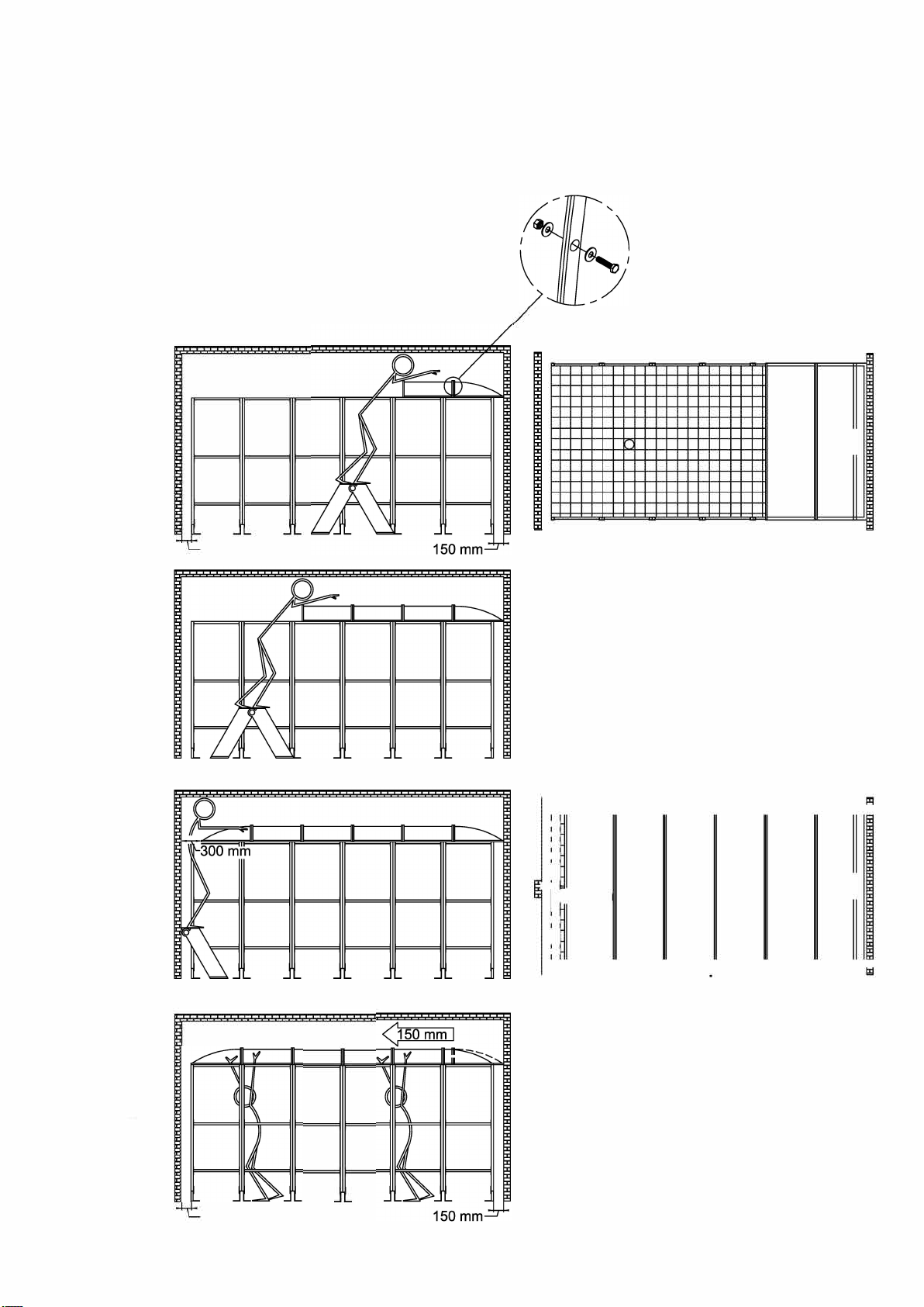
3 Basis
3.6 Finishing the roof
Figure 1
Figure 2
to outside air
-
Figure 3
1)
2)
3)

3 Basis
3.7 Assembly of bar with steam inlet
Figure 1
Figure 2
1)
2)
3)
4)
5)
6)

4 Seat elements
Figure 1
Figure 2
Detail A
'
10-20mm
Figure 3
1)
2)
3)
4)
5)
6)
18
Table of contents
Other CLEOPATRA Bathtub manuals


Popular Bathtub manuals by other brands

Kohler
Kohler Freewill K-12105-H installation instructions

Artweger
Artweger TWINLINE 1 AIR mechanical manual

American Standard
American Standard Cadet Whirlpool/Bathing Pool 2772.XXXW installation instructions

GALA
GALA mitta user manual

Kohler
Kohler K-1457-G Roughing-In Guide

Jacuzzi
Jacuzzi Arga Preinstallation manual

Jacuzzi
Jacuzzi ARGA 175x85 Instructions for preinstallation

Jacuzzi
Jacuzzi Stella Installation and operation instructions

Kohler
Kohler LOVEE K-9289T installation instructions

Casabath
Casabath MY SPACE installation instructions

Porcelanosa
Porcelanosa KRION PURE installation guide

GoodHome
GoodHome 5059340060095 manual


