Clesana C1 Series User manual

5/324/32
Contents
....................................................................................................................................................................................6
1.1. About this manual.....................................................................................................................................................6
1.2. Symbols................................................................................................................................................................................6
2. Safety.......................................................................................................................................................................................................7
2.1. Proper use ........................................................................................................................................................................7
....................................................................................................................................................................7
.................................................................7
..................................................................................................................................................................7
.....................................................................................................................................................7
2.4.2 Fire hazard............................................................................................................................................................8
2.4.3 Component damage due to short circuit ..............................................................................8
2.4.4 Moving parts......................................................................................................................................................8
2.4.5 Water damages...............................................................................................................................................8
2.4.6 Health hazards from contaminated water...........................................................................8
3. Delivery scope................................................................................................................................................................................9
4. Tools and consumables .........................................................................................................................................................9
5. Overview.......................................................................................................................................................................................... 10
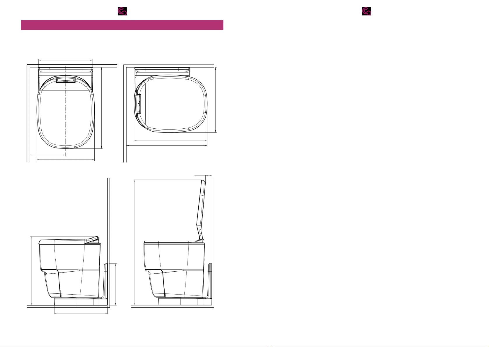
5.1. Measurements Clesana C1 with L-Adapter.................................................................................. 10
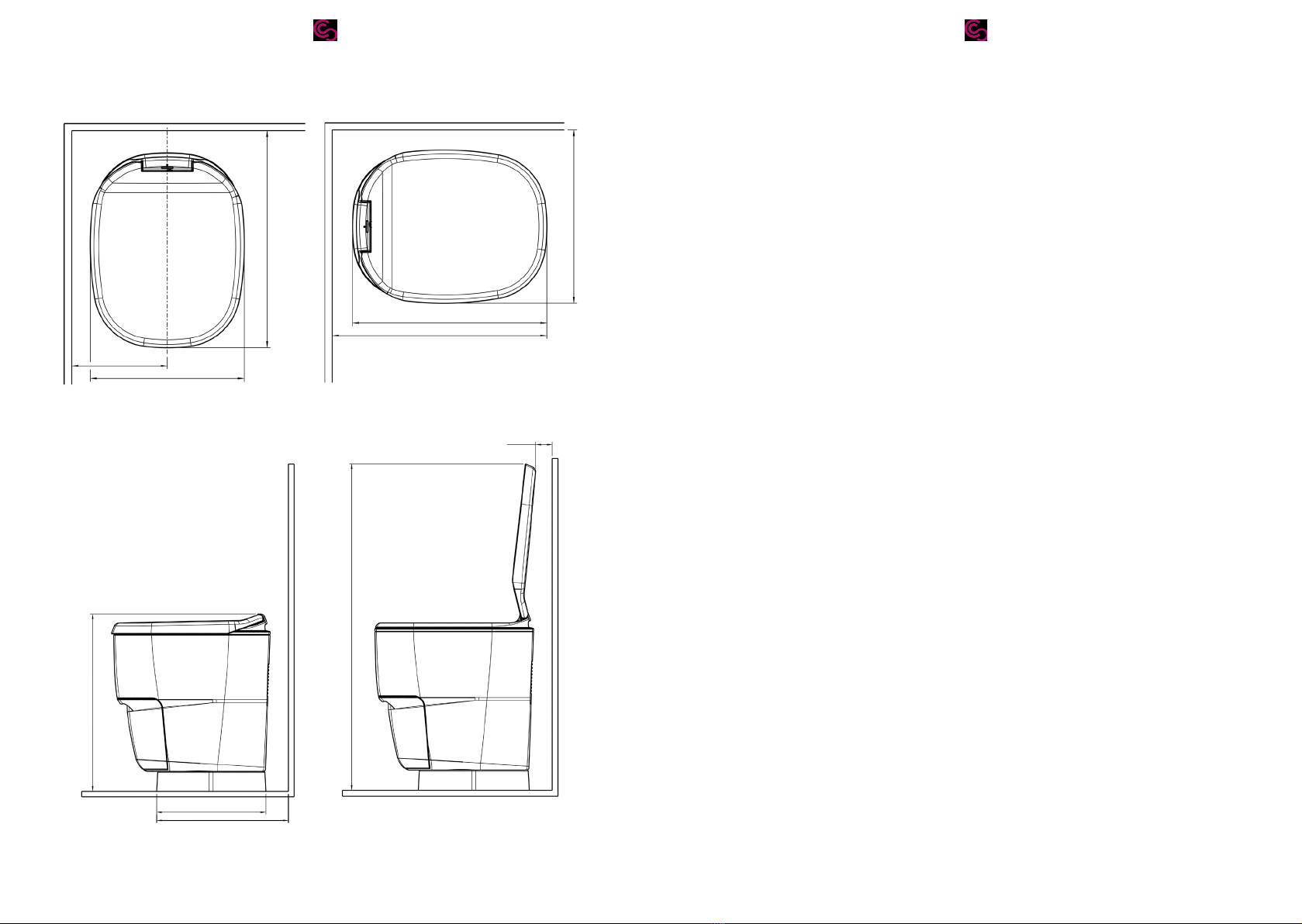
5.2. Measurements Clesana C1 with round base .............................................................................. 12
.................................................................................................................................................................................... 14
6.1. First steps ....................................................................................................................................................................... 14
.............................................................................................................. 14
....................................................................................................................... 15
6.4. Prepare L-Adapter or round base........................................................................................................... 15
............................................................................................................................................................ 17
7.1. Overview......................................................................................................................................................................... 17
......................................................................................................... 19
8. Install the L-Adapter............................................................................................................................................................. 20
........................................................................................................... 20
8.2. Screw the L-Adapter to the wall.............................................................................................................. 21
......................................................................................................................................................... 22
9. Install the round base......................................................................................................................................................... 23
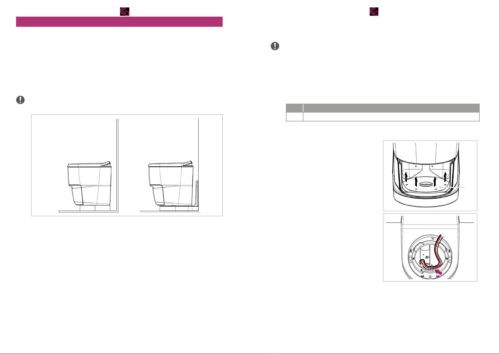
9.1. Prepare the round base................................................................................................................................... 23
9.2. Mount the round base...................................................................................................................................... 23
10. Install the control panel.................................................................................................................................................... 25
......................................................................................................................................................... 25
........................................................................................................................................................... 26
................................................................................................................................. 28
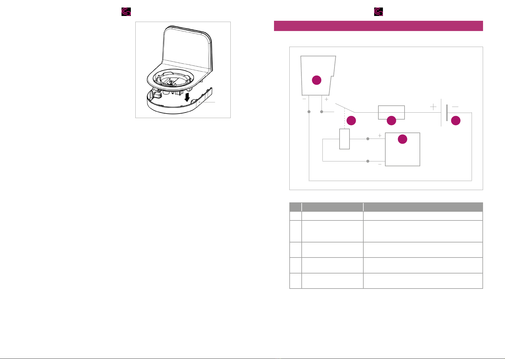
11.1. Connect the Clesana C1................................................................................................................................... 28
................................................................................................................................................ 28
................................................................................................................................................... 29

7/326/32
1.
1.1. About this manual
X
X
on our website whether a newer version of this
manual is available.
1.2. Symbols
Symbol Meaning
processes
X
ª
Important details in graphics
2. Safety
2.1. Proper use
The waterless toilet Clesana C1 is used for sanitary bagging of excrements and personal
2.2. Qualicaon
persons trained and authorised for this purpose.
-
X
X
X
2.3. Technical condion, modicaons and spare parts
X
X
X Do not modify the toilet and its parts.
X Use only original parts and materials approved by Clesana.
2.4. Residual risks
2.4.1 Electric shock
X
the electrical engineering rules:
– Disconnect power supply.
–
– Earth and short-circuit.
X
2.4.2 Fire hazard
-
can result in property damage and personal injury.

9/328/32
X
– up to 8 m: 10 mm²
– from 8 m: 16 mm²
X
on the power supply.
X Do not clamp or excessively bend the cables.
2.4.3 Component damage due to short circuit
Reversing the polarity of the power cable can damage the electrical components. A
X Ensure the correct polarity of the power cable before switching on the power
supply.
2.4.4 Moving parts
X Keep the surroundings of the toilet free of objects.
2.4.5 Water damages
dismantled. Faulty sealing of the water line can result in water damages in the vehicle.
X
X
X Ensure correct sealing of the L-Adapter.
2.4.6 Health hazards from contaminated water
X
e.g. on a manifold or a T-piece.
X Ensure that the shut-down water line does not allow any standing water in the line.
3. Delivery scope
No. Part
1 Base body Clesana C1
1 L-Adapter or round base
1 Control panel with cable
2
1
1
1
1
Barrier foil liner not included in the scope of delivery.
X
4.
No. Tools
1 Screwdriver Torx TX20
1 Wood drill Ø 4.5 mm
1
Wood drill Ø 16 mm
1
1 Press tool for cable lug and connector
No. Installaon material
1
—
— Ring cable lug
— Cable strap
3 Wood screw half-round head/plate head Ø 4.5 mm
4
Wood screw half-round head/plate head Ø 4.5 mm
5

11/3210/32
5. Overview
5.1. Measurements Clesana C1 with L-Adapter
Main dimensions
341 mm
514 mm
363 mm
509 mm
461 mm
412 mm
935 mm
48 mm
515 mm
312 mm
397 mm
Rotang the toilet
Max. 90° Max. 90°
Bracket: Floor - wall
90° ±0.5

13/3212/32
5.2. Measurements Clesana C1 with round base
Main dimensions
363 mm
509 mm
461 mm
407 mm
42 mm
317 mm
378 mm
515 mm
935 mm
Rotang the toilet
Max. 90° Max. 90°

15/3214/32
6.
6.1. First steps
X
X Have tools and consumables ready.
6.2. Choose the installaon locaon
The Clesana C1 can be installed both with the round base and with the L-Adapter. The
clesana.com/info-area-
A B
Fig. 1:
X Using the measurements of the Clesana C1 ensure the following points on the
–
its own weight.
–
–
6.3. Dismantle the exisng toilet
1.
-
nector. A plug specially provided for this purpose can be used for a distributor.
2.
3. Ensure that the shut-down water line does not allow any standing water in the line.
4.
6.4. Prepare L-Adapter or round base
No. Tools and consumables
1 Screwdriver Torx TX20
1. -
2. 4 × Loosen the screws with screwdriver
discs (1).
1
3. Loosen the exposed cable from the
cable duct of the L-Adapter or the
round base.
4.
cm and remove from the L-Adapter or
round base.

17/3216/32
5. If the toilet is installed in a shower
L-Adapter.
2
7.
7.1. Overview
EBL
30 A
C1
1
43
2
5
Fig. 2:
No. Descripon Funcon
1 Clesana C1 User
2 • -
cal system
• Controls the relay.
3 Fuse 30A Interrupts the circuit in case of overload or short
circuit
4
Living space power supply
5 Relay

19/3218/32
Specicaons
Specicaon Value
(the power supply must ensure 22A at rated voltage)
2-pin connector housing
lines in the connector
housing
the toilet
Anderson SB50 connector housing 992G1
Crimp contact Anderson SB50 50 Amp Contact 5952
Cable diameter up to 8 m: 10 mm²
from 8 m: 16 mm²
Relay
7.2. Perform the electrical installaon
No. Tools and consumables
1
1 Press tool for cable lug and connector
—
— Cable strap
—
— Ring cable lug
1 Relay
1.
2.
3.
4.
ring cable lug.
5.
access to the relay.
6. Connect the relay with the power
+
+
Clesana C1
–
EBL
+
EBL
7. Crimp the ends of the power cable to
the Clesana C1 with crimp contacts
Anderson SB50 and route in the con-
nector housing Anderson SB50.

21/3220/32
8. Install the L-Adapter
8.1. Screw the L-Adapter on the oor
ø8.1
ø4.4
3
Fig. 3:
No. Tools and consumables
1 Screwdriver
5
1. Align the L-Adapter to the wall.
2.
8.2. Screw the L-Adapter to the wall
143 mm
145 mm 145 mm
294 mm
ø 4.5 mm
Fig. 4: Bores for screwing on the wall
No. Tools and consumables
1 Wood drill Ø 4.5 mm
1 Screwdriver
3 Wood screw half-round head/plate head Ø 4.5 mm
1. Bore 3 holes in the wall according to
the template.
2. Choose the length of the wood screws
mm.
3.
bore holes.
4. Screw 3 wood screws from behind
5.
lip of the L-Adapter with the wall.
27

23/3222/32
8.3. Finishing works
1. Pull the power cable and the control
cable for the control panel into the
L-Adapter from behind.
2. Place the base body on the L-Adapter.
9. Install the round base
9.1. Prepare the round base
1.
2. Pull the ends of the power cable and
the control cable for the control panel
through the opening into the round
base.
9.2. Mount the round base
ø 4.4
3
ø 8.1
Fig. 5:
No. Tools and consumables
1 Screwdriver
5
1.
2.

25/3224/32
3. Place the round base on the L-Adapter.
10. Install the control panel
10.1. Flush mounng
128 mm
85 mm
36.3 mm
114 mm
72.9 mm
69 mm
1.8 mm
Fig. 6: Control panel measurements
wall to install the control panel.
1.
points:
– The display is clearly legible.
– The control panel can be easily operated.
–
– The distances between the control panel and the L-Adapter is smaller than the
116 mm
72.5 mm
max. R5
Fig. 7:
2. Create the wall opening according to the dimensions in the Fig. 7.
3. Lay the cable ends from L-Adapter or round base to the control panel.

27/3226/32
4.
5.
10.2. Wall mounng
128 mm
85 mm
ø 4.5 mm
Hole in the wall
min. ø 16 mm
4 mm 41.6 mm
Fig. 8: Measurements of the wall-mounted housing
the housing yourself. The design data (CAD and design drawings) are available in the
dealer area .
No. Tools and consumables
1 Wood drill Ø 16 mm
1 Screwdriver
4 Wood screw half-round head/plate head Ø 4.5 mm
1.
following points:
– The display is clearly legible.
– The control panel can be easily operated.
– The distances between the control panel and the L-Adapter is smaller than the
2.
3. Lay the cable ends from L-Adapter or round base to the control panel.
4.
5.
6.

29/3228/32
11.
11.1. Connect the Clesana C1
No. Tools and consumables
1 Screwdriver Torx TX20
1. Connect the control cable of the control
panel with the control cable from the
base body.
2. Connect the power cable coming from
of the base body.
3. Snap the housing plug (red) into the
4. Lay the power and control cable in the
5.
with 4 x screws and screwdriver Torx
TX20.
6.
7. Put on the lid unit.
1
11.2. Check the funcon
1.
– Clesana C1 can be rotated.
–
– The tray snaps into place upon closing.
–
2. Switch on the voltage.
ªStart the Clesana C1.
3.
4.
12.
Characterisc Value Unit
Height
Width
L-Adapter/round base length
515
363
516/461
mm
mm
mm
Seat height 478 mm
Weight of C1 with L-Adapter/with round
base
13.8/13.1
Supply voltage 11.8–15 V
Rated voltage 12 V
22 A
0.28 W
265 W
1.7 ±0.17 Wh
0.55 ±0.06 Wh
Usage temperature 5–40 °C
—

Declaraon of conformity
Manufacturer: Clesana AG
Werdenstrasse 72
9472 Grabs
Switzerland
hereby declares that the following product
Waterless toilet
Clesana C1 Series
based on the following applied standard:
•
• 2011/65/EU RoHS 2
•
Signature
Placer, date

clesana.com
Other manuals for C1 Series
1
Table of contents
Other Clesana Toilet manuals
Popular Toilet manuals by other brands

Lippert
Lippert Flow Max 2022113192 Installation and owner's manual

Uberhaus
Uberhaus 06115004 Installation instruction

VIGOUR
VIGOUR derby AQUAWASH installation manual

Franke
Franke HDTX0020 Installation and operating instructions

Victorian Plumbing
Victorian Plumbing ME90103 Installation and Utilization Instructions

Vetus
Vetus HATO212B Installation instructions and operation manual