ITT Industries JABSCO 37275 Series User manual

Model: 37275-Series
DESIGNER STYLED MARINE
TOILET
FEATURES
• Very quiet flush cycle —like a household toilet
• Single button flush actuator—with dual function water
level control switch
• Supplied with Par-Max 4 self-priming pump to provide
sea water or lake water to rinse the toilet bowl
• Vitreous china bowl available in compact 14"height
or standard 17"height
• Available in White or Bone
• Baked enamel seat & cover
• High capacity waste macerator and bowl discharge
pump
• All toilet plumbing and wiring connections are
internal-out of sight
SPECIFICATIONS
Ports: PAR-MAX Pump and Toilet
Inlet—3/4"Hose Barb
Outlet—1"Hose Barb
Motor & Switch: Pump and Toilet Meet U.S.C.G.
Regulation 183.410 and
ISO 8846 Marine for
Ignition Protection.
Toilets are marked and
comply with EN50081-1
for suppression of electro-
magnetic interference.
Normal Water 1-2 Quarts (Litres)/Flush
Consumption:
OPERATION
The Designer Styled Toilets with the popular Quiet-Flush
system provide both quiet operation and user control of
water levels in the toilet bowl. A single large push-button
switch provides a simple flush mode by activating both the
rinse water supply and the macerator discharge pump
simultaneously. An additional rocker switch offers inde-
pendent control of the rinse water supply and discharge
pump separately so the bowl water level can be easily
raised or lowered by the user. This provides a method of
minimizing water use, when desired, as well as a means
of raising the water level in the bowl when appropriate for
user comfort. It also allows for complete evacuation of the
bowl water while underway in rough sea conditions.
Model: 37275-Series
Model Number Description
37275-0092 Compact White Toilet 14", 12 Volt EMC
37275-2092 Compact Bone Toilet 14", 12 Volt EMC
37275-0094 Compact White Toilet 14", 24 Volt EMC
37275-2094 Compact Bone Toilet 14", 24 Volt EMC
37275-1092 Standard White Toilet 17", 12 Volt EMC
37275-3092 Standard Bone Toilet 17", 12 Volt EMC
37275-1094 Standard White Toilet 17", 24 Volt EMC
37275-3094 Standard Bone Toilet 17", 24 Volt EMC
INSTALLATION
The 37275-Series Designer Styled Toilet includes the
Quiet-Flush Toilet pumping system and is supplied with
a dedicated PAR-MAX 4 pump to provide either sea or
lake water to rinse the toilet bowl when flushing the
toilet. This pump is intended to be located remotely from
the toilet but will function best if the distance from the
toilet is kept to a minimum. Because it is self-priming, it
may be located above the vessel’s waterline. It must be
installed with the Pumpgard strainer (provided with the
toilet) located somewhere in the inlet plumbing to the
pump. The toilet also includes a multi-function flush
control which should be installed in a bulkhead location
that is convenient to the toilet and allows access for
43000-0665 10/11/02 5:56 PM Page 1

wiring to run from the power source and to both the toilet
discharge pump and PAR-MAX rinse water pump.
Because all plumbing and wiring connections at the
toilet are made internally within the china bowl, all
plumbing and wiring must be completed and extended to
the toilet location prior to final installation of the toilet.
Install the toilet seat and lid assembly on the china bowl
with the fasteners provided and position the toilet in its
desired location. When locating the toilet, ensure there is
adequate clearance above the bowl so the seat and lid
assembly can rotate to its fully open position and remain
open on its own. Once the exact position has been
determined, mark the location of the two toilet mounting
holes on the toilet mounting surface and move the toilet
temporarily out of the way. When securing the toilet to a
plywood underlayment below a layer of fiberglass, to
avoid cracking the fiberglass, drill a 5/16"(8 mm) hole
through just the fiberglass layer to provide clearance for
the screw threads and shank. Drill a 3/16"(5 mm) pilot
hole to accept the threaded portion of the toilet hold down
screw set provided. It is generally best to wait until the toi-
let is ready to be installed for the final time before screwing
the hold down screws into the mounting surface.
The PAR-MAX pump should be mounted to a solid
mounting surface. It should be secured with four fasten-
ers through the rubber grommets that snap into the
pump’s base. Do not over-tighten the mounting screws
and crush the grommets such that they will not absorb
vibration. The pump may be mounted in any position;
however, if mounting it to a vertical surface it should be
oriented so water dripping from a loose port connection
will not drip down on the motor. Plumbing runs should be
kept as short and straight as possible. All plumbing
should be completed with quality 3/4"(19 mm) hose that
will not collapse or kink. Route the inlet hose from a
3/4" (19 mm) through hull and seacock fitting located well
below the waterline (and well forward of any discharge
through hulls, if installed) to the pump inlet port. Ensure the
inlet hose passes through an accessible location (prefer-
ably above the vessel’s water-line) that will allow for the
installation of the Toilet Pumpgard strainer where it can be
periodically inspected and cleaned of debris. The
Pumpgard strainer should be secured with two fasteners to
a solid mounting surface with the flow arrow pointing
towards the pump. The inlet hose should be cut and each
end attached to the strainer’s ports. Connect the hose from
the discharge port of the strainer to the PAR-MAX pump’s
inlet port. Connect another length of hose from the pump’s
discharge port to the area at the back of the Designer
Styled Toilet with adequate length to connect with the
3/4"(19 mm) hose barb at the back of the china bowl.
If the toilet is installed below the vessel’s waterline, in order
to prevent a siphon action from filling the toilet, a properly
positioned vented loop fitting must be installed between
the PAR-MAX pump and the back of the toilet bowl. The
vented loop fitting must be secured in a location that
remains at least 6-8 inches (15-20 cm) above the waterline
at all angles of heel and trim (see diagram).
The toilet discharge port is sized for 1"(25 mm) hose. The
discharge hose should be a quality grade reinforced hose
suitable for waste applications. Route the discharge hose
to the holding tank in the most direct way with as few
bends as possible. To retain some water in the bowl, it is
best to loop the discharge hose up about 8-10 inches
(15-20 cm) as close to the toilet as practical then on to the
holding tank. Providing adequate length of hose to include
such a loop also will provide the ability to move the toilet
out away from the bulkhead it butts against to complete
the hose connections. It is best to avoid any dips or low
spots in the discharge plumbing that can act as water traps
and collect waste. If this occurs, waste can solidify and
cause a discharge blockage.
Flood hazard. If toilet is installed below the
waterline or may be below the waterline at any
angle of heel or trim, it must be installed with
properly positioned vented loops. Failure to do
so can result in flooding which can cause loss
of property and life.
WARNING
!
Flood hazard. If toilet is installed below the
waterline or may be below the waterline at any
angle of heel or trim, it must be installed with
properly positioned vented loops. Failure to do
so can result in flooding which can cause loss
of property and life.
WARNING
!
Waterline
Vented Loop
Heeled Waterline
Waterline
Vented Loop
Heeled Waterline
2
43000-0665 10/11/02 5:56 PM Page 2

3
If the toilet is plumbed to an overboard discharge, and is
below the vessel’s waterline, the discharge plumbing must
include a properly positioned vented loop. The vented loop
fitting must be secured in a location that remains at least
6-8 inches (15-20 cm) above the waterline at all angles of
heel and trim. The maximum discharge head without a
notable decrease in pump performance is four feet (1.3 M).
Ensure each hose end is pushed completely onto its port
fitting and secure each with a hose clamp. All hose
connections made below the waterline should be secured
with two stainless steel clamps. It is best to secure the
hoses in place about every eighteen inches along the
length of the run.
Once all hose connections are completed and secured
with clamps, it is best to complete the wiring so the toilet
can be tested for leaks prior to fastening it to its mount-
ing surface. Once the electrical wiring is complete, test
the toilet by flushing several times and blot all hose
termination’s completely around each connection with a
white paper towel and inspect the towel for wet spots. If
the towel comes away dry from each connection within
the china bowl, proceed to fasten the toilet to its mount-
ing surface.
Position the toilet in its intended mounting position and
very gently, with a 10 mm wrench, screw the provided
toilet hold-down fastener into the pilot hole drilled earlier.
Do not overtighten these fasteners as this may crack the
china. It is only necessary to make the fasteners snug
enough to prevent the toilet from sliding around. Screw
the dress cap into the top of the hold-down screw.
ELECTRICAL
The electrical wiring should be independent of all other
accessories. It should be made with marine grade
copper stranded wire of the gauge specified in the
electrical specifications chart. Make all wire connections
with mechanical locking type connectors (crimp type
butt connectors and terminals). Ensure the circuit is
protected by a proper sized fuse or circuit breaker deter-
mined from the electrical specifications chart. Secure all
wires to a solid surface approximately every eighteen
inches (1/2 M) along their entire length of run.
Wire the switch panel to the PAR-MAX rinse pump and
toilet waste pump as per the wiring diagram. The brown
lead from the control panel connects with the waste
pump orange (positive) motor lead. The yellow lead from
the control panel connects with the PAR-MAX rinse
water pump orange (positive) motor lead. The black
motor lead from each pump must be connected to
battery negative. Select a location for the switch panel
that is convenient to the toilet user and will also allow
access to run the wires from the switch panel to both
the toilet’s waste pump motor and the PAR-MAX pump
as well as from the electrical power source to the switch
panel. To install the switch panel, drill two 1-3/4" (45 mm)
ELECTRICAL SPECIFICATIONS
AMP FUSE WIRE SIZE PER FEET OF RUN*
VOLTAGE DRAW SIZE
0'-10' (0 M-3 M) 10'-15' (3 M-4,6 M) 15'-25' (4,6 M-7,6 M) 25'-40' (7,6 M-12,2 M) 40'-60' (12,2 M-18,3 M)
12 Vdc 10 25 #16 (1,5 mm2) #14 (2,5 mm2) #12 (4 mm2) #10 (6 mm2) #8 (10 mm2)
24 Vdc 5 15 #16 (1,5 mm2) #16 (1,5 mm2) #16 (1,5 mm2) #14 (2,5 mm2) #12 (4 mm2)
* Length of run is total distance from power source to product and back to ground.
1-3/4" (45 mm) DIA
1-3/4" (45 mm) DIA
UP
TEMPLATE
BROWN
RED
YELLOW
YELLOW
BROWN
YELLOW
BROWN
RED
RED
RED
WIRING DIAGRAM
To Waste
Pump
Positive
(Orange)
Motor Lead
To PAR-MAX
Pump
Positive
(Orange)
Motor Lead
To
Positive
43000-0665 10/11/02 5:56 PM Page 3

diameter holes (slightly over-lapping) through the select-
ed switch mounting surface per the attached template.
Ensure the template is oriented correctly because it is
not symmetrical. Also, drill four appropriate sized holes
for the fasteners selected to secure the switch panel to its
mounting surface.
WASTE PUMP SERVICE
The Jabsco Quiet-Flush Toilet does not require routine
maintenance other than occasional cleaning to maintain a
hygienic sanitary condition. Clean toilet with mild non-abra-
sive cleaners without strong aromatics. Cleaners having
high concentrations of aromatics such as pine scented
concentrated cleaners and strongly scented degreaser
concentrates can cause the pump’s seal to swell and may
contribute to a premature seal leak. The toilet has no wear-
ing parts that need periodic replacement other than the
shaft seal which, under normal conditions, should provide
several years of service before needing replacement. The
seal only requires replacement if signs of leakage are
noticed around the base and rear of the toilet china bowl.
NOTICE: Before performing any service, turn off the
electrical power to the toilet and rinse water pump. Take
precaution to ensure it is not turned on until the service
is complete. Also, pump all water from the toilet bowl
and if connected to an overboard discharge, close the
discharge seacock.
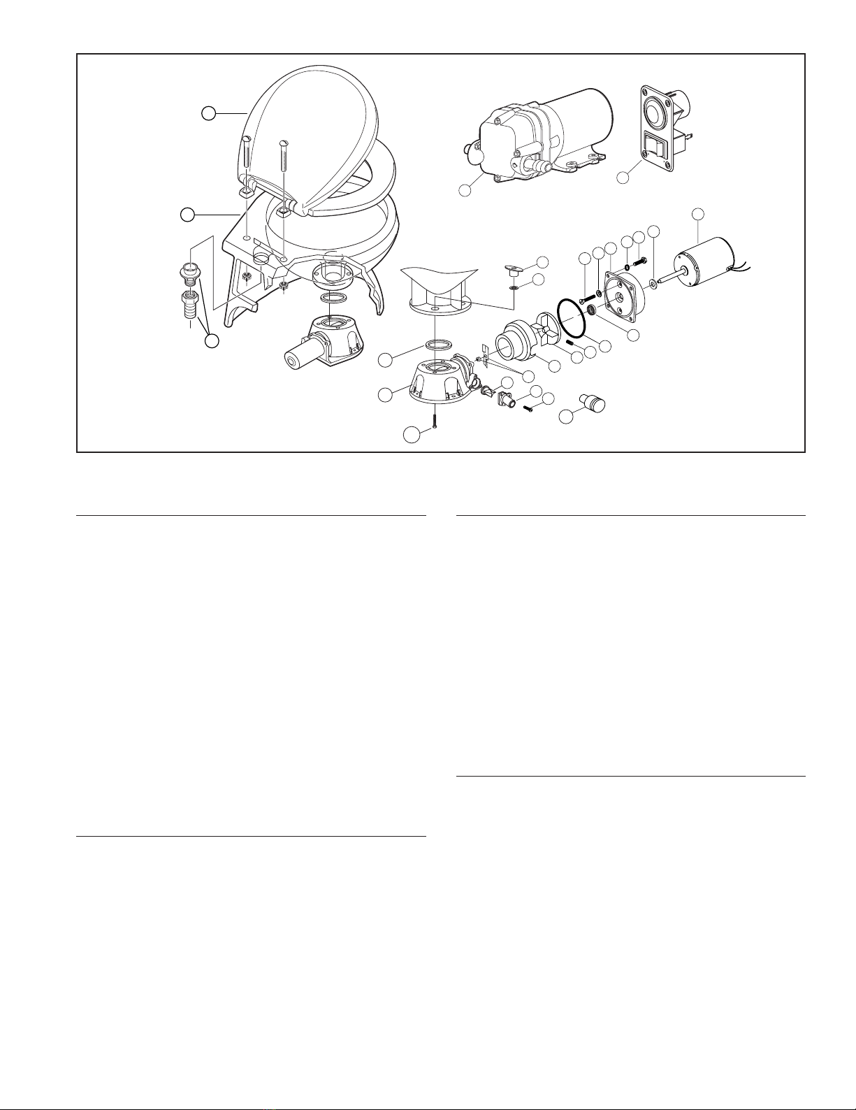
To replace the shaft seal, remove the two toilet hold-
down screw caps and remove the hold-down screw nuts.
Carefully lift the toilet up and away from the bulkhead at
it’s rear. Remove the pump assembly by removing the
four screws with lock washers that secure it to the plas-
tic toilet base. Carefully slide the pump assembly from
the base ensuring the macerator housing also slides out
of the base with the pump. The pump chopper will
engage the macerator housing and it may be necessary
to gently tap the chopper against the macerator housing
to free it from the base.
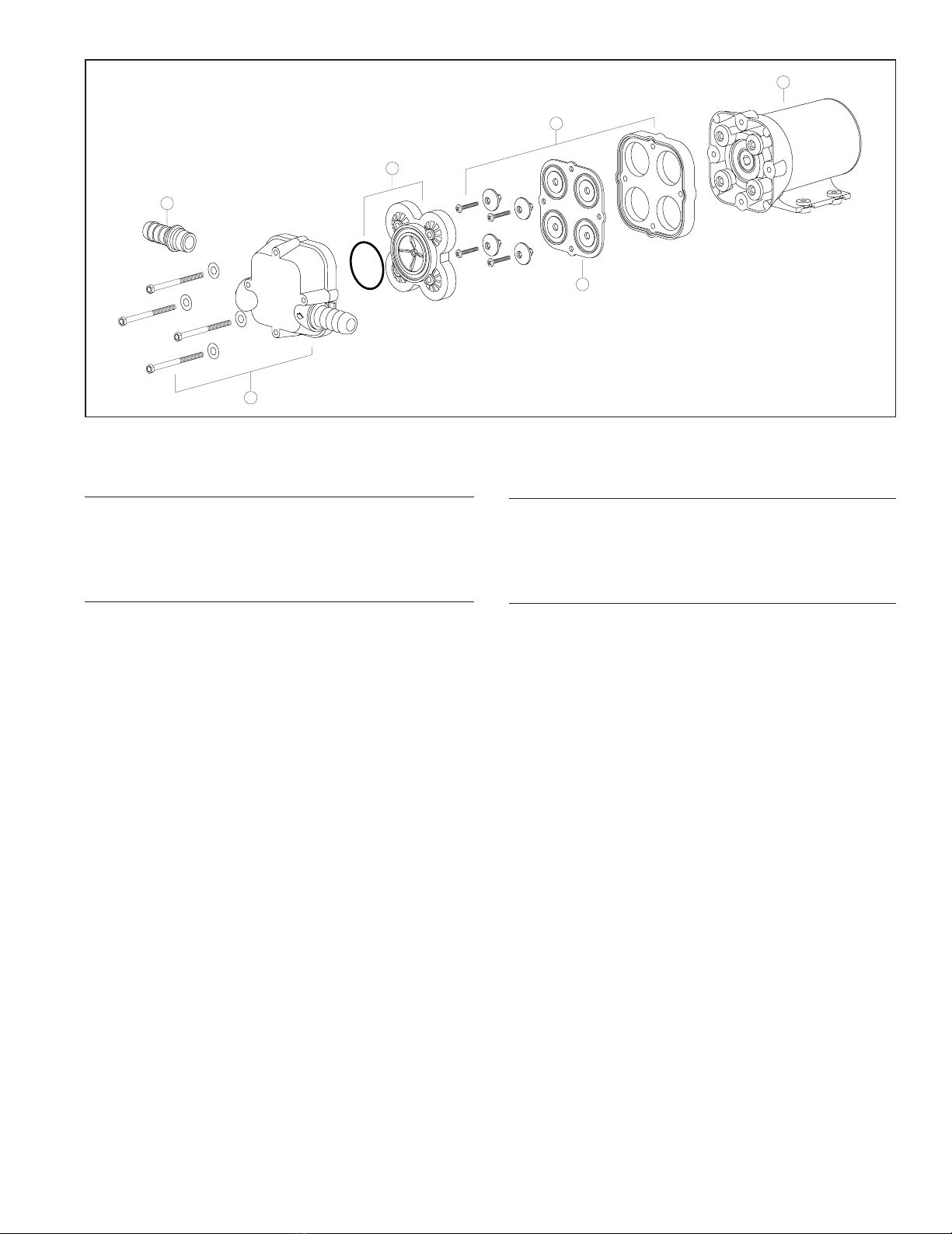
Prevent the motor shaft from turning by inserting a
screwdriver in the shaft slot at the rear of the motor and
remove the self locking nut. Remove the chopper and
macerator housing from the motor shaft. Remove the
O-ring from the O-ring groove around the outer diameter
of the seal housing. With an allen wrench, loosen the
centrifugal impeller set screw and slide the impeller off
the shaft. Remove the two screws that secure the seal
housing to the motor and slide the housing off the motor
shaft. Remove the two seal washers from under the
head of each of the two seal housing retainer screws.
With a pair of needle nose pliers, grasp the shaft seal
and pull it from the seal housing. Clean all parts and
inspect for damage.
Lubricate the OD of the new seal with a small amount of
water and press it into the seal bore with the seal’s lip fac-
ing the threaded end of the shaft. Do not use the stain-
less steel star retaining washer supplied with the seal.
Lubricate the ID of the seal and the motor shaft with a
small amount of water resistant grease. Ensure the
slinger is properly positioned on the motor shaft next to
the motor and slide the seal housing onto the motor shaft
until it is against the motor end bell. Position a new plas-
tic seal washer under the head of each of the flat head
seal housing retainer screws and secure the seal hous-
ing to the motor. Slide the centrifugal impeller on the
motor shaft positioning it about 1/32"(1 mm) from the
seal housing and secure it to the shaft with the set
screw. Rotate the impeller to ensure it does not rub on
the seal housing.
Slide the macerator housing over the motor shaft. Place
the chopper on the shaft with the tab on the flat of the
shaft. Install the self locking nut and tighten firmly while
holding the motor shaft at the rear of the motor. Position
a new O-ring in the seal housing O-ring groove (it may
be retained in the groove with a small amount of grease).
Slide the pump assembly into the toilet base ensuring
the macerator housing is properly positioned within the
base. The cut-out in the side of the macerator housing
must align with the discharge port in the base (the
macerator housing is keyed so it will only go in when
properly positioned). Ensuring the O-ring is still properly
positioned in the O-ring groove in the seal housing,
place the pump assembly against the base and secure it
in place with the four screws and lock washers.
Carefully lift the toilet and position over the two hold-
down screws using caution not to chip or break the china.
Secure the toilet down with the hold-down nuts and
washers ensuring the plastic washer is next to the china.
Do not overtighten hold-down nuts.
Flood hazard. If toilet is plumbed to an
overboard discharge, close the discharge
seacock prior to disassembling toilet.
Failure to do so can result in flooding which
can cause loss of property and life.
WARNING
!
4
43000-0665 10/11/02 5:56 PM Page 4

5
11
10
9
8
17
12
13 14 15
16
18 19 20 21 22
23
25
FLUSH
FILLDRAIN
4A
4B
1
2
3
24
5
6
7
4C
EXPLODED VIEW
PARTS LIST
Qty. Part
Key Description Req. Number
1 Seat & Cover 1 37078-1000
2 Bowl, Compact Size, White 1 37076-0010
Bowl, Standard Size, White 1 37076-1010
Bowl, Compact Size, Bone 1 37076-2010
Bowl, Standard Size, Bone 1 37076-3010
3 Bowl Spud and 3/4"barbed adaptor 1 18753-0609
4 Bowl Installation Hardware 1 18753-0604
4A Tee Nut** 4
4B Washer, Plastic** 4
4C Socket Head Screw** 4
5 Gasket* 1 37017-0000
6 Base Assembly** 1 37004-1000
7 1-1/2"Adaptor, Discharge Port 1 98023-0080
8 Joker Valve* ** 1 44106-1000
91"Discharge Port** 1 37077-1000
10 Screw** 3 96050-0568
11 Chopper Plate with Lock Nut, 1 37056-1000
12 Macerator Housing 1 37014-0000
13 Centrifugal Impeller 1 37006-0000
14 Set Screw 1 18753-0492
15 O-ring* 1 43990-0066
Qty. Part
Key Description Req. Number
16 Seal 1 1040-0000
17 Screw 2 91010-0144
18 Washer, Plastic* 2 35445-0000
19 Seal Housing 1 37043-1000
20 Lock Washer #10, Stainless Steel 4
21 Screw 4 91027-0011
22 Slinger 1 6342-0000
23 Motor - 12 Volt EMC 1 18753-0582
Motor - 24 Volt EMC 1 18753-0583
24 PAR-MAX 4 Rinse Water Pump
12 Volt EMC 1 30631-1092
24 Volt EMC 1 30631-1094
25 Switch Panel 1 37047-1000
Service Kit 1 90197-0000
Waste Pump Assembly
12 Volt EMC 1 37072-0092
24 Volt EMC 1 37072-0094
* Parts supplied with Service Kit.
** Parts included with base 37004-1000.
43000-0665 10/11/02 5:56 PM Page 5

PAR-MAX SERVICE INSTRUCTIONS
The PAR-MAX rinse water supply pump needs no peri-
odic maintenance for proper performance. The only time
service work should need to be performed on the pump
is if it should begin to leak water, suddenly delivers less
water than normal or should stop pumping altogether.
Should the pump begin to leak water, it will be necessary
to replace the diaphragm. If the pump delivers a reduced
rate of flow from normal or stops pumping altogether, it
will be necessary to either remove debris from the
pump’s flapper valves or replace the valve cage assem-
bly.
NOTICE: Before performing any service, turn off the
electrical power to the toilet and rinse water pump. Take
precaution to ensure it is not turned on until service is
complete. Close the inlet fitting seacock.
It is generally easiest to remove the pump from its
installed position so that the service can be performed
on a work bench. To do this, disconnect the electrical
wires from the motor wire leads. Push the port retainer
clips back toward the pump motor and pull the port fit-
tings from the port sockets. Unscrew the four pump
mounting fasteners and remove the pump to a location
where it can be disassembled without losing any of the
pump components.
Loosen the four 5/16"hex (slotted) machine screws in
the pump body and remove the body from the motor and
wobble plate housing (use care to not drop and lose the
port retainer clips and body retaining screws and wash-
ers). The valve cage will now be exposed which can be
easily lifted off the diaphragm. Inspect the four outer inlet
valves and central discharge valve to ensure they seat
smoothly against the valve cage. Lift the outer edges of
each valve to make certain there is no debris lodged
under any valve. If there is debris lodged under any of
the valves, it will cause a diminished flow rate or loss of
flow entirely. If the valves do not seat smoothly against
the valve cage, the valve cage assembly should be
replaced.
If the pump has been leaking, the diaphragm must be
replaced. Remove the four phillips head diaphragm
retainer screws and mushroom shaped diaphragm
retainer caps. Remove the diaphragm and diaphragm
housing from the motor and wobble plate housing.
Inspect the wobble plate bearing to make certain it is not
corroded and still rotates smoothly.
With the new diaphragm positioned in the diaphragm
housing (ensure the raised sealing beads face outward
away from the motor) hold it against the wobble plate
with the four retaining cap holes aligned with the wobble
plate sockets. Push each diaphragm retainer cap
through the diaphragm and into the socket of the wobble
plate. Secure each retaining cap to the wobble plate with
a 1"phillips head retainer screw. Place the motor on its
rear end bell and position the valve cage against the
diaphragm ensuring each cavities seal groove is seated
on its sealing bead molded into the diaphragm. Ensure
the O-ring seal that separates the pumps intake cham-
ber from the discharge chamber is properly seated in the
ID of the raised lip around the central discharge valve.
While holding the port retainer clips in their slide grooves
in the pump body, position the body on the diaphragm
and inside the wobble plate housing. Secure the pump
body to the wobble plate housing with the four 2-1/4"
machine screws and flat washers.
Reinstall the pump to its mounting surface with four fas-
teners through the rubber grommets. Ensure the sealing
O-ring is properly positioned on each port fitting and,
with the retaining clips slid back, push each port fitting
into its respective socket. Slide each port retainer clip
forward until it snaps securely into its seated position.
Reconnect the orange motor lead to the positive supply
wire and the black motor lead to the negative wire.
Ensure the inlet seacock is open before restoring power
to and operating the toilet.
6
43000-0665 10/11/02 5:56 PM Page 6

3
5
6
4
2
1
EXPLODED VIEW
PARTS LIST
Qty. Part
Key Description Req. Number
1 Port Kit (1 Pair) 1 30653-1004
2 Body Kit 1 30608-1001
3 Valve Cage / Valve Assy. 1 30613-1000
4 Diaphragm Kit 1 30617-1000
5 Diaphragm Housing & 1 30682-1000
Retainer Cap Kit
A. LIMITED WARRANTY: ITT warrants that at the time of ship-
ment, the products manufactured by ITT and sold hereunder shall
be in conformity with applicable written specifications and descrip-
tions referred to or set forth herein, free from defects in material
and workmanship, merchantable, and suitable for a particular pur-
pose, provided such is implied by State law under the circum-
stances of this sale.
B. WARRANTY ADJUSTMENT:
1. ITT agrees to repair or furnish a replacement for, but not to
remove or install, any product or component thereof which,
within one (1) year from date of purchase, shall upon test and
examination by ITT prove defective within the above warranty.
Receipt verifying purchase date is required to obtain adjust-
ment.
2. Buyer shall notify ITT of any defect within this warranty no later
than ninety (90) days after the defect is discovered.
3. No product will be accepted for return or replacement without
the prior written authorization of ITT. Upon such authorization,
and in accordance with instructions from ITT, the product will be
returned to ITT, shipping charges prepaid by Buyer. Products
returned to ITT will be addressed as follows:
ITT JABSCO
1485 Dale Way
Costa Mesa, California 92626-3998
Or to such alternate locations as may be designated on the
product, its container, or this sheet. Repair or replacement made
under this warranty will be shipped prepaid to Buyer.
C. EXCLUSIONS FROM WARRANTY AND LIMITATION OF
LIABILITY:
1. The foregoing warranty is limited solely as set forth herein and
applies only for the period designated above.
2. ITT SHALL NOT BE LIABLE FOR ANY LOSS, DAMAGE, SPE-
CIAL OR CONSEQUENTIAL DAMAGE OF ANY KIND,
WHETHER BASED UPON WARRANTY, CONTRACT, NEGLI-
GENCE, OR STRICT LIABILITY ARISING IN CONNECTION
WITH THE SALE, USE, OR REPAIR OF THE PRODUCT.
3. THE MAXIMUM LIABILITY OF ITT IN CONNECTION WITH
THIS WARRANTY SHALL NOT IN ANY CASE EXCEED THE
CONTRACT PRICE FOR THE PRODUCT CLAIMED TO BE
DEFECTIVE OR UNSUITABLE.
4. This warranty does not extend to any product manufactured by
ITT which has been subjected to misuse, neglect, accident,
improper installation, or use in violation of instructions furnished
by ITT.
5. This warranty does not extend to or apply to any unit which has
been repaired or altered at any place other than ITT's factory, or
by persons not expressly approved by ITT, nor to any unit the
serial number, model number, or identification of which has
been removed, defaced or changed.
6. Components manufactured by any supplier other than ITT shall
bear only that warranty made by the manufacturer of that product.
7. This warranty applies to products defined as “consumer prod-
ucts”by the Consumer Product Warranties Act as from time to
time amended.
D. CONSUMER RIGHTS: This warranty gives you specific legal
rights, and you may have other rights which vary from state to
state. Some states do not allow exclusion or limitation of damages.
STANDARD WARRANTY: If the products manufactured and sold
hereunder are not Consumer Products, the warranty extended to
Buyer shall be as set forth in subparagraphs (A), (B), and (C),
EXCEPT THAT ALL EXPRESS OR IMPLIED WARRANTIES OR
MERCHANTABILITY OR SUITABILITY FOR ANY PARTICULAR
PURPOSE ARE EXCLUDED.
Qty. Part
Key Description Req. Number
6 Motor Kit 12 Vdc EMC 1 18753-0577
Motor Kit 24 Vdc EMC 1 18753-0578
Motor / Pump Assy.12 Vdc EMC 1 30631-1092
Motor / Pump Assy. 24 Vdc EMC 1 30631-1094
ONE YEAR LIMITED WARRANTY
7
43000-0665 10/11/02 5:56 PM Page 7

AB
C
DE
1 Dia
(25.4)
8-7/8
(225) 10
(254)
16-3/4
(425)
8-1/2
(216)
13-1/2
(343)
U.S.A.
Jabsco
20 Icon
Foothill Ranch, CA 92610-3000
Tel: (949) 609.5106
Fax: (949) 859.1254
UNITED KINGDOM
Jabsco
Bingley Road, Hoddesdon
Hertfordshire EN11 OBU
Tel: +44 (0) 1992 450145
Fax: +44 (0) 1992 467132
CANADA
Fluid Products Canada
55 Royal Road
Guelph, Ontario N1H 1T1
Tel: (519) 821.1900
Fax: (519) 821.2569
JAPAN
NHK Jabsco Company Ltd.
3-21-10, Shin-Yokohama
Kohoku-Ku, Yokohama, 222
Tel: 045.475.8906
Fax: 045.475.8908
GERMANY
Jabsco GmbH
Oststrasse 28
22840 Norderstedt
Tel: +49-40-53 53 73 -0
Fax: +49-40-53 53 73 -11
© Copyright 2002, ITT Industries Printed in U.S.A. All Rights Reserved Form: 43000-0665 Rev. 10/2002
THE PRODUCTS DESCRIBED HEREIN ARE
SUBJECT TO THE JABSCO ONE YEAR LIMITED
WARRANTY, WHICH IS AVAILABLE FOR YOUR
INSPECTION UPON REQUEST.
2-5/16
(59) 1-3/4
(44)
4-1/16
(103)
3-7/8
(99)
3-1/2
(89)
1-3/4
(44)
4-1/8
(105)
6
(152) 8
(203)
3-3/4
(95)
5/8
(16)
2
(51)
BLACK
(NEGATIVE) LEAD
ORANGE
(POSITIVE) LEAD
DIMENSIONAL DRAWINGS Inches (Millimeters)
Compact Size Bowl Standard Size Bowl
A 19-3/16 (487) 19-3/16 (487)
B 15-1/2 (394) 15-1/2 (394)
C 14-1/4 (362) 17-1/4 (438)
D 8-7/8 (225) 8-7/8 (225)
E 11-13/16 (300) 11-13/16 (300)
43000-0665 10/11/02 5:56 PM Page 8
This manual suits for next models
8
Table of contents
Other ITT Industries Toilet manuals
Popular Toilet manuals by other brands

Dometic
Dometic VacuFlush 4848 installation guide

SmartBidet
SmartBidet SB-2600 Quick installation guide

Dometic
Dometic SANIPOTTIE 960 Series instruction manual

Roca
Roca MULTICLEAN PREMIUM A80400800 manual

Woodbridge
Woodbridge B0940 installation instructions

LIXIL
LIXIL American Standard 760408-100.0070A installation instructions