Clevo 8500V Series User manual


Part 1: Introduction and Specifications.................... 1-1
Specifications ..........................................................................1-2
Part 2: Chipsets and Mainboard..................................2-1
Mainboard................................................................................2-2
Microprocessor.....................................................................2-2
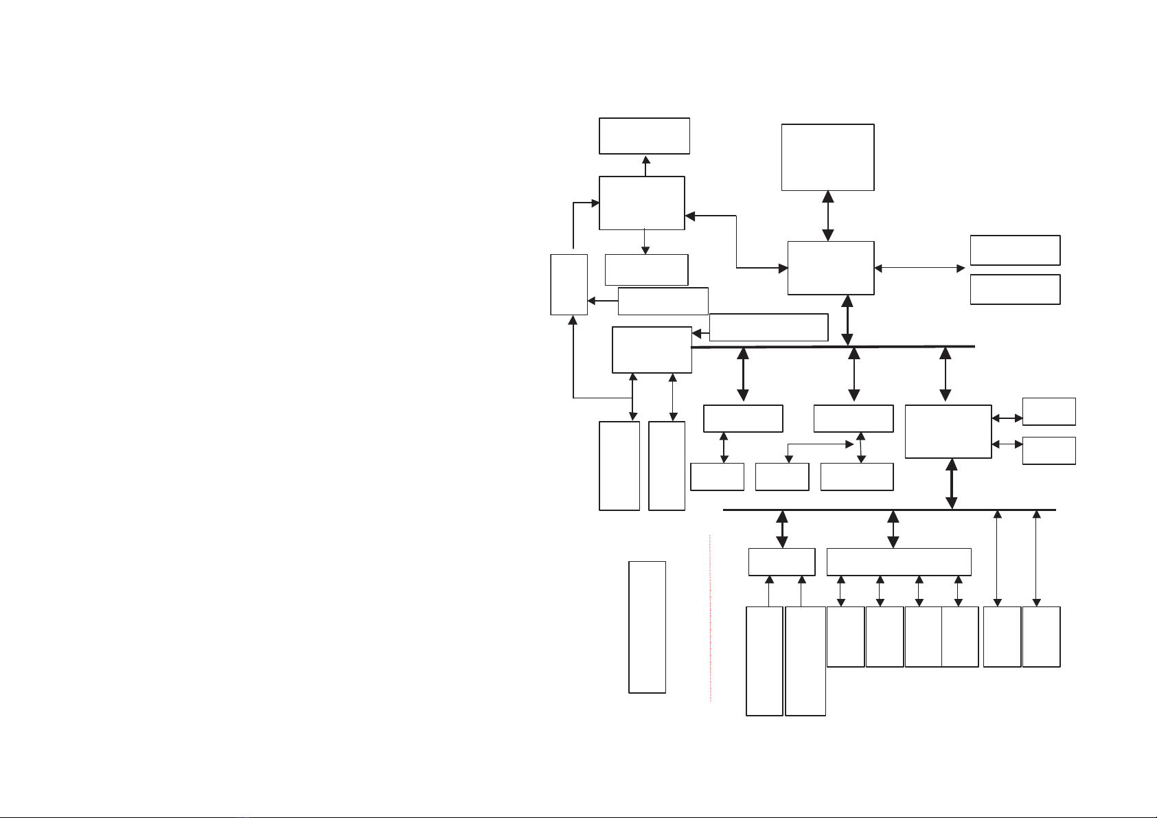
82C694X Host Bridge System Controller..........................2-3
Southbridge Chip - VIA 82C686A.......................................2-3
VGA Controller – ATI 3D RAGE Mobility-128 .................2-4
PC Card (Card Bus) Interface Controller - TI-4450 .........2-4
ZV Port Custom Interface ...................................................2-5
Super I/O Floppy Disk Controller – FDC37N869.............2-5
Serial Port.............................................................................2-6
High Performance PCI Audio Chip - ES1988 ....................2-6
Audio CODEC ES1921.........................................................2-6
Video-In Decoder 7114A......................................................2-6
Keyboard Controller - M38867M8......................................2-7
IEEE 1394 – TI PHY TSB41LV02.......................................2-7
LAN 100/10 Mbps – RTL8139C ...........................................2-7
D/D Board ................................................................................2-9
Top View ...............................................................................2-9
Bottom View .........................................................................2-9
Mainboard Top View ............................................................2-10
Mainboard Bottom View ......................................................2-11
Connector and pin information ...........................................2-12
HDD.....................................................................................2-12
CD-ROM..............................................................................2-13
FDD .....................................................................................2-13
RS-232 Serial Interface.....................................................2-14
Parallel Interface ...............................................................2-14
External Keyboard/PS2 Interface ....................................2-14
External Monitor Interface...............................................2-15
External S-video out Interface ........................................2-15
Touchpad Interface ...........................................................2-15
External 1394 (IEEE) Interface........................................2-15
External USB Interface-port A.........................................2-15
External USB Interface-port B.........................................2-15
PCMCIA Cardbus Interface Socket A..............................2-16
PCMCIA Cardbus Interface Socket B..............................2-17
Part 3: Installing a processor....................................... 3-1
A: Remove the heat sink ........................................................3-2
B: Remove the existing processor .........................................3-2
C: Install a new processor......................................................3-4
D: Install the heat sink...........................................................3-6
Part 4: BIOS ......................................................................4-1
Updating the Flash ROM BIOS.............................................4-2
A: Download the BIOS update from the web site............4-2
B: Create a bootable Floppy Disk......................................4-2
C: Copy your BIOS files on to the bootable Floppy Disk.4-3
D: Reboot your computer from the FDD ..........................4-3
E: Reboot your computer from the HDD ..........................4-3
Phoenix BIOS Post Error Messages .....................................4-4
Fatal Errors ..........................................................................4-4
Nonfatal errors.....................................................................4-5
Flash ROM Error codes.......................................................4-7
Notes: .......................................................................................4-8
Part 5: Diagrams and part numbers ........................... 5-1
CD-ROM Assembly .................................................................5-2
FDD Assembly.........................................................................5-3
HDD Assembly ........................................................................5-4
LG Display Panel ..................................................................5-5
(Panasonic, Sanyo, Hyundai, Hitachi) Display Panel..........5-6
Bottom View............................................................................5-7
Top View ..................................................................................5-8
Part 6: Schematics ......................................................... 6-1
Contents

1 – 1
Part 1: Introduction and Specifications
The model 8500V notebook computer supports up to an 800MHz Intel Pentium!!! processor. The 8500V features a 15.0” TFT LCD
panel and one bay for a removable FDD module, which is interchangeable with a Zip 250MB Drive or secondary IDE HDD. This prod-
uct also features one bay for a removable CD-ROM, which is interchangeable with a DVD-ROM or CD-RW Drive.

1 –2
Service Manual
Specifications
Structure
- Full PC 99 Compliant
- ACPI 1.0B Compliant
Security
- Kensington® Lock
Processor
- Intel Pentium III 500/533/550/600/650/667/700/733/750/800/850/866/933 MHz ( FC-PGA 370 Package)
Memory
- Provides 64 bit data bus system memory
- Expandable memory up to 512 MB, depend on 32/64/128/256 MB SODIMM Module
- Two PC-100 or PC-133 compliant 144-pin SODIMM sockets, support Sync DRAM SODIMM (3.3V)
BIOS
- One 256KB Flash ROM
- Phoenix BIOS with Smart Battery, Plug and Play ( 1.0a ), ACPI 1.0B
LCD
- 15.0” XGA(1024 x 768) /SXGA+(1400 x 1050) TFT LCD panel (18bit)
Display
- AGP 2X
- 128-bit Hardware 2D Accelerator Graphics Engine
- Hardware 3D Accelerator Graphics Engine

1 –3
Part 1: Introduction and Specifications
- Motion Compensation and IDCT for DVD playback Acceleration
- High quality TV-out with MacroVision® V7.01 anti-copy technology
- 8 or 16MB Video memory
- CRT resolution up to 1600x1200 x16M non-interlaced
- TV resolution 1024x768 x 32bpp
- DuoView display capability under Windows 98
- Supports external Video Input
Storage
- Removable 3.5" 3-mode FDD, interchangeable with a 15 mm (h) Zip 250MB Drive (IO MEGA), or 2.5” 12.7mm(h) / 12.5mm(h) second-
ary IDE HDD
- Removable 24X speed CD-ROM, interchangeable with DVD-ROM or CD-RW
- Removable 2.5" 9.5mm/ 12.7 mm/ 17.0 mm (h) HDD
- Support DMA mode 2/ PIO mode 4/ ATA-33 /ATA-66 IDE HDD
Audio
- AC 97 Compliant
- Compatible with Sound Blaster Pro™
- HRTF 3D Positional Audio, DirectSound and DirectSound 3D Acceleration
- AC-3 Virtualization
- S/PDIF output for DVD content
- IIS interface for external ZV port or MPEG audio
- Built in microphone
- 2 built in 2 watt speakers

1 –4
Service Manual
Keyboard
- 101/102 Key Win 95 keyboard includes numeric keypad
PCMCIA
- Two (PCI) PCMCIA 3.3V/5V sockets, type II x2 or type III x1
- Supports Zoomed Video Port / CardBus (PC Card95)
Interface
- Built in Touchpad (PS/2)
- IEEE 1394 port
- Dual USB port
- One serial port (COM1)
- One parallel port (LPT1) , support ECP / EPP 1.7and 1.9
- Fast Infrared (FIR) file transfer, IrDA 1.1 or ASKIR (SHARP standard)
- One External CRT monitor port.
- One S-Video jack for TV output
- One RCA jack for Video input
- One PS/2 port for External keyboard or Mouse (PS/2 type)
- One jack for line-in /speaker out
- One speaker-out jack
- One jack for microphone / S/PDIF output
- One RJ-11 jack for 56K MDC Modem
- One RJ-45 jack for 100M/10M LAN
- One (120 pins) connector for Port Replicator
- DC-in jack

1 –5
Part 1: Introduction and Specifications
Communication
- Wireless Infrared transfer IrDA 1.1, 1cm~1M operating distance, 4Mbps FIR
- 56K MDC Modem with V.90 compliant
- 100M/10M LAN
PMU
- Supports ACPI v1.0B
- Supports APM v1.2 Soft Off
- Device Power Management
- CPU over temperature protection
- Supports suspend to disk
- Battery low suspend
- Resume from alarm time/ modem ring ( COM port Only)
- Smart Fan Control
Power
- Full Range 65 watts AC adapter – AC in 100~240V,47~63Hz.
- One Smart Lithium-Ion Battery
Indicator
- LED with AC-IN / HDD Accessing / Battery Charge / Suspend indicator
Certificate
- FCC Class B , CE, VCCI, CTICK, UL, CUL, TUV, CB
- Windows Logo, Macrovision, CTR21, Part 68
- Environmental

1 –6
Service Manual
Spec.
- Temperature Operating: 50 C~ 350C; Non-Operating : -200C ~ 600C
- Relative Humidity Operating : 20% ~ 80%; Non-operation: 10% ~ 90%
Physical
- 358(w) x 280(d) x 50(h) mm3
Weight
- 4.2 kg with Lithium-Ion battery
Optional
- 3002 Lithium-Ion smart battery pack
- 8006A Port Replicator
- 8007 IO Mega 100 MB ZIP Drive
- 800D DVD-ROM Driver Module 12.7mm (h)
- 800E CD-RW Driver Module 12.7mm (h)
- 800F Software DVD Player
- 800J 56K Modem Module (MDC) with V.90 compliant
- 800I IO Mega 250MB Zip Drive
- 800H 9000mAh Lithium-Ion Battery Pack

2 – 1
Part 2: Chipsets and Mainboard
ATI
M3
AGP BUS
TI
4450
PCI BUS 3.3V
USB
IDE
FDC37N869
M38867
ISA BUS
EXT K/B MOUSE
COM1
LPT1
FIR
FDD
Intel
Socket 370
FC-PGA
VIA
82C694X
SODIMM1
GTL+ HOST BUS
VIA
82686A
ESS1988
SOCKET B
MOUSE
SOCKET A
MOUSE
7114A
ZV PORT
PHY TSB41LV02
BIOS
RTC
PCI I/F
SODIMM0
ESS1921
PORT REPLICATOR
MM BUS
INT K/B MOUSE
TV OUT
VIDEO IN
LVD
S
Interface
MDC
RTL8139C
RJ-45

2 –2
Service Manual
Mainboard
The mainboard is designed with Intel 370 Socket processor base and includes the following CHIPSET functions:
- 82C694X North bridge chipset solution from VIA
- 82C686A South bridge chipset solution from VIA
- ATI 3D RAGE Mobility-128 Multimedia Flat Panel Controller
- TI 4450 PC CARD Controller
- FDC37N869 super I/O Floppy Disk Controller
- ES1988 PCI Audio Chip and ES1921 AC97’ CODEC
- 7114A Video-in decoder
- M38867(Version 1.44) Keyboard Controller
- TSB41LV02 PHY for IEEE1394
- Realtek RTL8139c Controller for 10/100 Mbps LAN
Microprocessor
Intel Pentium!!! processor product line. Features include:
- P6 core (FC-PGA package)
- Separated 16K instruction and 16K data level one caches
- Integrated 256K second level cache
- 4GB of system memory which can be cached
- High performance Floating Point Unit
- Enhanced 64 bit data bus
- Dynamic Execution micro-architecture
- MMX media technology instruction
- Power management features
- Low power GTL+ Host bus specification

2 –3
Part 2: Chipsets and Mainboard
82C694X Host Bridge System Controller
VIA’s 82C694X Host Bridge system controller is a highly integrated device that combines the processor bus controller, the DRAM
controller, and the PCI bus controller into one component. The 82C694X Host Bridge has multiple power management features:
- Host Interface
- Memory Interface
- PCI Interface
- AGP Interface
Southbridge Chip - VIA 82C686A
Contains the following features:
- Supported Kits for both PentiumII and Pentium!!! microprocessors
- Multifunction PCI to ISA Bridge
+ Supports PCI at 33 MHz
+ Supports PCI Rev 2.1 Specification
+ Supports Full ISA or Extended I/O BUS
- Ultra-low power for Mobile Environment Support
- Full Support for ACPI (Advanced Configuration and Power Interface) Revision 1.2
- Integrated IDE Controller Support Ultra DMA/33/66
+ Supports two 82C37 Enhanced DMA Controller
+ Supports two 82C59 Interrupt Controller
+ Supports 82C54 Timer Based
+ Supports UHCI V1.1 USB Ports
+ Supports SMBus

2 –4
Service Manual
VGA Controller –
ATI 3D RAGE Mobility-128
The ATI 3D RAGE MOBILITY-128 Multimedia Flat Panel Controller is a DRAM based fully integrated LCD, CRT & TV 64 bits con-
troller for AGP systems. It contains the following functions:
- Supports displays for 8 MB or 16 MB
- 64 bit high performance 2D/3D Graphic Engine
- Supports bus master AGP and SGRAM memory
- Supports 24 bit TFT panels up to 1280x1024 resolution
- Supports non-interlaced 1600x1200x64k, 1280x1024x64k, 1024x768x16M, 800x600x16M and 640x480x16M color on CRT
- Simultaneous display in 24 bit color on flat panel and CRT
- Internal buffer provides flicker reduction
- ATI 3D RAGE MOBILITY-128 DAC can directly interface with a standard off-the-shelf NTSC/PAL encoder. Composite synchroni-
zation signals support for standard home TV connection up to 1280x1024x16M and 16:9 Wide mode
- Graphic functions optimized by a 64 bit internal data bus and VGA, SVGA and XGA flat panel
- Provide flexible and extensive power management capabilities and support four states of VESA Display Power Management Sig-
naling Standard
- IDCT for DVD playback acceleration
- Fully compliant ZV-port interface with device driver supports for VPM
- Motion compensation
PC Card (Card Bus) Interface Controller - TI-4450
TI Card Bus Interface Controller 4450 implements the PCMCIA 2.0/JEIDA 4.1 standard. It contains the following functions:
- Supports 2 PCMCIA 2.1& JEIDA 4.2 R2 cards or 2 CardBus cards
- Yenta Registers-compatible
- Supports Zoom Video Mode
- PCMCIA dual-socket interface
- Supports Ultra Zoomed Video Ports

2 –5
Part 2: Chipsets and Mainboard
- Bus Master Transfer capability
- Supports both 5V and 3.3V PC cards
- Supports PCMCIA_ATA Specification
- Supports Advanced Submicron Low Power CMOS Technology
- ACPI 1.0 Compliant
- 256 pin Micro-Star BGA package
- OHCI Link Function is IEEE 1394-1995 Compliant and compatible with Proposal 1394
ZV Port Custom Interface
The ZV (Zoomed Video) Port is a single source, point-to-point unidirectional video bus between a PC Card socket and a VGA control-
ler. The ZV Port complies with CCIR601 timing to allow NTSC decoders to deliver real-time digital video straight into the VGA frame
buffer from a PC Card. The ZV Port also allows an industry standard mechanism for transferring digital audio PCM data to a low cost
DAC for conversion to an analog signal.
Super I/O Floppy Disk Controller –FDC37N869
The SMC FDC37N869 super I/O is optimized for mainboard applications. It provides:
- Intelligent Auto Power Management
- 16 Bit Address Qualification
- 1.44MB Super I/O Floppy Disk Controller
+ Support Vertical Recording Format
+ 16 Byte Data FIFO
+ Enhanced Digital Data Separator (Data rate up to 1Mb/s)
- Multi-Mode Parallel Port with ChiProtect Circuitry
+ Standard Mode
IBM PC/AT and PS/2 compatible bidirectional parallel port
+ Enhanced Mode
Enhanced Parallel Port (EPP) Compatible

2 –6
Service Manual
+ High Speed Mode
Microsoft and Hewlett Packard Extended Capabilities Port (ECP) Compatible
Serial Port
- Two high speed NS16C550 compatible UARTs with Send/Receive 16 Byte FIFOs
- Programmable Baud Rate Generator
- Modem Control Circuitry
- Infrared-IrDA, HPSIR, ASKIR, Fast IR(4Mbps IrDA), Consumer IR Support
High Performance PCI Audio Chip - ES1988
- 500-MIPS-equivalent, dual-engine PCI audio accelerator
- HRTF 3-D positional audio acceleration
- 64 Channel wavetable synthesis
- Advanced platform for interactive 3-D gaming, DVD movie playback and internet communications
- Full plug and play
- Multi-Stream DirectSound and DirectSound3D acceleration
- Full DOS Game compatibility
- I2S Zoomed Video interface
Audio CODEC ES1921
- Single, high-performance, mixed-signal, 16 bit stereo VLSI chip
- Meet Audio Codec ‘97 analog performance specification
- Full-duplex operation for simultaneous record and playback
Video-In Decoder
7114A
The SAA7114 is a video capture device located at the image port of the VGA controller. It has the following features:
- Automatic detection of 50/60Hz field frequency and automatic switching between PAL and NTSC standards

2 –7
Part 2: Chipsets and Mainboard
- Luminance and chrominance signal processing for PAL BGDHIN, Combination-PAL N, PALM, NTSC M, NTSC-Japan, NTSC 4.43
and SECAM
- Two-wire, Inter-Integrated Circuit(I2C)
- User programmable sharpness control
Keyboard Controller - M38867M8
- Memory size: 1024 bytes (RAM)
- Timers: 8 bit prescaler X 4 + 8 bit timer X 3
- Comparator: 4 bit X 8 channels
- Bus interface: 2 bytes
- Key on wake-up: 8 channels
- Interrupts: 8 external, 7 internal and 1 software
- A-D converter: 8 channels
- D-A converter: 2 channels
- PWM: 2 channels
- System bus interface: 8042 type
IEEE 1394 –TI PHY TSB41LV02
- 400Mb/S max data rate
- Available with one or three ports
- Fully compliant with OpenHCI requirements
- Advanced Power Management
- Supports IEEE 1394-1995 Isolation Barrier Feature at LINK-PHY interface
LAN 100/10 Mbps –RTL8139C
- Supports Wake-On-Lan and ACPI features
- Single-chip fast Ethernet controller

2 –8
Service Manual
- Fully compliant with IEEE 802.3u 100Base-T SPEC and IEEE802.3x full duplex flow control
- Supports Analog Auto-Power-Down

2 –9
Part 2: Chipsets and Mainboard
D/D Board
Bottom View
Top View
1) D/D Board Connectors
1
1

2 –10
Service Manual
Mainboard Top View
4
6
7
7
8
9
5
3
2
1
1) LCD Connector
2) CMOS Battery
3) Southbridge Chip- VIA 82C686A
4) Video Chip - ATI 3D RAGE Mobility-128
5) MDC Card
6) Switch Connector
7) RAM Socket
8) Keyboard Connector
9) PCMCIA Connector

2 –11
Part 2: Chipsets and Mainboard
Mainboard Bottom View
1) CPU Socket
2) D/D board connectors
3) FDD connector
4) CD-ROM connector
5) PCMCIA chipset
6) HDD connector
4
6
5
3
2
1
2

2 –12
Service Manual
niP noitpircseD niP noitpircseD niP noitpircseD niP noitpircseD
1DNG61YDROIP1301PDD64#P3SC
2DNG71#KCADP2311PDD74DNG
3#TSRDH8141QRI3321PDD84CCV_DDH
47PDD911ADP4331PDD94CN
56PDD020ADP5341PDD05CN
65PDD12#P1SC6351PDD
74PDD22#DEL_DHP73CN
83PDD32CCV_DDH83DNG
92PDD42DNG93DNG
011PDD52CN04DNG
110PDD62DNG14LESC
21DNG72DNG24DNG
31QERDP82DNG34CN
41#WOIDP928PDD44CN
51#ROIDP039PDD542ADP
HDD
Connector and pin information
Table of contents
Other Clevo Laptop manuals