Introduction
Specifications 1 - 3
1.Introduction
Audio
High Definition Audio Compliant Interface
S/PDIF Digital Output
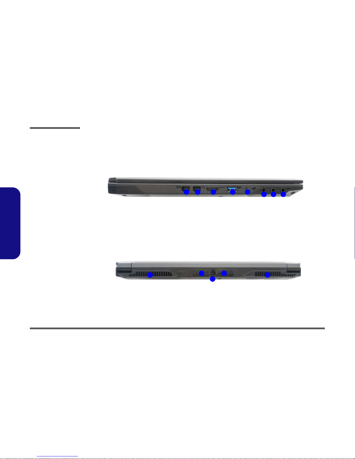
Two Speakers
Sound Blaster Audio
ANSP™3D sound technology on headphone output
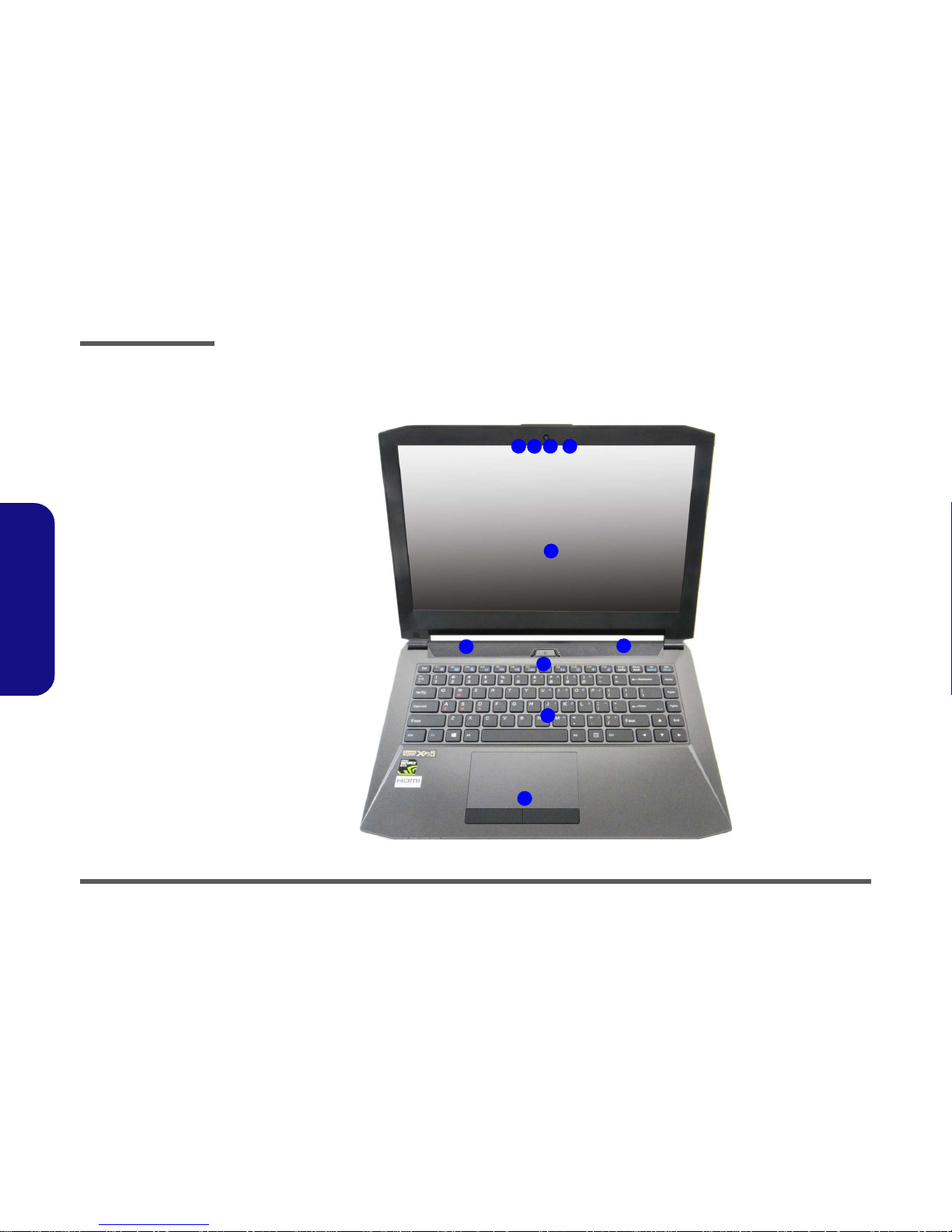
Built-In Array Microphone
Note: External 5.1CH Audio Output Supported by Headphone,
Microphone and S/PDIF Out Jacks
Security
Security (Kensington® Type) Lock Slot
BIOS Password
(Factory Option) TPM 2.0
Intel PTT for Systems Without TPM Hardware
Keyboard
Illuminated White-LED “WinKey” Keyboard (with embed-
ded numeric keypad)
Pointing Device
Built-in Touchpad
Card Reader
Embedded Multi-In-1 Push-Push Card Reader
MMC (MultiMedia Card) / RS MMC
SD (Secure Digital) / Mini SD / SDHC/ SDXC
M.2 Slots
Slot 1 for Combo WLAN and Bluetooth Module
Slot 2 for SATA or PCIe Gen3 x4 SSD
(Factory Option) Slot 3 for 3G/4G Module
Interface
One HDMI-Out Port
Two Mini DisplayPorts 1.2*
One S/PDIF Out Jack
One Headphone/Speaker-Out Jack
One Microphone-In Jack
One RJ-45 LAN
Jack
One DC-In Jack
Virtual Reality ready (via Mini DisplayPort 1 )
Three USB 3.0 (USB 3.1 Gen 1) Ports (Including one AC/DC
Powered USB port)
One USB 3.1 (Gen 2 - Type C) Port
Communication
Built-In Gigabit Ethernet LAN
2.0M FHD PC Camera Module
(Factory Option) M.2 3G/4G Module
WLAN/ Bluetooth M.2 Modules:
(Factory Option) Intel® Wireless-AC 8260 Wireless LAN
(802.11ac) + Bluetooth 4.1
(Factory Option) Intel® Wireless-N 7265 Wireless LAN
(802.11b/g/n) + Bluetooth 4.0
(Factory Option) Intel® Wireless-AC 3165 Wireless LAN
(802.11ac) + Bluetooth 4.0
(Factory Option) Qualcomm® Atheros Killer™ Wireless-AC
1535 Wireless LAN (802.11ac) + Bluetooth 4.1
(Factory Option) Third-Party Wireless LAN 802.11b/g/n +
Bluetooth 4.0
Environmental Spec
Temperature
Operating: 5°C - 35°C
Non-Operating: -20°C - 60°C
Relative Humidity
Operating: 20% - 80%
Non-Operating: 10% - 90%
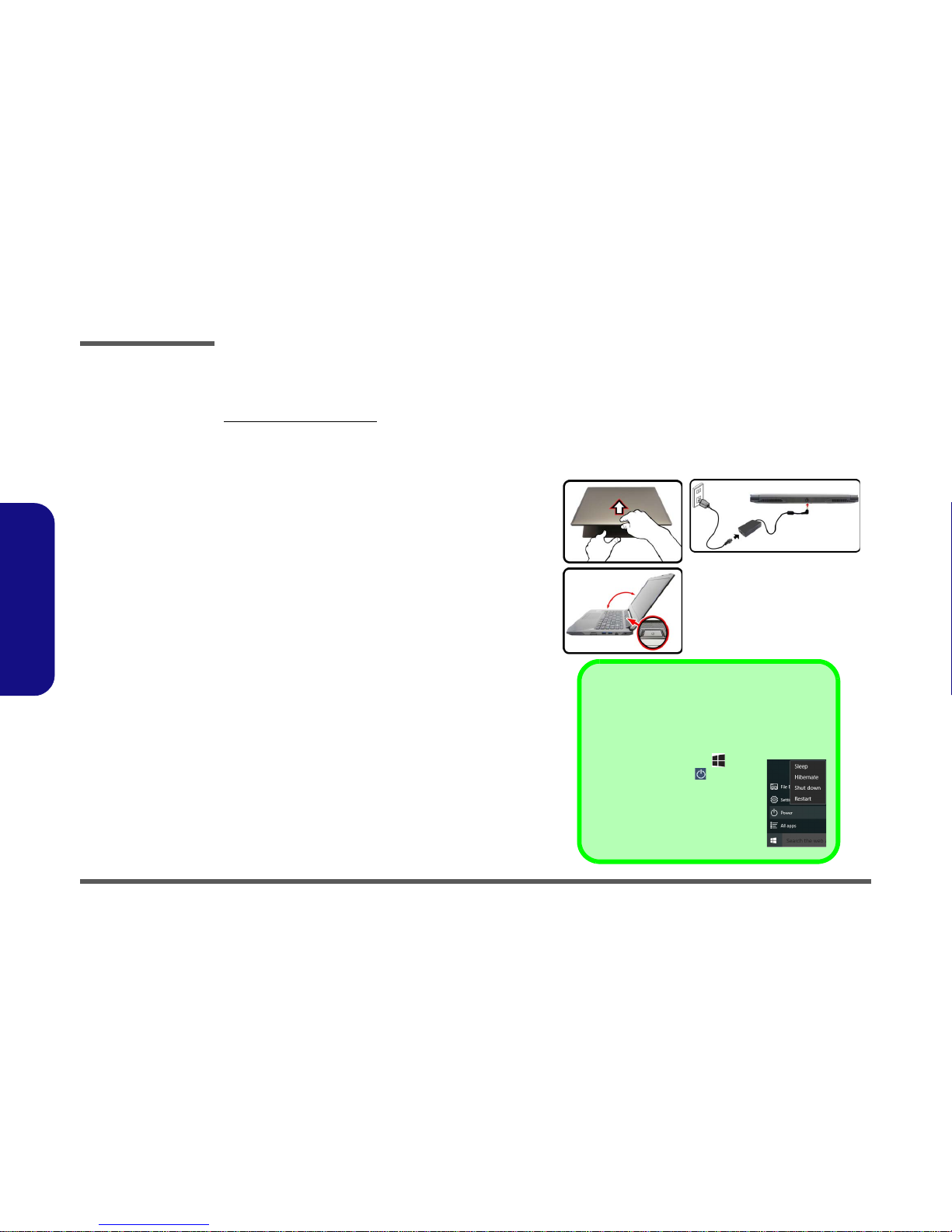
Power
Embedded 3-Cell Polymer Battery Pack, 45WH
Full Range AC/DC Adapter
AC Input: 100 - 240V, 50 - 60Hz
DC Output: 19.5V, 7.7A (150W)
Dimensions & Weight
349mm (w) * 247mm (d) * 25.4mm (h)
2.0kg (Barebone with 45WH Battery)