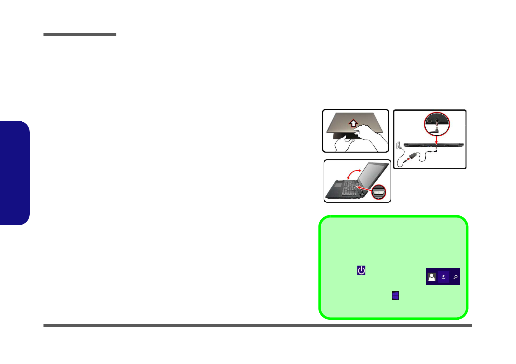
Clevo N150RF User manual

N150RF / N151RF

Preface
II
Preface
Notice
The company reserves the right to revise this publication or to change its contents without notice. Information contained
herein is for reference only and does not constitute a commitment on the part of the manufacturer or any subsequent ven-
dor. They assume no responsibility or liability for any errors or inaccuracies that may appear in this publication nor are
they in anyway responsible for any loss or damage resulting from the use (or misuse) of this publication.
This publication and any accompanying software may not, in whole or in part, be reproduced, translated, transmitted or
reduced to any machine readable form without prior consent from the vendor, manufacturer or creators of this publica-
tion, except for copies kept by the user for backup purposes.
Brand and product names mentioned in this publication may or may not be copyrights and/or registered trademarks of
their respective companies. They are mentioned for identification purposes only and are not intended as an endorsement
of that product or its manufacturer.
Version 1.0
December 2015
Trademarks
Intel and Intel Core are trademarks of Intel Corporation.
Windows®is a registered trademark of Microsoft Corporation.
Other brand and product names are trademarks and /or registered trademarks of their respective companies.

Preface
III
Preface
About this Manual
This manual is intended for service personnel who have completed sufficient training to undertake the maintenance and
inspection of personal computers.
It is organized to allow you to look up basic information for servicing and/or upgrading components of the N150RF /
N151RF series notebook PC.
The following information is included:
Chapter 1, Introduction, provides general information about the location of system elements and their specifications.
Chapter 2, Disassembly, provides step-by-step instructions for disassembling parts and subsystems and how to upgrade
elements of the system.
Appendix A, Part Lists
Appendix B, Schematic Diagrams
Appendix C, Updating the FLASH ROM BIOS

Preface
IV
Preface
IMPORTANT SAFETY INSTRUCTIONS
Follow basic safety precautions, including those listed below, to reduce the risk of fire, electric shock and injury to per-
sons when using any electrical equipment:
1. Do not use this product near water, for example near a bath tub, wash bowl, kitchen sink or laundry tub, in a wet
basement or near a swimming pool.
2. Avoid using a telephone (other than a cordless type) during an electrical storm. There may be a remote risk of elec-
trical shock from lightning.
3. Do not use the telephone to report a gas leak in the vicinity of the leak.
4. Use only the power cord and batteries indicated in this manual. Do not dispose of batteries in a fire. They may
explode. Check with local codes for possible special disposal instructions.
5. This product is intended to be supplied by a Listed Power Unit as follows:
• AC Input of 100 - 240V, 50 - 60Hz, DC Output of 19.5V, 6.15A (120 Watts) minimum AC/DC Adapter.
FCC Statement
This device complies with Part 15 of the FCC Rules. Operation is subject to the following two conditions:
This device may not cause harmful interference.
This device must accept any interference received, including interference that may cause undesired operation.

Preface
V
Preface
Instructions for Care and Operation
The notebook computer is quite rugged, but it can be damaged. To prevent this, follow these suggestions:
1. Don’t drop it, or expose it to shock. If the computer falls, the case and the components could be damaged.
2. Keep it dry, and don’t overheat it. Keep the computer and power supply away from any kind of heating element. This
is an electrical appliance. If water or any other liquid gets into it, the computer could be badly damaged.
3. Follow the proper working procedures for the computer. Shut the computer down properly and don’t forget to save
your work. Remember to periodically save your data as data may be lost if the battery is depleted.
Do not expose the computer
to any shock or vibration.
Do not place it on an unstable
surface.
Do not place anything heavy
on the computer.
Do not expose it to excessive
heat or direct sunlight.
Do not leave it in a place
where foreign matter or mois-
ture may affect the system.
Don’t use or store the com-
puter in a humid environment.
Do not place the computer on
any surface which will block
the vents.
Do not turn off the power
until you properly shut down
all programs.
Do not turn off any peripheral
devices when the computer is
on.
Do not disassemble the com-
puter by yourself.
Perform routine maintenance
on your computer.

Preface
VI
Preface
4. Avoid interference. Keep the computer away from high capacity transformers, electric motors, and other strong mag-
netic fields. These can hinder proper performance and damage your data.
5. Take care when using peripheral devices.
Power Safety
The computer has specific power requirements:
• Only use a power adapter approved for use with this computer.
• Your AC adapter may be designed for international travel but it still requires a steady, uninterrupted power supply. If you are
unsure of your local power specifications, consult your service representative or local power company.
• The power adapter may have either a 2-prong or a 3-prong grounded plug. The third prong is an important safety feature; do
not defeat its purpose. If you do not have access to a compatible outlet, have a qualified electrician install one.
• When you want to unplug the power cord, be sure to disconnect it by the plug head, not by its wire.
• Make sure the socket and any extension cord(s) you use can support the total current load of all the connected devices.
• Before cleaning the computer, make sure it is disconnected from any external power supplies.
Use only approved brands of
peripherals.
Unplug the power cord before
attaching peripheral devices.
Do not plug in the power
cord if you are wet.
Do not use the power cord if
it is broken.
Do not place heavy objects
on the power cord.
Power Safety
Warning
Before you undertake
any upgrade proce-
dures, make sure that
you have turned off the
power, and discon-
nected all peripherals
and cables (including
telephone lines and
power cord). It is advis-
able to also remove
your battery in order to
prevent accidentally
turning the machine
on.

Preface
VII
Preface
Battery Precautions
• Only use batteries designed for this computer. The wrong battery type may explode, leak or damage the computer.
• Do not continue to use a battery that has been dropped, or that appears damaged (e.g. bent or twisted) in any way. Even if the
computer continues to work with a damaged battery in place, it may cause circuit damage, which may possibly result in fire.
• Recharge the batteries using the notebook’s system. Incorrect recharging may make the battery explode.
• Do not try to repair a battery pack. Refer any battery pack repair or replacement to your service representative or qualified service
personnel.
• Keep children away from, and promptly dispose of a damaged battery. Always dispose of batteries carefully. Batteries may explode
or leak if exposed to fire, or improperly handled or discarded.
• Keep the battery away from metal appliances.
• Affix tape to the battery contacts before disposing of the battery.
• Do not touch the battery contacts with your hands or metal objects.
Battery Guidelines
The following can also apply to any backup batteries you may have.
• If you do not use the battery for an extended period, then remove the battery from the computer for storage.
• Before removing the battery for storage charge it to 60% - 70%.
• Check stored batteries at least every 3 months and charge them to 60% - 70%.
Battery Disposal
The product that you have purchased contains a rechargeable battery. The battery is recyclable. At the end of its useful life, under var-
ious state and local laws, it may be illegal to dispose of this battery into the municipal waste stream. Check with your local solid waste
officials for details in your area for recycling options or proper disposal.
Caution
Danger of explosion if battery is incorrectly replaced. Replace only with the same or equivalent type recommended by the manufacturer.
Discard used battery according to the manufacturer’s instructions.
Battery Level
Click the battery icon in the taskbar to see the current battery level and charge status. A battery that drops below a level of 10%
will not allow the computer to boot up. Make sure that any battery that drops below 10% is recharged within one week.

Preface
VIII
Preface
Related Documents
You may also need to consult the following manual for additional information:
User’s Manual on CD/DVD
This describes the notebook PC’s features and the procedures for operating the computer and its ROM-based setup pro-
gram. It also describes the installation and operation of the utility programs provided with the notebook PC.
System Startup
1. Remove all packing materials.
2. Place the computer on a stable surface.
3. Insert the battery and make sure it is locked in position.
4. Securely attach any peripherals you want to use with the
computer (e.g. keyboard and mouse) to their ports.
5. Attach the AC/DC adapter to the DC-In jack at the rear of the
computer, then plug the AC power cord into an outlet, and
connect the AC power cord to the AC/DC adapter.
6. Use one hand to raise the
lid/LCD to a comfortable viewing angle
(do not exceed 135 degrees)
;
use the other hand (as illustrated in
Figure 1) to support the base of the computer (Note: Never lift the
computer by the lid/LCD).
7. Press the power button to turn the computer “on”.
Figure 1
Opening the Lid/LCD/
Computer with AC/DC
Adapter Plugged-In
135°
Shut Down
Note that you should always shut your computer down by
choosing the Shut down command in Windows (see be-
low). This will help prevent hard disk or system problems.
Click the icon in the Start Screen and
choose Shut down from the menu.
Or
Right-click the Start button at the bottom of the Start
Screen or the Desktop and choose Shut down or sign out
> Shut down from the context menu.

Introduction
1 - 2 Specifications
1.Introduction
Specifications
Latest Specification Information
The specifications listed here are correct at the
time of sending them to the press. Certain items
(particularly processor types/speeds) may be
changed, delayed or updated due to the manu-
facturer's release schedule. Check with your
service center for more details.
CPU
The CPU is not a user serviceable part. Ac-
cessing the CPU in any way may violate your
warranty.
Processor Options
Intel® Core™ i7 Processor
i7-6700HQ (2.60GHz)
8MB Smart Cache, 14nm, DDR3L-1600MHz, TDP 45W
Intel® Core™ i5 Processor
i5-6300HQ (2.30GHz)
6MB Smart Cache, 14nm, DDR3L-1600MHz, TDP 45W
Core Logic
Intel® HM170 Chipset
BIOS
64Mb SPI Flash ROM
AMI BIOS
Memory
Two 204 Pin SO-DIMM Sockets Supporting DDR3L
1600MHz Memory
Memory Expandable up to 16GB
(The real memory operating frequency depends on the FSB
of the processor.)
LCD Options
15.6" (39.62cm), 16:9, QFHD (3840x2160)/FHD
(1920x1080)
Storage
One Changeable 2.5" 9.5mm/7.0mm (h) SATA HDD/SSD
(Factory Option) One 9.5mm(h) Optical Device Type Drive
(Super Multi Drive)
(Factory Option) 2.5" 7.0mm 2nd HDD/SSD caddy
(Factory Option) One M.2 SATA/PCIe Gen3 x4 Solid State
Drive (SSD)
Video Adapter
Intel® Integrated GPU and NVIDIA® Discrete GPU
Supports Microsoft Hybrid Graphics
Intel Integrated GPU
Dynamic Frequency
Intel Dynamic Video Memory Technology
Microsoft DirectX®12 Compatible
NVIDIA® Discrete GPU
(Design I) NVIDIA® GeForce GTX 960M
2GB GDDR5 Video RAM on board
Microsoft DirectX® 12 Compatibl
(Design II) NVIDIA® GeForce GTX 965M
2GB GDDR5 Video RAM on board
Microsoft DirectX® 12 Compatibl
Audio
High Definition Audio Compliant Interface
2 * Built-In Speakers
ANSP™3D sound technology on headphone output
Built-In Array Microphone
Sound Blaster
™
Cinema 2
Security
Security (Kensington® Type) Lock Slot
BIOS Password
(Factory Option) Fingerprint Reader
(Factory Option) TPM v2.0
Intel PTT for systems without hardware TPM
Keyboard
Full-size Winkey Illuminated White-LED Keyboard (with
numeric keypad)

Introduction
Specifications 1 - 3
1.Introduction
Pointing Device
Built-in Touchpad
Interface
Four USB 3.0 Ports
One Mini DisplayPort 1.2
One HDMI-Out Port
One External Monitor Port
One Headphone-Out Jack
One Microphone-In Jack
One S/PDIF Out Jack
One RJ-45 LAN Jack
One DC-in Jack
M.2 Slots
Slot 1 for Combo WLAN and Bluetooth
Slot 2 for SATA/PCIe Gen3 x4 SSD
(Factory Option) Slot 3 for 3G/4G Module
Card Reader
Embedded Multi-In-1 Card Reader
MMC (MultiMedia Card) / RS MMC
SD (Secure Digital) / Mini SD / SDHC/ SDXC
Communication
Built-In Gigabit Ethernet LAN
2.0M FHD PC Camera Module
(Factory Option) M.2 3G or 4G Module
WLAN/ Bluetooth M.2 Modules:
(Factory Option) Intel® Wireless-AC 8260 Wireless LAN
(802.11ac) + Bluetooth 4.1
(Factory Option) Intel® Wireless-AC 7265 Wireless LAN
(802.11ac) + Bluetooth 4.0
(Factory Option) Intel® Wireless-AC 3165 Wireless LAN
(802.11ac) + Bluetooth 4.0
(Factory Option) Intel® Wireless-N 7265 Wireless LAN
(802.11b/g/n) + Bluetooth 4.0
(Factory Option) Qualcomm® Atheros Killer™ Wireless-AC
1535 Wireless LAN (802.11ac) + Bluetooth 4.1
(Factory Option) Third-Party Wireless LAN (802.11b/g/n) +
Bluetooth 4.0
Environmental Spec
Temperature
Operating: 5°C - 35°C
Non-Operating: -20°C - 60°C
Relative Humidity
Operating: 20% - 80%
Non-Operating: 10% - 90%
Power
Full Range AC/DC Adapter
AC Input: 100 - 240V, 50 - 60Hz
DC Output: 19.5V, 6.15A (120W)
Built-in 6 Cell Smart Lithium-Ion Battery Pack, 62WH
Dimensions & Weight
385mm (w) * 268mm (d) * 28.5mm (h)
2.5kg (Barebone with 62WH Battery)

Introduction
1 - 4 External Locator - Top View with LCD Panel Open
1.Introduction
External Locator - Top View with LCD Panel Open
Figure 1
Top View
1. PC Camera
2. *PC Camera LED
*When the PC
camera is in use,
the LED will be
illuminated.
3. Microphone
4. LCD
5. Speakers
6. Power Button
7. Keyboard
8. Touchpad &
Buttons
9. Fingerprint
Reader (Optional)
2 1
8
7
6
5
4
5
3
9

Introduction
External Locator - Front & Right Side Views 1 - 5
1.Introduction
External Locator - Front & Right Side Views
Figure 2
Front View
1. LED Indicators
Figure 3
Right Side View
1. USIM Card
Reader (for 3G/
4G USIM Cards)
2. Multi-in-1 Card
Reader
3. USB 3.0 Port
4. External Monitor
Port
5. RJ-45 LAN Jack
FRONT VIEW
1
RIGHT SIDE VIEW
1235
4

Introduction
1 - 6 External Locator - Left Side & Rear View
1.Introduction
External Locator - Left Side & Rear View
/
Figure 4
Left Side View
1. Security Lock Slot
2. USB 3.0 Ports
3. S/PDIF-Out Jack
4. Microphone-In
Jack
5. Headphone-Out
Jack
6. Optical Device
Drive Bay
7. Emergency Eject
Hole
LEFT SIDE VIEW
12 3 4
6
2
7
5
Figure 5
Rear View
1. Vent
2. USB 3.0 Port
3. HDMI-Out Port
4. Mini Display Port
5. DC-In Jack
REAR VIEW
1
2 3
1
4 5

Introduction
External Locator - Bottom View 1 - 7
1.Introduction
External Locator - Bottom View
Figure 6
Bottom View
1. Vent
2. Battery
Overheating
To prevent your com-
puter from overhea-
ting, make sure no-
thing blocks any vent
while the computer is
in use.
1
1
2
1

Disassembly
2 - 2 Overview
2.Disassembly
NOTE: All disassembly procedures assume that the system is turned OFF, and disconnected from any power supply (the
battery is removed too).
Maintenance Tools
The following tools are recommended when working on the notebook PC:
• M3 Philips-head screwdriver
• M2.5 Philips-head screwdriver (magnetized)
• M2 Philips-head screwdriver
• Small flat-head screwdriver
• Pair of needle-nose pliers
• Anti-static wrist-strap
Connections
Connections within the computer are one of four types:
Locking collar sockets for ribbon connectors To release these connectors, use a small flat-head screwdriver to
gently pry the locking collar away from its base. When replac-
ing the connection, make sure the connector is oriented in the
same way. The pin1 side is usually not indicated.
Pressure sockets for multi-wire connectors To release this connector type, grasp it at its head and gently
rock it from side to side as you pull it out. Do not pull on the
wires themselves. When replacing the connection, do not try to
force it. The socket only fits one way.
Pressure sockets for ribbon connectors To release these connectors, use a small pair of needle-nose pli-
ers to gently lift the connector away from its socket. When re-
placing the connection, make sure the connector is oriented in
the same way. The pin1 side is usually not indicated.
Board-to-board or multi-pin sockets To separate the boards, gently rock them from side to side as
you pull them apart. If the connection is very tight, use a small
flat-head screwdriver - use just enough force to start.

Disassembly
Overview 2 - 3
2.Disassembly
Maintenance Precautions
The following precautions are a reminder. To avoid personal injury or damage to the computer while performing a re-
moval and/or replacement job, take the following precautions:
1. Don't drop it. Perform your repairs and/or upgrades on a stable surface. If the computer falls, the case and other
components could be damaged.
2. Don't overheat it. Note the proximity of any heating elements. Keep the computer out of direct sunlight.
3. Avoid interference. Note the proximity of any high capacity transformers, electric motors, and other strong mag-
netic fields. These can hinder proper performance and damage components and/or data. You should also monitor
the position of magnetized tools (i.e. screwdrivers).
4. Keep it dry. This is an electrical appliance. If water or any other liquid gets into it, the computer could be badly
damaged.
5. Be careful with power. Avoid accidental shocks, discharges or explosions.
•Before removing or servicing any part from the computer, turn the computer off and detach any power supplies.
•When you want to unplug the power cord or any cable/wire, be sure to disconnect it by the plug head. Do not pull on the wire.
6. Peripherals – Turn off and detach any peripherals.
7. Beware of static discharge. ICs, such as the CPU and main support chips, are vulnerable to static electricity.
Before handling any part in the computer, discharge any static electricity inside the computer. When handling a
printed circuit board, do not use gloves or other materials which allow static electricity buildup. We suggest that
you use an anti-static wrist strap instead.
8. Beware of corrosion. As you perform your job, avoid touching any connector leads. Even the cleanest hands pro-
duce oils which can attract corrosive elements.
9. Keep your work environment clean. Tobacco smoke, dust or other air-born particulate matter is often attracted
to charged surfaces, reducing performance.
10. Keep track of the components. When removing or replacing any part, be careful not to leave small parts, such as
screws, loose inside the computer.
Cleaning
Power Safety
Warning
Before you undertake
any upgrade proce-
dures, make sure that
you have turned off the
power, and discon-
nected all peripherals
and cables (including
telephone lines and
power cord). It is advis-
able to also remove
your battery in order to
prevent accidentally
turning the machine
on.
Do not apply cleaner directly to the computer, use a soft clean cloth.
Do not use volatile (petroleum distillates) or abrasive cleaners on any part of the computer.

Disassembly
2 - 4 Disassembly Steps
2.Disassembly
Disassembly Steps
The following table lists the disassembly steps, and on which page to find the related information. PLEASE PERFORM
THE DISASSEMBLY STEPS IN THE ORDER INDICATED.
To remove the Battery:
1. Remove the battery page 2 - 5
To remove the HDD:
1. Remove the battery page 2 - 5
2. Remove the HDD page 2 - 6
To remove the Optical Device:
1. Remove the battery page 2 - 5
2. Remove the Optical device page 2 - 10
To remove the Keyboard:
1. Remove the battery page 2 - 5
2. Remove the keyboard page 2 - 11
To remove the System Memory:
1. Remove the battery page 2 - 5
2. Remove the system memory page 2 - 12
To remove the M.2 SSD:
1. Remove the battery page 2 - 5
2. Remove the SSD page 2 - 13
To remove the Wireless LAN Module:
1. Remove the battery page 2 - 5
2. Remove the WLAN page 2 - 14
To remove the 3G Module:
1. Remove the battery page 2 - 5
2. Remove the 3G page 2 - 16

Disassembly
Removing the Battery 2 - 5
2.Disassembly
Removing the Battery
1. Turn the computer off, and turn it over.
2. Locate the battery and remove screws - (Figure 1a).
3. Carefully lift the battery up in the direction of the arrow (Figure 1b).
4. Remove the battery off the computer (Figure 1c).
1
2
3
4
Figure 1
Battery Removal
a. Remove the screws.
b. Lift the battery.
c. Remove the battery.
2
a. b.
4
3
c.
3
1
3. Battery
•2Screws

Disassembly
2 - 6 Removing the Hard Disk Drive
2.Disassembly
Removing the Hard Disk Drive
The hard disk drive can be taken out to accommodate other 2.5" serial (SATA) hard disk drives with a height of 9.5mm
or 7mm (h). Follow your operating system’s installation instructions, and install all necessary drivers and utilities (as
outlined in Chapter 4 of the User’s Manual) when setting up a new hard disk.
Hard Disk Disassembly Process
1. Turn off the computer, remove the battery (page 2 - 5) and keyboard (page 2 - 11).
2. Remove the SD card cover and screws - (Figure 2a).
3. Carefully lift the bottom case up at point and slide in the direction of the arrow to remove it (Figure 1b).
4. The HDD will be visible at point on the mainboard (Figure 2a).
6
1
2
15
16
17
18
19
a.
c.
1
234
5
13
6
7
8
9
11
12
14
15
10
b.
16
17
18
16
19
Figure 2
HDD Assembly
Removal
a. Remove the SD cover
and screws.
b. Remove the bottom
case.
c. Locate the HDD.
1. SD Card Cover
16. Bottom Case
•14Screws

Disassembly
Removing the Hard Disk Drive 2 - 7
2.Disassembly
5. Remove screws - from the HDD assembly (Figure 3c).
6. Lift the hard disk at a 45 degrees angle and slide it out in the direction of arrow (Figure 4d).
7. Remove the hard disk assembly out of the bay (Figure 4e).
20
21
22
23
24
c. d.
23
22
HDD System Warning
New HDD’s are blank. Before you begin make sure:
You have backed up any data you want to keep from your old HDD.
You have all the CD-ROMs and FDDs required to install your operating sys-
tem and programs.
If you have access to the internet, download the latest application and hard-
ware driver updates for the operating system you plan to install. Copy these
to a removable medium.
20 21
e.
24
22. HDD Assembly
•2Screws
Figure 3
HDD Assembly
Removal (cont’d.)
c. Remove the screws.
d. Slide the HDD in the di-
rection of the arrow.
e. Lift the HDD assembly
out of the bay.
This manual suits for next models
2
Table of contents
Other Clevo Laptop manuals