Clevo NH77DCQ User manual

NH77DCQ / NH79DCQ / NH77DDW


Preface
I
Preface
Notebook Computer
NH77DCQ / NH79DCQ / NH77DDW
Service Manual

Preface
II
Preface
Notice
The company reserves the right to revise this publication or to change its contents without notice. Information contained
herein is for reference only and does not constitute a commitment on the part of the manufacturer or any subsequent ven-
dor. They assume no responsibility or liability for any errors or inaccuracies that may appear in this publication nor are
they in anyway responsible for any loss or damage resulting from the use (or misuse) of this publication.
This publication and any accompanying software may not, in whole or in part, be reproduced, translated, transmitted or
reduced to any machine readable form without prior consent from the vendor, manufacturer or creators of this publica-
tion, except for copies kept by the user for backup purposes.
Brand and product names mentioned in this publication may or may not be copyrights and/or registered trademarks of
their respective companies. They are mentioned for identification purposes only and are not intended as an endorsement
of that product or its manufacturer.
Version 1.0
March 2020
Trademarks
Intel and Intel Core are trademarks of Intel Corporation.
Windows®is a registered trademark of Microsoft Corporation.
Other brand and product names are trademarks and /or registered trademarks of their respective companies.

Preface
III
Preface
About this Manual
This manual is intended for service personnel who have completed sufficient training to undertake the maintenance and
inspection of personal computers.
It is organized to allow you to look up basic information for servicing and/or upgrading components of the NH77DCQ
/ NH79DCQ / NH77DDW series notebook PC.
The following information is included:
Chapter 1, Introduction, provides general information about the location of system elements and their specifications.
Chapter 2, Disassembly, provides step-by-step instructions for disassembling parts and subsystems and how to upgrade
elements of the system.
Appendix A, Part Lists
Appendix B, Schematic Diagrams

Preface
IV
Preface
IMPORTANT SAFETY INSTRUCTIONS
Follow basic safety precautions, including those listed below, to reduce the risk of fire, electric shock and injury to per-
sons when using any electrical equipment:
1. Do not use this product near water, for example near a bath tub, wash bowl, kitchen sink or laundry tub, in a wet
basement or near a swimming pool.
2. Avoid using a telephone (other than a cordless type) during an electrical storm. There may be a remote risk of elec-
trical shock from lightning.
3. Do not use the telephone to report a gas leak in the vicinity of the leak.
4. Use only the power cord and batteries indicated in this manual. Do not dispose of batteries in a fire. They may
explode. Check with local codes for possible special disposal instructions.
5. This product is intended to be supplied by a Listed Power Unit as follows:
• AC Input of 100 - 240V, 50 - 60Hz, DC Output of 19.5V, 9.23A (180 Watts) minimum AC/DC Adapter.
FCC Statement
This device complies with Part 15 of the FCC Rules. Operation is subject to the following two conditions:
This device may not cause harmful interference.
This device must accept any interference received, including interference that may cause undesired operation.

Preface
V
Preface
Instructions for Care and Operation
The notebook computer is quite rugged, but it can be damaged. To prevent this, follow these suggestions:
1. Don’t drop it, or expose it to shock. If the computer falls, the case and the components could be damaged.
2. Keep it dry, and don’t overheat it. Keep the computer and power supply away from any kind of heating element. This
is an electrical appliance. If water or any other liquid gets into it, the computer could be badly damaged.
3. Follow the proper working procedures for the computer. Shut the computer down properly and don’t forget to save
your work. Remember to periodically save your data as data may be lost if the battery is depleted.
Do not expose the computer
to any shock or vibration. Do not place it on an unstable
surface. Do not place anything heavy
on the computer.
Do not expose it to excessive
heat or direct sunlight. Do not leave it in a place
where foreign matter or mois-
ture may affect the system.
Don’t use or store the com-
puter in a humid environment. Do not place the computer on
any surface which will block
the vents.
Do not turn off the power
until you properly shut down
all programs.
Do not turn off any peripheral
devices when the computer is
on.
Do not disassemble the com-
puter by yourself. Perform routine maintenance
on your computer.

Preface
VI
Preface
4. Avoid interference. Keep the computer away from high capacity transformers, electric motors, and other strong mag-
netic fields. These can hinder proper performance and damage your data.
5. Take care when using peripheral devices.
Power Safety
The computer has specific power requirements:
• Only use a power adapter approved for use with this computer.
• Your AC adapter may be designed for international travel but it still requires a steady, uninterrupted power supply. If you are
unsure of your local power specifications, consult your service representative or local power company.
• The power adapter may have either a 2-prong or a 3-prong grounded plug. The third prong is an important safety feature; do
not defeat its purpose. If you do not have access to a compatible outlet, have a qualified electrician install one.
• When you want to unplug the power cord, be sure to disconnect it by the plug head, not by its wire.
• Make sure the socket and any extension cord(s) you use can support the total current load of all the connected devices.
• Before cleaning the computer, make sure it is disconnected from any external power supplies.
Use only approved brands of
peripherals. Unplug the power cord before
attaching peripheral devices.
Do not plug in the power
cord if you are wet. Do not use the power cord if
it is broken. Do not place heavy objects
on the power cord.
Power Safety
Warning
Before you undertake
any upgrade proce-
dures, make sure that
you have turned off the
power, and discon-
nected all peripherals
and cables (including
telephone lines and
power cord). It is advis-
able to also remove
your battery in order to
prevent accidentally
turning the machine
on.

Preface
VII
Preface
Battery Precautions
• Only use batteries designed for this computer. The wrong battery type may explode, leak or damage the computer.
• Do not continue to use a battery that has been dropped, or that appears damaged (e.g. bent or twisted) in any way. Even if the
computer continues to work with a damaged battery in place, it may cause circuit damage, which may possibly result in fire.
• Recharge the batteries using the notebook’s system. Incorrect recharging may make the battery explode.
• Do not try to repair a battery pack. Refer any battery pack repair or replacement to your service representative or qualified service
personnel.
• Keep children away from, and promptly dispose of a damaged battery. Always dispose of batteries carefully. Batteries may explode
or leak if exposed to fire, or improperly handled or discarded.
• Keep the battery away from metal appliances.
• Affix tape to the battery contacts before disposing of the battery.
• Do not touch the battery contacts with your hands or metal objects.
Battery Guidelines
The following can also apply to any backup batteries you may have.
• If you do not use the battery for an extended period, then remove the battery from the computer for storage.
• Before removing the battery for storage charge it to 60% - 70%.
• Check stored batteries at least every 3 months and charge them to 60% - 70%.
Battery Disposal
The product that you have purchased contains a rechargeable battery. The battery is recyclable. At the end of its useful life, under var-
ious state and local laws, it may be illegal to dispose of this battery into the municipal waste stream. Check with your local solid waste
officials for details in your area for recycling options or proper disposal.
Caution
Danger of explosion if battery is incorrectly replaced. Replace only with the same or equivalent type recommended by the manufacturer.
Discard used battery according to the manufacturer’s instructions.
Battery Level
Click the battery icon in the taskbar to see the current battery level and charge status. A battery that drops below a level of 10%
will not allow the computer to boot up. Make sure that any battery that drops below 10% is recharged within one week.

Preface
VIII
Preface
Related Documents
You may also need to consult the following manual for additional information:
User’s Manual on CD/DVD
This describes the notebook PC’s features and the procedures for operating the computer and its ROM-based setup pro-
gram. It also describes the installation and operation of the utility programs provided with the notebook PC.
System Startup
1. Remove all packing materials.
2. Place the computer on a stable surface.
3. Insert the battery and make sure it is locked in position.
4. Securely attach any peripherals you want to use with the
computer (e.g. keyboard and mouse) to their ports.
5. When first setting up the computer use the follow-
ing procedure (as to safeguard the computer during
shipping, the battery will be locked to not power the sys-
tem until first connected to the AC/DC adapter and ini-
tially set up as below):
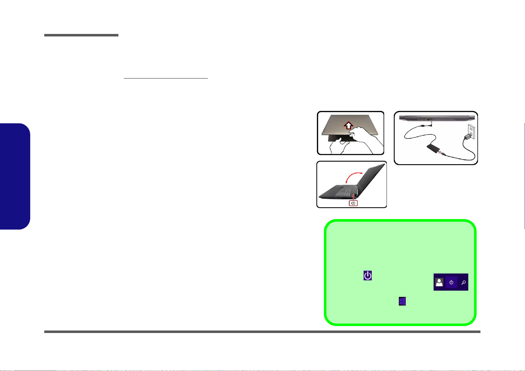
• Attach the AC/DC adapter cord to the DC-In jackon the rear
of the computer, then plug the AC power cord into an outlet,
and connect the AC power cord to the AC/DC adapter. The
battery will now be unlocked.
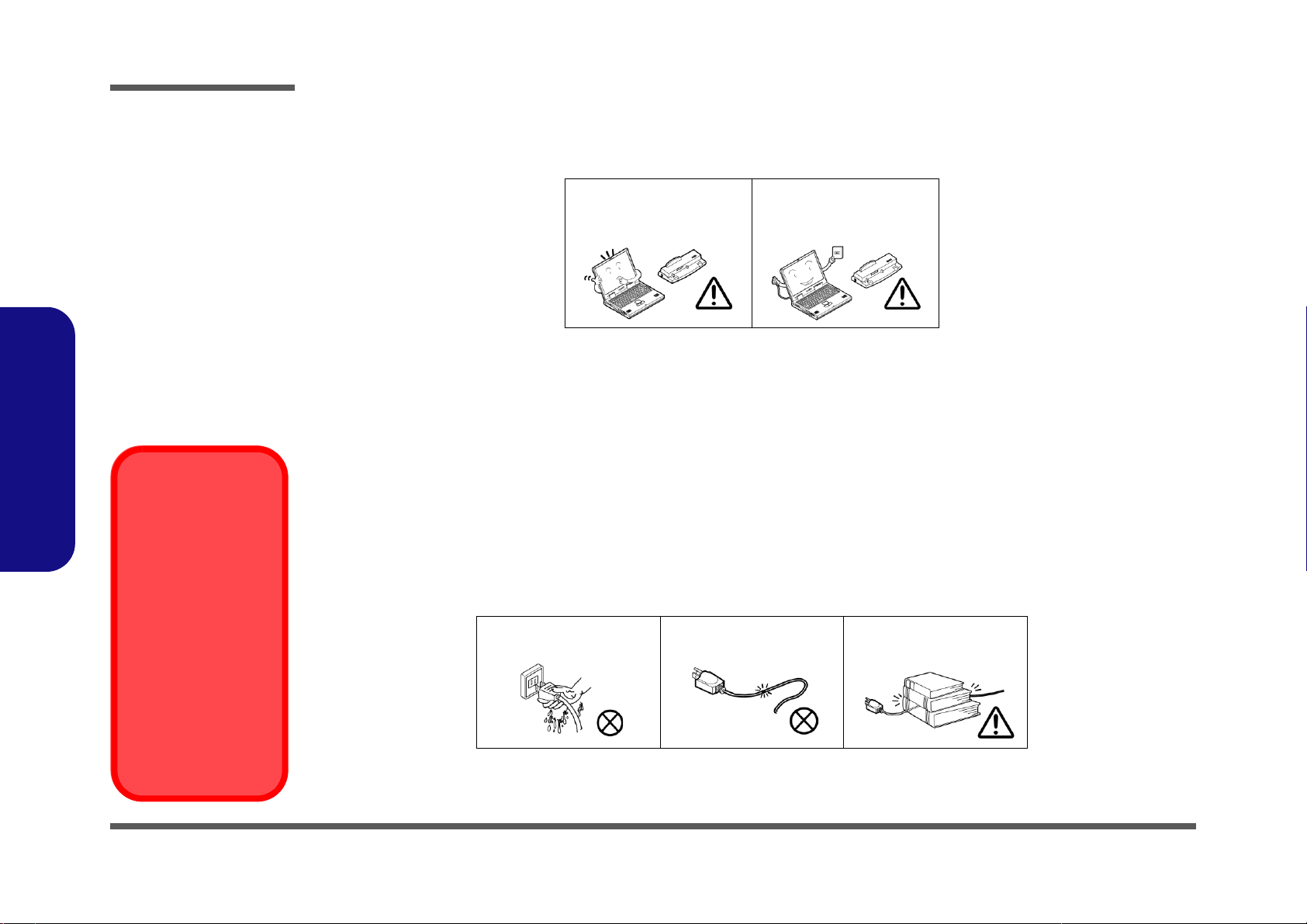
6. Use one hand to raise the
lid/LCD to a comfortable viewing
angle
(do not exceed 130 degrees)
;
use the other hand (as
illustrated in Figure 1) to support the base of the computer
(Note: Never lift the computer by the lid/LCD).
7. Press the power button to turn the computer “on”.
Figure 1
Opening the Lid/LCD/
Computer with AC/DC
Adapter Plugged-In
130°
Shut Down
Note that you should always shut your computer down by
choosing the Shut down command in Windows (see be-
low). This will help prevent hard disk or system problems.
Click the icon in the Start Screen and
choose Shut down from the menu.
Or
Right-click the Start button at the bottom of the Start
Screen or the Desktop and choose Shut down or sign out
> Shut down from the context menu.

Preface
IX
Preface
Contents
Introduction ..............................................1-1
Overview .........................................................................................1-1
Specifications ..................................................................................1-2
External Locator - Top View with LCD Panel Open ......................1-4
External Locator - Front & Right Side Views .................................1-5
External Locator - Left Side & Rear View .....................................1-6
External Locator - Bottom View .....................................................1-7
Mainboard Overview - Top (Key Parts) .........................................1-8
Mainboard Overview - Bottom (Key Parts) ....................................1-9
Mainboard Overview - Top (Connectors) .....................................1-10
Mainboard Overview - Bottom (Connectors) ...............................1-11
Disassembly ...............................................2-1
Overview .........................................................................................2-1
Maintenance Tools ..........................................................................2-2
Connections .....................................................................................2-2
Maintenance Precautions .................................................................2-3
Disassembly Steps ...........................................................................2-4
Removing the Battery ......................................................................2-5
Removing the Keyboard ..................................................................2-6
Removing the Hard Disk Drive .......................................................2-7
Removing the System Memory (RAM) ..........................................2-9
Removing the M.2 SSD Module ...................................................2-10
Removing the Wireless LAN Module ...........................................2-11
Wireless LAN, Combo Module Cables .........................................2-12
Removing the CCD .......................................................................2-13
Part Lists ..................................................A-1
Part List Illustration Location ........................................................A-2
Top .................................................................................................A-3
Bottom ............................................................................................A-4
Main Board ................................................................................... A-5
HDD .............................................................................................. A-6
LCD ............................................................................................... A-7
Schematic Diagrams.................................B-1
System Block Diagram ...................................................................B-2
Processor 1/6 ...................................................................................B-3
Processor 2/6 ...................................................................................B-4
Processor 3/6 ...................................................................................B-5
Processor 4/6 ...................................................................................B-6
Processor 5/6 ...................................................................................B-7
Processor 6/6 ...................................................................................B-8
DDR4 CHA SO-DIMM ..................................................................B-9
DDR4 CHB SO-DIMM ................................................................B-10
VGA PCI Express .........................................................................B-11
GPU Frame Buffer A/B ................................................................B-12
Frame Buffer A .............................................................................B-13
Frame Buffer A .............................................................................B-14
Frame Buffer B .............................................................................B-15
Frame Buffer B .............................................................................B-16
GPU Frame Buffer C/D ................................................................B-17
Frame Buffer C .............................................................................B-18
Frame Buffer C .............................................................................B-19
GPU Decoupling 1 ........................................................................B-20
GPU Decoupling 2 ........................................................................B-21
Straps and XTAL ..........................................................................B-22
IFP I/O Interface ...........................................................................B-23
Misc - GPIO, I2C and ROM .........................................................B-24
NVIDIA Power Sequence .............................................................B-25
GPU NVVDD, FBVDDQ ............................................................B-26
GPU GND .....................................................................................B-27

Preface
X
Preface
mDP ..............................................................................................B-28
Panel, Inverter ..............................................................................B-29
HDMI ...........................................................................................B-30
PCH 1/9 ........................................................................................B-31
PCH 2/9 ........................................................................................B-32
PCH 3/9 ........................................................................................B-33
PCH 4/9 ........................................................................................B-34
PCH 5/9 ........................................................................................B-35
PCH 6/9 ........................................................................................B-36
PCH 7/9 ........................................................................................B-37
PCH 8/9 ........................................................................................B-38
PCH 9/9 ........................................................................................B-39
M.2 Card .......................................................................................B-40
M.2 WLAN+BT, PCIE 4X SSD ..................................................B-41
USB Charger ................................................................................B-42
Card Reader / LAN RTL8411B ...................................................B-43
HDD, Click TP, Audio, Hall Con. ...............................................B-44
LED, CCD, TPM, Power SW Con. .............................................. B-45
KBC-ITE IT5570 .........................................................................B-46
RGB KB .......................................................................................B-47
5V, 5VS, 3.3V, 3.3VS ..................................................................B-48
VDD1.05V, VCCIO .....................................................................B-49
VDD3, VDD5 ...............................................................................B-50
DDR 1.2V / 0.6VS, 2.5V .............................................................B-51
VCore Output Stage .....................................................................B-52
VCC_Core & VCCGT .................................................................B-53
1.05DX_VCCSTG/VCCSFR_OC ...............................................B-54
VCCGT & VCCSA Output Stage ................................................B-55
AC_In, Charger ............................................................................B-56
NVVDD1 .....................................................................................B-57
NVVDD2 .....................................................................................B-58
PEX_VDD ....................................................................................B-59
FBVDDQ ......................................................................................B-60
1V8_RUN/AON ...........................................................................B-61
Audio Board ..................................................................................B-62
NH50 PW Board ...........................................................................B-63
Hall Sensor Board .........................................................................B-64
Click Board ...................................................................................B-65
LED Board ....................................................................................B-66
NH70 PW Board ...........................................................................B-67
Power Sequence ............................................................................B-68

Introduction
Overview 1 - 1
1.Introduction
Chapter 1: Introduction
Overview
This manual covers the information you need to service or upgrade the NH77DCQ / NH79DCQ / NH77DDW series
notebook computer. Information about operating the computer (e.g. getting started, and the Setup utility) is in the User’s
Manual. Information about dri-vers (e.g. VGA & audio) is also found in the User’s Manual. The manual is shipped with
the computer.
Operating systems (e.g. Windows 10, etc.) have their own manuals as do application softwares (e.g. word processing and
database programs). If you have questions about those programs, you should consult those manuals.
The NH77DCQ / NH79DCQ / NH77DDW series notebook is designed to be upgradeable. See Disassembly on page 2
- 1 for a detailed description of the upgrade procedures for each specific component. Please take note of the warning and
safety information indicated by the “” symbol.
The balance of this chapter reviews the computer’s technical specifications and features.

Introduction
1 - 2 Specifications
1.Introduction
Specifications
Latest Specification Information
The specifications listed here are correct at the
time of sending them to the press. Certain items
(particularly processor types/speeds) may be
changed, delayed or updated due to the manu-
facturer's release schedule. Check with your
service center for more details.
CPU
The CPU is not a user serviceable part. Ac-
cessing the CPU in any way may violate your
warranty.
Processor Options
Intel® Core™ i7 Processor
i7-10875H (2.30GHz)
16MB Smart Cache, 14nm, DDR4-2933MHz, TDP 45W
i7-10750H (2.60GHz)
12MB Smart Cache, 14nm, DDR4-2933MHz, TDP 45W
Intel® Core™ i5 Processor
i5-10300H (2.50GHz)
8MB Smart Cache, 14nm, DDR4-2933MHz, TDP 45W
Core Logic
Mobile Intel® HM470 Express Chipset
BIOS
128Mb SPI Flash ROM
INSYDE BIOS
Memory
Dual Channel DDR4
Two 260 Pin SO-DIMM Sockets
Supporting up to 3200MHz DDR4 Memory
Memory Expandable up to 32GB
Compatible with 4GB, 8GB or 16GB Modules
(The real memory operating frequency depends on the FSB
of the processor.)
Storage
One changeable 2.5" 7.0mm (h) SATA (Serial) Hard Disk
Drive/Solid State Drive (SSD)
(Factory Option) One M.2 2280 SATA Solid State Drive
(SSD)
Or
(Factory Option) Two PCIe Gen3 x4 M.2 2280 SSDs sup-
porting RAID level 0/1
Audio
High Definition Audio Compliant Interface
Sound Blaster™ Cinema 6
Built-In Array Microphone
Two Speakers
LCD Options
17.3" (43.94cm), 16:9, FHD (1920x1080)
Video Adapter
Intel® Integrated GPU and NVIDIA® Discrete GPU
Supports Microsoft Hybrid Graphics
Intel Integrated GPU
Intel® UHD Graphics 630
Dynamic Frequency
Intel Dynamic Video Memory Technology
Microsoft DirectX®12 Compatible
NVIDIA® Discrete GPU
NVIDIA® GeForce GTX 1660Ti
6GB GDDR6 Video RAM on board
Microsoft DirectX® 12 Compatible
Security
Security (Kensington® Type) Lock Slot
BIOS Password
Intel® PTT for Systems Without TPM Hardware
(Factory Option) TPM 2.0
Keyboard
Full-size Multi-Color LED Keyboard (with Numeric Keypad)
Or
(Factory Option) Full Size Full Color “Per Key” LED Key-
board (with Numeric Keypad)

Introduction
Specifications 1 - 3
1.Introduction
Pointing Device
Built-in Touchpad (with Microsoft PTP Multi Gesture & Scroll-
ing Functionality)
Card Reader
Embedded Multi-In-1 Card Reader
MMC (MultiMedia Card) / RS MMC
SD (Secure Digital) / Mini SD / SDHC/ SDXC
M.2 Slots
Slot 1 for Combo WLAN and Bluetooth Module
Slot 2 for SATA or PCIe Gen3 x4 SSD
Slot 3 for PCIe Gen3 x4 SSD only
Interface
One DisplayPort 1.3 over USB 3.1 Gen 2 Type-C Port
One USB 3.1 Gen 2 Type-A Port
One USB 3.0 (USB 3.1 Gen 1) Type-A Port
One USB 2.0 Port
One Mini DisplayPort 1.2
One HDMI-Out Port
One Microphone-In Jack
One 2- In-1 Audio Jack (Headphone and Microphone)
One RJ-45 LAN
Jack
One DC-In Jack
USB 3.1 Gen 2
Note that when a single USB device is plugged
in to a USB 3.1 Gen 2 port the data transfer
speed will be 10Gbps, however whentwo devic-
es are plugged in to both USB 3.1 Gen 2 ports,
this bandwidth will be shared between the ports.
Communication
Built-In 10/100/1000Mb Base-TX Ethernet LAN
1.0M HD PC Camera Module
WLAN/ Bluetooth M.2 Modules:
(Factory Option) Intel® Dual Band Wireless-AC 9260 Wire-
less LAN (802.11ac) + Bluetooth
(Factory Option) Intel® Dual Band Wireless-AC 9560 Wire-
less LAN (802.11ac) + Bluetooth
(Factory Option) Intel® Dual Band Wireless-AC 9462 Wire-
less LAN (802.11ac) + Bluetooth
(Factory Option) Qualcomm® Atheros Killer™ Wireless-AC
1550i Wireless LAN (802.11ac) + Bluetooth
Environmental Spec
Temperature
Operating: 5°C - 35°C
Non-Operating: -20°C - 60°C
Relative Humidity
Operating: 20% - 80%
Non-Operating: 10% - 90%
Power
Removable 4 Cell Smart Lithium-Ion Battery Pack, 48.96WH
Full Range AC/DC Adapter
AC Input: 100 - 240V, 50 - 60Hz
DC Output: 19.5V, 9.23A (180W)
Dimensions & Weight
399.9mm (w) * 282.2mm (d) * 29.2mm (h)
2.5kg (Barebone with 48.96WH Battery)

Introduction
1 - 4 External Locator - Top View with LCD Panel Open
1.Introduction
External Locator - Top View with LCD Panel Open
Figure 1
Top View
1. PC Camera
2. *PC Camera LED
*When the PC
camera is in use,
the LED will be
illuminated.
3. Built-In Array
Microphone
4. LCD
5. Power Button
6. Keyboard
7. Touchpad &
Buttons
2 1
7
6
4
5
33

Introduction
External Locator - Front & Right Side Views 1 - 5
1.Introduction
External Locator - Front & Right Side Views
Figure 2
Front View
1. LED Indicator
Figure 3
Right Side View
1. USB 3.2 Gen 2
Type-A Port
2. Mini Display Port
1.4
3. Multi-in-1 Card
Reader
4. Vent
FRONT VIEW
1
RIGHT SIDE VIEW
124
3

Introduction
1 - 6 External Locator - Left Side & Rear View
1.Introduction
External Locator - Left Side & Rear View
/
Figure 4
Left Side View
1. Security Lock Slot
2. Vent
3. USB 3.2 Gen 1
Type-A Port
4. USB 2.0 Port
5. Microphone-In
Jack
6. 2-In-1 Audio Jack
(Headphone and
Microphone)
LEFT SIDE VIEW
123 4 5 6
Figure 5
Rear View
1. Vent
2. Display Port 1.4
over USB 3.2 Gen
2 Type-C Port
3. HDMI-Out Port
4. RJ-45 LAN Jack
5. DC-In Jack
REAR VIEW
12 3 4 5

Introduction
External Locator - Bottom View 1 - 7
1.Introduction
External Locator - Bottom View
Overheating
To prevent your com-
puter from overhea-
ting, make sure no-
thing blocks any vent
while the computer is
in use.
2
1
3
2
3
2
2
2
Figure 6
Bottom View
1. Battery
2. Vent
3. Speakers

Introduction
1 - 8 Mainboard Overview - Top (Key Parts)
1.Introduction
Mainboard Overview - Top (Key Parts)
Figure 7
Mainboard Top
Key Parts
1. KBC-ITE IT5570
1
This manual suits for next models
2
Table of contents
Other Clevo Laptop manuals