Introduction
1 - 2 Specifications
1.Introduction
Specifications
Latest Specification Information
The specifications listed here are correct at the
time of sending them to the press. Certain items
(particularly processor types/speeds) may be
changed, delayed or updated due to the manu-
facturer's release schedule. Check with your
service center for more details.
CPU
The CPU is not a user serviceable part. Ac-
cessing the CPU in any way may violate your
warranty.
Processor Options
Intel® Core™ i7 Processor
i7-4500U (1.80GHz)
4MB L3 Cache, 22nm, DDR3L-1600MHz, TDP 15W
Intel® Core™ i5 Processor
i5-4200U (1.60GHz)
3MB L3 Cache, 22nm, DDR3L-1600MHz, TDP 15W
Intel® Core™ i3 Processor
i3-4010U (1.70GHz)
3MB L3 Cache, 22nm, DDR3L-1600MHz, TDP 15W
BIOS
96Mb SPI Flash ROM
AMI BIOS
Memory
Two 204 Pin SO-DIMM Sockets Supporting DDR3L
1600MHz Memory
Memory Expandable up to 16GB
(The real memory operating frequency depends on the
FSB of the processor.)
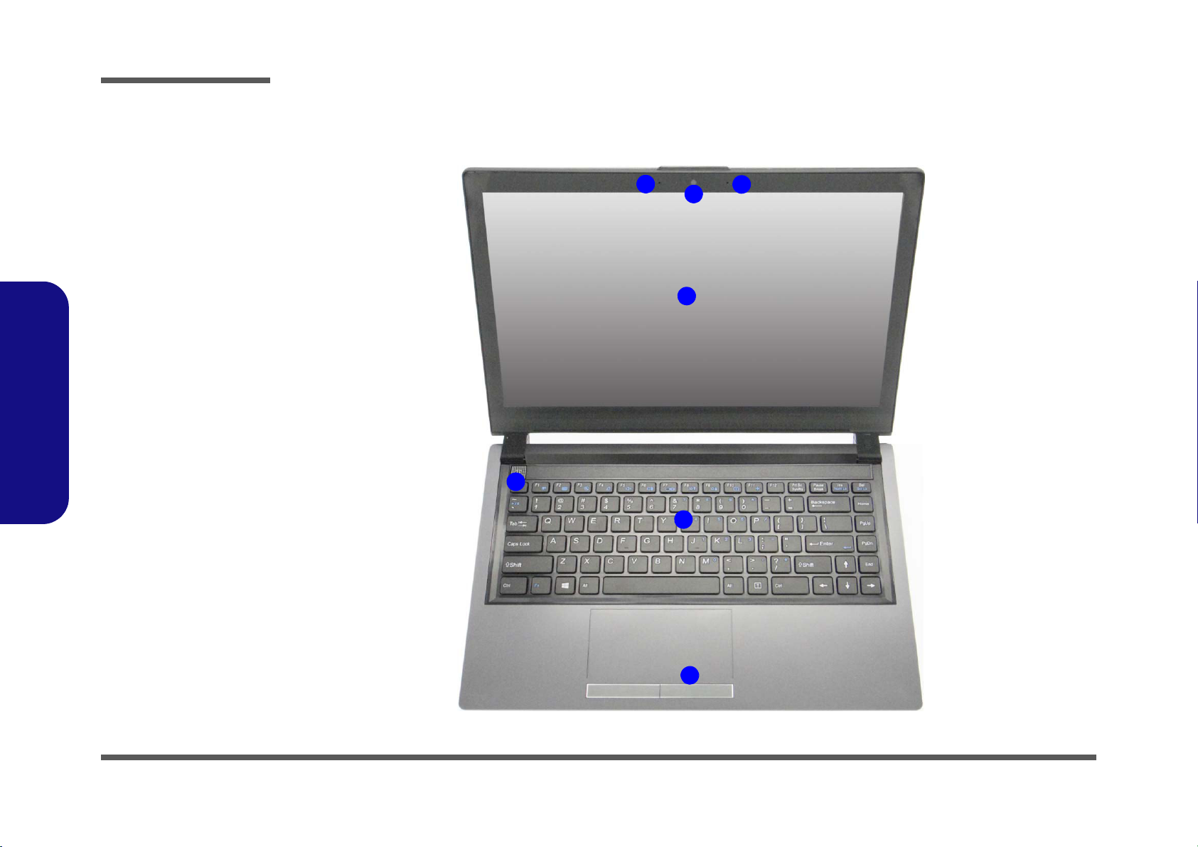
LCD
14" (35.56cm) HD/ HD+/ FHD (Thickness: 3.2mm)
Multi Touch
Storage
One Changeable 2.5" 7.0mm (h) SATA HDD
(Factory Option) One mSATA Solid State Drive (SSD)
Audio
High Definition Audio Compliant Interface
2 * Built-In Speakers
Built-In Microphone
Security
Security (Kensington® Type) Lock Slot
BIOS Password
(Factory Option) TPM 1.2
Keyboard
“WinKey” keyboard
Pointing Device
Built-in Touchpad
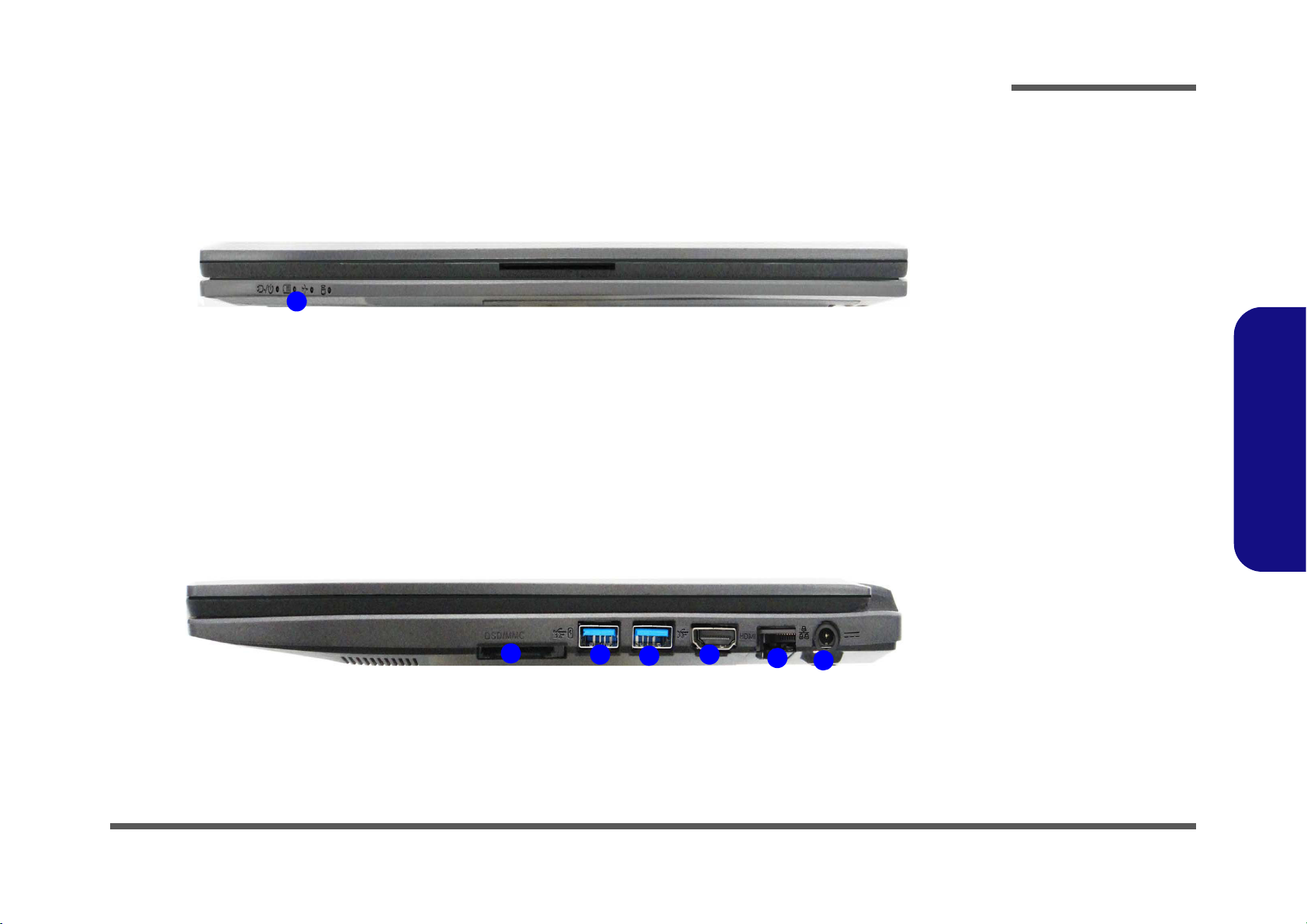
Interface
Two USB 3.0 Ports
One HDMI-Out Port
One Headphone-Out Jack
One Microphone-In Jack
One RJ-45 LAN Jack
One DC-in Jack
Mini Card Slot
Slot 1 for WLAN Module or WLAN and Bluetooth Combo
Module
(Factory Option) Slot 2 for 3G Module or mSATA SSD
Video Adapter
Intel HD Graphics 4400
Dynamic Frequency (Intel Dynamic Video Memory Tech-
nology for up to 1.7GB)
Microsoft DirectX® 11 Compatible
Card Reader
Embedded Multi-in-1 Push-Push Card Reader
MMC (MultiMedia Card) / RS MMC
SD (Secure Digital) / Mini SD / SDHC/ SDXC