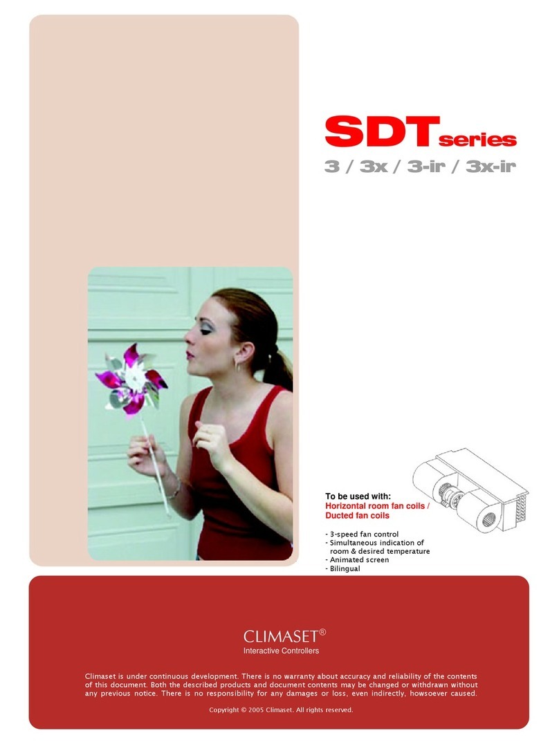
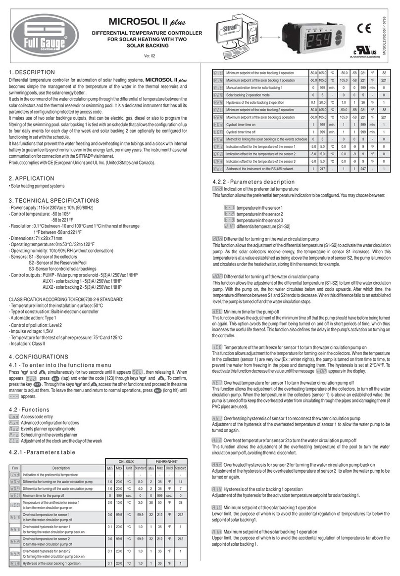
CLIMASET SDT Series User manual

SDTseries
ss/ss – ir
To be used with:
Vertical room fan coils
- Simultaneous indication of
room & desired temperature
- Animated screen
- Bilingual
CLIMASET®
Interactive Controllers
Climaset is under continuous development. There is no warranty about accuracy and reliability of the contents
of this document. Both the described products and document contents may be changed or withdrawn without
any previous notice. There is no responsibility for any damages or loss, even indirectly, howsoever caused.
Copyright © 2005 Climaset. All rights reserved.

User’s Guide

CLIMASET
3
Contents .
1. Your Climaset........................................................................................................................................... 4
2. Wall mounted unit .................................................................................................................................... 4
2.1. Keys and infrared sensor ................................................................................................................... 4
2.2. Screen elements ................................................................................................................................ 5
2.3. Using the menu................................................................................................................................. 5
2.4. Menu functions ................................................................................................................................. 6
2.5. Back light .......................................................................................................................................... 6
3. Remote controller unit (SDT ss-ir only) ..................................................................................................... 7
3.1. Installing batteries for remote controller............................................................................................ 7
3.2. Keys.................................................................................................................................................. 8
3.3. Screen elements ................................................................................................................................ 8
3.4. List of status bar messages ............................................................................................................... 9
4. Installation guide...................................................................................................................................... 9
4.1. Mounting the wall mounted unit ........................................................................................................ 9
4.2. Proper wiring technique for the wall mounted unit ........................................................................... 10
4.3. Engaging the wall mounted unit ...................................................................................................... 10
4.4. Wall mounted unit connectors ......................................................................................................... 10
4.5. Wiring diagram................................................................................................................................ 11
5. Care and maintenance ............................................................................................................................ 11
6. Specifications ......................................................................................................................................... 12

CLIMASET
4
1. Your Climaset .
Climaset SDT ss / ss-ir series are designed to work in conjunction with vertical room fan coils to maintain the
room air condition at the comfort level and consist of the following units:
nWall mounted unit
oRemote controller (Optional SDT ss-ir only)
2. Wall mounted unit .
The wall mounted unit has the following functions:
1. Measurement of room temperature.
2. Interaction with user to adjust the set points.
3. Interaction with the remote controller (SDT ss-ir only).
4. Interaction with fan coil unit to turn the fan on/off according to the temperature difference or user
command.
2.1. Keys and infrared sensor
n"Up" and o"Down"
Use these keys to scroll the menus.
p"Right" and q"Left"
Use these keys to adjust the values in each menu item.
r"Power"
On/Off switch.
s"Infrared sensor" (SDT ss-ir only)
Intended to receive the remote controller commands.

CLIMASET
5
2.2. Screen elements
nRoom temperature: Indicates the current room temperature.
oDesired temperature: Your desired room temperature.
pPower status:
Air conditioner apparatus is on.
Air conditioner apparatus is off.
qSeason setting:
The device is adjusted to work in summer.
The device is adjusted to work in winter.
rFan status: If the icon rotates, it indicates that, in case the fan coil selector key is not positioned to off the
fan is working with the speed adjusted with the selector key of the fan coil. If it is still, it indicates the fan is
switched off.
sAnimated icon: It reacts based on temperature difference between the "Desired" and the "Room".
The left icon appears when the room temperature is above the comfort range. Comfort range is up to 1°c
above the "Desired" in summer or up to 1°c below the "Desired" in winter.
The middle icon indicates that the room temperature is in the comfort range.
The right icon shows the room temperature is below the comfort.
tStatus bar: Indicates the” Menu item" which you wish to adjust. Use” Up" or "Down" keys to surf through
these menus (Refer to section 2.1 for "Up" and” Down" keys).
2.3. Using the menu
2.3.1. Accessing a menu function
Scroll with the "Up" or "Down" keys to access the desired menu function. Use "Right" or "Left" keys to adjust
the set points (Refer to Section 2.1 for "Up", "Down", "Right" and "Left" keys)(Refer to section 2.4 on adjusting
set points and their functions).
2.3.2. List of menu functions
1. Desired temperature
2. Season settings
3. English / Local

CLIMASET
6
2.4. Menu functions
2.4.1. Desired temperature (Menu item 1)
It is the temperature which you like to maintain your room. The standard set point for comfort condition in
the residential zones is 24°c, but you can set a higher or lower temperature if you wish.
The minimum allowable temperature is 16°c and the maximum is 31°c. You can use "Right" key to increase
the value or "Left" key to decrease it (Refer to section 2.1 for "Right" and "Left" keys). As you change the value
the result appears on the desired temperature section of the screen (Refer to section 2.2 to find the "Desired
temperature" on the screen).
Note: If you set a value much lower than 24°c in summer or much higher in winter, it may cause your air
conditioning device to work continuously. The set point which may cause the device to work continuously
depends on outside temperature, air conditioning device heating and cooling capacity, and some other
factors related to your building.
Note: If you set a value much higher than 24°c in summer or much lower in winter, it may cause your air
conditioning device not to start working. For a brief on the conditions which cause such a behavior refer to
the previous note.
2.4.2. Season settings (Menu item 2)
Set the current season for the controller to work properly.
Setting the "summer" in this field causes the controller to switch the air conditioner on if the room
temperature is higher than desired.
In "winter" mode, the air conditioner switches on if the room temperature is lower than the desired.
Use "Right" or "Left" key to adjust the current season. The result appears at "Season setting" section of the
screen (Refer to section 2.2 to find "Season setting" section of the screen and section 2.1 for "Right" and
"Left" keys).
Notice: Not setting this field correctly may cause your air conditioner not to start working.
2.4.3. English / Local (Menu item 3)
It indicates language of the items of the status bar. If "English" is selected, all menu functions will appear in
English. If local is selected, all menu functions of the status bar will appear in your local language.
2.5. Back light
Pressing any keys on the wall mounted unit turns on the back light for several seconds. It enhances reading
during the night.

CLIMASET
7
3. Remote controller unit (SDT ss-ir only) .
The remote controller utilizes infrared light waves to send the commands to the wall mounted unit. The light
waves are effective at the maximum distance of 16 meters. The viewing angle for the remote controller is 30
degree. It means the wall mounted unit can still sense the commands even if remote controller deflects up to
30 degree from the wall mounted unit infrared sensor.
Note: All remote controllers use the same code, so you may use a single remote control with several wall
mounted units.
Notice: Blocking the infrared lamp on the top of remote controller significantly reduces the range.
3.1. Installing batteries for remote controller
Locate the small latch on the battery compartment cover and push gently the latch in the direction of the
arrow as illustrated below.
The cover releases. Lift off the cover to reveal the inner battery compartment.
Install two new AAA-size 1.5-volt alkaline, lithium or NiCad batteries with correct polarity following the
illustration inside the battery compartment.
Warning: Mixing different battery types may cause explosion. Install same battery types each time you change
them.
Replace the battery cover by inserting the prong into the slot at the bottom of the battery compartment and
then pushing the cover until the latch snaps closed.

CLIMASET
8
Press the "Wake up" key (Refer to section 3.2 for the "Wake up" key). The "Stand by" screen appears and the
remote controller is functional (Refer to section 3.3.1 for "Stand by" screen).
Notice: Do not place objects on top of the remote control after installation of the batteries. Pressing the keys
for an extended period of time reduces the battery life.
3.2. Keys
n"Up":
Use this key to increase the desired temperature.
o"Down":
Use this key to decrease the desired temperature.
p”Right":
Use this key to switch on the "power status" setting.
q”left":
Use this key to switch off the "power status" setting.
r"Send":
Use this key to transmit settings to the "Wall mounted" unit. After it recognizes
the commands, it responses by a beep sound. If the beep sound is not heard,
you should repeat the transmission by pressing the "Send" key again.
Notice: If the beep sound is not heard after several attempts, it may be one of
the following cases:
•You may too much far from the "Wall mounted" unit. Step toward the
"Wall mounted" unit and try again.
•The deflection between remote controller and the "Wall mounted" unit is
above the maximum allowable. Point the remote controller toward the
"Wall mounted" unit.
•Batteries should be replaced with new ones.
•If none of the above is the case, please contact your dealer for customer service.
s"Wake up": Activates the remote controller. The remote controller is equipped with auto power off feature in
order to minimize power consumption. If you do not push any key for 3 minutes, it goes to "Sleep” mode.
3.3. Screen elements
3.3.1. Stand by screen
nDesired temperature: Your desired room temperature.
oPower status:
Air conditioner apparatus is on.
Air conditioner apparatus is off.
pFan status: If the icon rotates, it indicates that, in case the fan coil selector key is not positioned to off, the
fan is working with the speed adjusted with the selector key of the fan coil. If it is still, it indicates the fan is
switched off.
qStatus bar: It indicates messages about the last key you just pressed for several seconds.

CLIMASET
9
3.3.2. Good bye screen
If the remote controller is not used for about 3 minutes, it goes to the "sleep mode". Before it sleeps,” Good
bye screen" will appear for some seconds.
3.4. List of status bar messages
n"Ready": Remote controller is ready for adjustments.
o"Temp. raised": By pressing "Up" key you have increased the "Desired" temperature.
p"Temp. dropped": By pressing "Down" key you have decreased the "Desired" temperature.
q"Power turned on": Power status is switched on by pressing the "Right" key.
r"Power turned off": Power status is switched off by pressing the "Left" key.
s"Not allowed": The message appears if you try to set the desired temperature above 31°c or below 16°c or
by pressing "Right" key when the power status is on or "Left" key when the power status is off.
4. Installation guide .
4.1. Mounting the wall mounted unit
Position the mounting plate on the wall. Level the mounting plate. Use a pencil to mark the mounting holes.
Remove the plate from the wall and drill 3/16" holes in wall. Tap anchors into drilled holes. Reposition the
plate and loosely insert two mounting screws into the holes. Level the plate for appearance. Tighten
mounting screws.

CLIMASET
10
4.2. Proper wiring technique for the wall mounted unit
Please refer to the sketch below for the proper wiring technique. Also refer to section 4.5 for arrangement of
the wires.
4.3. Engaging the wall mounted unit
Engage tabs at the top of the units and the wall plate. Gently press lower edge of the case to latch.
To remove the "Wall mounted unit" from the wall, the top should be pulled out first.
4.4. Wall mounted unit connectors
Connector
Unit Description Input /
Output
Electrical
Characteristics
1
2
3
Phase
Null
Fan phase wire
Input
Input
Output
AC220V/50Hz
Null
AC220V/50Hz

CLIMASET
11
4.5. Wiring diagram
Please refer to sketch below for the wirings.
5. Care and maintenance .
Care should be taken about the following items which may cause warranty obligation.
1. Keep the remote controller unit out of reach of children.
2. Do not use detergents or any chemicals to clean the Climaset. It may cause damages to electronic parts
inside.
3. Climaset is designed to be used for residential comfort. Do not store it in hot or cold areas. Also it should
not be stored in dirty or dusty environment.
4. Do not attempt to open any part of the Climaset. There is no part inside which you can service it. Ask your
local dealer for services, if necessary.
5. Do not drop the remote controller. Take care in handling remote controller.
6. Keep the Climaset dry. Moisture can cause irreparable damages on electronic parts.

CLIMASET
12
6. Specifications .
Please refer to sketch below for the wirings.
Other manuals for SDT Series
1
This manual suits for next models
2
Table of contents
Other CLIMASET Temperature Controllers manuals
