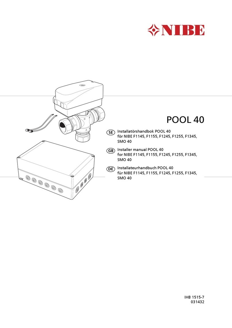
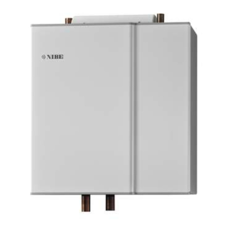
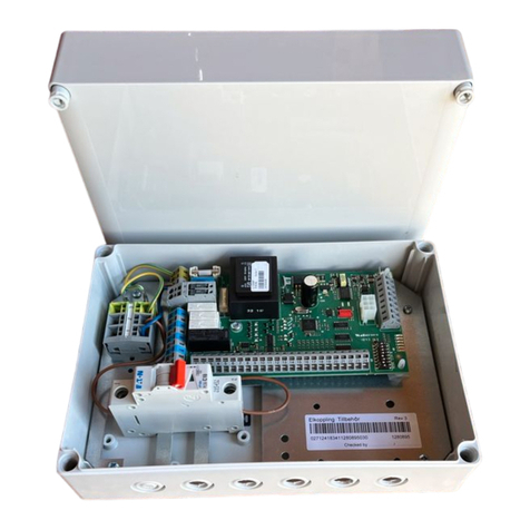
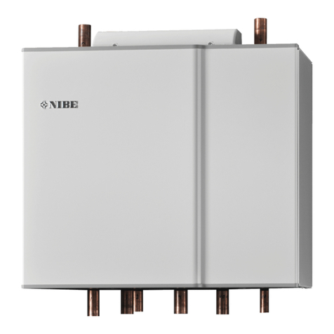
Nibe POOL 40 User guide

LEK
POOL 40
Installatörshansbok POOL 40
för NIBE F1145, F1245
SE
Installer manual POOL 40
for NIBE F1145, F1245
GB
Installateurhandbuch POOL 40
für NIBE F1145, F1245
DE
IHB 0945-2
031432


Allmänt
POOL 40 är ett tillbehör för att möjliggöra pooluppvärm-
ning med F1145/F1245. Värmepumpen styr växelventilen
(QN19), poolcirkulationspumpen (GP9) och ev. värmekret-
sens cirkulationspump (GP10) via POOL 40.
Innehåll
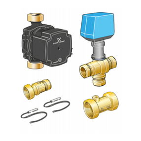
Buntband4st
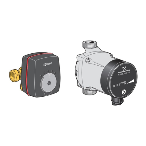
Ställdon växelventil1st
Växelventil1st
Kit för tillbehörskort1st
Värmeledningspasta2st
Aluminiumtejp1st
Isoleringstejp1st
Temperaturgivare2st
Komponentplacering
LEK
AA5-X4
AA5-S2
AA5-X2
AA5-X9
X1
FA1
AA5-F1
AA5
AutomatsäkringFA1
Anslutningsplint, spänningsmatningX1
TillbehörskortAA5
Anslutningsplint, givare och extern blockeringAA5-X2
Anslutningsplint, kommunikationAA5-X4
Anslutningsplint, cirkulationspumpar och växelventilAA5-X9
Anslutningsplint, växelventilAA5-X10
DIP-switchAA5-S2
FinsäkringAA5-F1
3
Svenska, Installatörshandbok - POOL 40
SE

Röranslutning
Allmänt
När F1145/F1245 är dockad mot pool, måste värmekret-
sen förses med en yttre cirkulationspump. Orsaken till
detta är att under poolladdning är det värmepumpens
interna cirkulationspump som håller uppe flödet genom
poolvärmeväxlaren. Den extra/yttre cirkulationspumpen
(GP10) håller flödet uppe i värmekretsen, för att framled-
ningsgivaren (BT25) ska kunna mäta temperaturen kor-
rekt.
Växelventil
႑Montera växelventilen (QN19) med port AB som in-
kommande framledning från värmepumpen, port A
mot poolen och port B mot värmesystemet. Montera
den så att port AB är öppen mot port B när motorn
är i viloläge. Vid signal öppnar port AB mot port A.
A
B
AB
Temperaturgivare
႑Poolgivaren (BT51) placeras på returledningen från
poolen.
႑Den externa framledningsgivaren (BT25) placeras på
framledningen till klimatsystemet, efter cirkulations-
pumpen (GP10).
K
Temperaturgivarna monteras med buntband tillsammans
med värmeledningspasta och aluminiumtejp. Därefter
skall de isoleras med medföljande isolertejp.
OBS!
Givar- och kommunikationskablar får ej förläggas
i närheten av starkströmsledning.
Funktion
Uppvärmning av poolen prioriteras enligt valda inställning-
ar i värmepumpen.
Om poolgivaren (BT51) inte är ansluten tillåts poolladd-
ningen inte att starta.
Värmebärarflödet justeras så att temperaturdifferensen
över poolvärmeväxlaren är 10 – 15 °C. Inställningen görs
i meny 5.1.11.
4
SE

Principschema
Förklaring
VärmepumpEB100Temperaturgivare, utomhusBT1
Ackumulatortank med varmvattenslingaCP1Framledningsgivare, extra klimatsystemBT2
ExpansionskärlCM1Returledningsgivare, extra klimatsystemBT3
SäkerhetsventilFL2Temperaturgivare, varmvattenBT6
AvstängningsventilQM31,
QM32
Extern temperaturgivare, framledningBT25
SmutsfilterHQ1, HQ4Temperaturgivare, poolBT51
BackventilRM2PoolsystemCL11
Cirkulationspump, klimatsystemGP10Växelventil, poolQN19
Extra klimatsystemEP21Tillbehörskort, poolAA5
Cirkulationspump, extra klimatsystemGP20Cirkulationspump, poolGP9
Shuntventil, extra klimatsystemQN25Värmeväxlare, poolEP5
Principschema F1145 med POOL 40
-QM31
-FL2
-QM32
-HQ1
-CM1
-BT1
-EB100
F1145
-BT25
-RM2
-GP10
-EP5
-CL11-GP9 -CL11-BT51 POOL
-HQ4
-CL11-AA5
-CL11-QN19
BA
AB
-BT6
-CP1
5
SE

Principschema F1145 med POOL 40 och extra klimatsystem
-QM31
-FL2
-QM32
-HQ1
-CM1
-BT1
-EB100
F1145
-BT25
-RM2
-GP10
-EP5
-CL11-GP9 -CL11-BT51 POOL
-HQ4
-CL11-QN19
-CL11-AA5
BA
AB
-BT6
-CP1
-GP20
-BT3
-BT2
-QN11
-EP21
Principschema F1245 med POOL 40
-BT1
-QM31
-QM32
-HQ1
F1245
-EB100
-FL2
-CM1
-BT25
-RM2
-GP10
-EP5
-CL11-GP9 -CL11-BT51 POOL
-HQ4
-CL11-AA5
-CL11-QN19
BA
AB
6
SE

Principschema F1245 med POOL 40 och extra klimatsystem
-BT1
-QM31
-QM32
-HQ1
F1245
-EB100
-FL2
-CM1
-BT25
-RM2
-GP10
-EP5
-CL11-GP9 -CL11-BT51 POOL
-HQ4
-CL11-QN19
-CL11-AA5
BA
AB
-GP20
-BT3
-BT2
-QN11
-EP21
7
SE

Elinkoppling
OBS!
All elektrisk inkoppling skall ske av behörig
elektriker.
Elektrisk installation och ledningsdragning skall
utföras enligt gällande bestämmelser.
F1145/F1245 ska vara spänningslös vid installa-
tion av POOL 40.
Elscheman finns i slutet av denna monteringsanvisning.
Anslutning av matning
Anslut spänningsmatningen till plint X1 enligt bild.
3
2
1N
230V 50Hz-X1
L
PE
Anslutning av kommunikation
Det första tillbehörskortet ska anslutas direkt till värme-
pumpens plint AA3-X4. Vid flera tillbehörskort ska de
efterföljande korten anslutas i serie med föregående kort.
Använd kabeltyp LiYY, EKKX eller likvärdig.
1
2
3
4
5
6
7
8
AA5-X4
15
A
B
GND
A
B
GND
A
B
GND
A
B
GND
A
B
GND
14
13
AA3-X4
1
2
3
4
5
6
7
8
AA5-X4
F1245
AA3-X4
F1145
AA3-X4
Tillbehörskort 1
Tillbehörskort 2
ON
12345678
-X9
-X2
24 20212223 1516171819 1011121314 567891
1
N
L
PE
PE
1
2
3
4
5
6
7
8
2
3
4
5
6
7
8
9
234
-X8
-X4
-X10
-X1
AA5-X4
ON
12345678
-X9
-X2
24 20212223 1516171819 1011121314 567891
1
N
L
PE
PE
1
2
3
4
5
6
7
8
2
3
4
5
6
7
8
9
234
-X8
-X4
-X10
-X1
AA5-X4
F1145/F1245
8
SE

Anslutning av givare och extern blockering
Använd kabeltyp LiYY, EKKX eller likvärdig.
Poolgivare (BT51)
Anslut poolgivaren till AA5-X2:23-24.
Extern blockering (valfritt)
En kontakt kan anslutas till AA5-X2:21-22 för att kunna
blockera pooluppvärmningen. När kontakten sluts bloc-
keras pooluppvärmningen.
345678
-X2
24 20212223 1
7
1819
-X8
BT51
Extern
blockering
AA5
Extern framledningsgivare (BT25)
Anslut framledningsgivaren till AA3-X6:5-6 på ingångs-
kortet i värmepumpen.
AA3-X6
1
2
3
4
5
6
7
8
9
BT25
BT25
$$;
F1245
123456789
BT25
BT25
AA3-X6
$$;
F1145
TÄNK PÅ!
Reläutgångarna på tillbehörskortet får max be-
lastas med 2 A (230 V) totalt.
Anslutning av cirkulationspump, poolkrets
(GP9)
Anslut cirkulationspumpen (GP9) till AA5-X9:8 (230 V),
AA5-X9:7 (N) och X1:3 (PE).
-X9
-X1
1
2
3
4
5
6
7
8
9
-X10
L
N
PE
3
2
1
GP9
AA5
Anslutning av cirkulationspump, klimatsy-
stem (GP10)
Om klimatsystemet inte redan är försett med en extern
pump ska en sådan kopplas in på tillbehörskortet.
Anslut cirkulationspumpen (GP10) till AA5-X9:2 (230 V),
AA5-X9:1 (N) och X1:3 (PE).
GP10
-X1
1
N
L
PE
PE
2
3
4
-X10
-X1
L
N
PE
3
2
1
-X9
-AA5
9
SE

Anslutning av växelventilsmotor (QN19)
Anslut motorn (QN19) till AA5-X9:6 (signal), AA5-X9:5
(N) och AA5-X10:2 (230 V).
-X9
1
2
3
4
5
6
7
8
9
-X10
Svart
Blå
Brun QN19
2
1
AA5
DIP-switch
DIP-switchen på tillbehörskortet ska ställas in enligt ne-
dan.
ON
12345678
-X9
-X2
24 20212223 1516171819 1011121314 567891
1
N
L
PE
PE
1
2
3
4
5
6
7
8
2
3
4
5
6
7
8
9
234
-X8
-X4
-X10
-X1
AA5-S2
ON
12345678
Programinställningar
Programinställningen av POOL 40 kan göras via startgui-
den eller direkt i menysystemet.
Startguiden
Startguiden visas vid första uppstart efter värmepumpsin-
stallationen, men finns även i meny 5.7.
Menysystemet
Om du inte gör alla inställningar via startguiden eller be-
höver ändra någon inställning kan du göra detta i meny-
systemet.
Meny 5.2 - systeminställningar
Aktivering/avaktivering av tillbehör.
Meny 4.1.1 - pool
Aktivering av pooluppvärmning samt inställning av start-
och stopptemperatur.
Meny 5.1.11 - värmebärarpumpshastighet
Inställning av värmebärarpumpens hastighet.
TÄNK PÅ!
Se även Installatörshandboken för F1145/F1245.
10
SE

General
POOL 40 is an accessory that enables pool heating with
F1145/F1245. The heat pump controls the reversing valve
(QN19), pool circulation pump (GP9) and any heating
circuit circulation pumps (GP10) via POOL 40.
Contents
Cable ties4x
Actuator reversing valve1x
Shuttle valve1x
Kit for accessory card1x
Heating pipe paste2x
Aluminium tape1x
Insulation tape1x
Temperature sensor2x
Component positions
LEK
AA5-X4
AA5-S2
AA5-X2
AA5-X9
X1
FA1
AA5-F1
AA5
Miniature circuit-breakerFA1
Terminal block, power supplyX1
Accessory cardAA5
Terminal block, sensors and external blockingAA5-X2
Terminal block, communicationAA5-X4
Terminal block, circulation pumps and reversing valveAA5-X9
Terminal block, reversing valveAA5-X10
DIP switchAA5-S2
Fine-wire fuseAA5-F1
11
English, Installer manual - POOL 40
GB

Pipe connections
General
When F1145/F1245 is docked to pool, the heating circuits
must be supplied with an external circulation pump. This
is because, during pool charging, the internal circulation
pump of the heat pump maintains a flow through the
pool heat exchanger. The extra/external circulation pump
(GP10) keeps the flow up in the heating circuit, so the
flow temperature sensor (BT25) can measure the temper-
ature correctly.
Shuttle valve
႑Install the reversing valve (QN19) with port AB as in-
coming flow line from the heat pump, port A towards
the pool and port B towards the heating system. Install
it so that port AB is open towards port B when the
motor is in standby mode. In the event of a signal
port AB opens towards port A.
A
B
AB
Temperature sensor
႑The pool sensor (BT51) is located on the return line
from the pool.
႑The external flow temperature sensor (BT25) is located
on the flow line to the climate system, after the circu-
lation pump (GP10).
K
Install the temperature sensors with cable ties with the
heat conducting paste and aluminium tape. Then insulate
with supplied insulation tape.
NOTE
Sensor and communication cables must not be
placed near power cables.
12
GB

Function
Heating of the pool is prioritised according to selected
settings in the heat pump.
If the pool sensor (BT51) is not connected, pool charging
is not permitted to start.
The heat medium flow is adjusted so that the temperature
difference over the pool accumulator is 10 - 15°C. The
setting is made in menu 5.1.11.
Outline diagram
Explanation
Heat pumpEB100Temperature sensor, outdoorBT1
Accumulator tank with hot water coilCP1Flow temperature sensor, extra climate systemBT2
Expansion vesselCM1Return line sensor, extra climate systemBT3
Safety valveFL2Temperature sensor, hot waterBT6
Shut-off valveQM31,
QM32
External temperature sensor, flow lineBT25
Particle filterHQ1, HQ4Temperature sensor, poolBT51
Non-return valveRM2Pool systemCL11
Circulation pump, climate systemGP10Three way valve, poolQN19
Extra climate systemEP21Accessory card, poolAA5
Circulation pump, extra climate systemGP20Circulation pump, poolGP9
Mixing valve, extra climate systemQN25Heat exchanger, poolEP5
Outline diagram F1145 with POOL 40
-QM31
-FL2
-QM32
-HQ1
-CM1
-BT1
-EB100
F1145
-BT25
-RM2
-GP10
-EP5
-CL11-GP9 -CL11-BT51 POOL
-HQ4
-CL11-AA5
-CL11-QN19
BA
AB
-BT6
-CP1
13
GB

Outline diagram F1145 with POOL 40 and three climate systems
-QM31
-FL2
-QM32
-HQ1
-CM1
-BT1
-EB100
F1145
-BT25
-RM2
-GP10
-EP5
-CL11-GP9 -CL11-BT51 POOL
-HQ4
-CL11-QN19
-CL11-AA5
BA
AB
-BT6
-CP1
-GP20
-BT3
-BT2
-QN11
-EP21
Outline diagram F1245 with POOL 40
-BT1
-QM31
-QM32
-HQ1
F1245
-EB100
-FL2
-CM1
-BT25
-RM2
-GP10
-EP5
-CL11-GP9 -CL11-BT51 POOL
-HQ4
-CL11-AA5
-CL11-QN19
BA
AB
14
GB

Outline diagram F1245 with POOL 40 and three climate systems
-BT1
-QM31
-QM32
-HQ1
F1245
-EB100
-FL2
-CM1
-BT25
-RM2
-GP10
-EP5
-CL11-GP9 -CL11-BT51 POOL
-HQ4
-CL11-QN19
-CL11-AA5
BA
AB
-GP20
-BT3
-BT2
-QN11
-EP21
15
GB

Electrical connection
NOTE
All electrical connections must be carried out by
an authorised electrician.
Electrical installation and wiring must be carried
out in accordance with the stipulations in force.
F1145/F1245 must not be powered when in-
stalling POOL 40.
The electrical circuit diagram is at the end of these install-
ation instructions.
Connecting the supply
Connect the power supply to terminal block X1 as illus-
trated.
3
2
1N
230V 50Hz-X1
L
PE
Connecting communication
The first accessory card must be connected directly to the
heat pump's terminal block AA3-X4. In the event of sev-
eral accessory cards the following cards must be connec-
ted in series with the previous card.
Use cable type LiYY, EKKX or similar.
1
2
3
4
5
6
7
8
AA5-X4
15
A
B
GND
A
B
GND
A
B
GND
A
B
GND
A
B
GND
14
13
AA3-X4
1
2
3
4
5
6
7
8
AA5-X4
F1245
AA3-X4
F1145
AA3-X4
Accessory card 1
Accessory card 2
ON
12345678
-X9
-X2
24 20212223 1516171819 1011121314 567891
1
N
L
PE
PE
1
2
3
4
5
6
7
8
2
3
4
5
6
7
8
9
234
-X8
-X4
-X10
-X1
AA5-X4
ON
12345678
-X9
-X2
24 20212223 1516171819 1011121314 567891
1
N
L
PE
PE
1
2
3
4
5
6
7
8
2
3
4
5
6
7
8
9
234
-X8
-X4
-X10
-X1
AA5-X4
F1145/F1245
16
GB

Connection of sensors and external blocking
Use cable type LiYY, EKKX or similar.
Pool sensor (BT51)
Connect the pool sensor to AA5-X2:23-24.
External blocking (optional)
A contact (NO) can be connected to AA5-X2:21-22 to
block pool heating. When the contact closes, pool heating
is blocked.
345678
-X2
24 20212223 1
7
1819
-X8
BT51
External
blocking
AA5
External flow temperature sensor (BT25)
Connect the flow temperature sensor to AA3-X6:5-6 on
the input card in the heat pump.
AA3-X6
1
2
3
4
5
6
7
8
9
BT25
BT25
$$;
F1245
123456789
BT25
BT25
AA3-X6
$$;
F1145
Caution
The relay outputs on the accessory card can have
a max load of 2 A (230 V) in total.
Connection of the circulation pump, pool
circuit (GP9)
Connect the circulation pump (GP9) to AA5-X9:8 (230
V), AA5-X9:7 (N) and X1:3 (PE).
-X9
-X1
1
2
3
4
5
6
7
8
9
-X10
L
N
PE
3
2
1
GP9
AA5
Connection of the circulation pump, climate
system (GP10)
If the climate system does not already have an external
pump, one can be connected to the accessory card.
Connect the circulation pump (GP10) to AA5-X9:2 (230
V), AA5-X9:1 (N) and X1:3 (PE).
GP10
-X1
1
N
L
PE
PE
2
3
4
-X10
-X1
L
N
PE
3
2
1
-X9
-AA5
17
GB

Connection of the reversing valve motor
(QN19)
Connect the motor (QN19) to AA5-X9:6 (signal), AA5-
X9:5 (N) and AA5-X10:2 (230 V).
-X9
1
2
3
4
5
6
7
8
9
-X10
Black
Blue
Brown QN19
2
1
AA5
DIP switch
The DIP switch on the accessory card must be set as fol-
lows.
ON
12345678
-X9
-X2
24 20212223 1516171819 1011121314 567891
1
N
L
PE
PE
1
2
3
4
5
6
7
8
2
3
4
5
6
7
8
9
234
-X8
-X4
-X10
-X1
AA5-S2
ON
12345678
Program settings
Program setting of POOL 40 can be performed via the
start guide or directly in the menu system.
Start guide
The start guide appears upon first start-up after heat
pump installation, but is also found in menu 5.7.
Menu system
If you do not make all settings via the start guide or need
to change any of the settings, this can be done in the
menu system.
Menu 5.2 - system settings
Activating/deactivating of accessories.
Menu 4.1.1 - pool
Activating pool heating and setting start and stop tem-
perature.
Menu 5.1.11 - pump speed heating medium
Setting heating medium pump's speed.
Caution
Also see the Installer manual for F1145/F1245.
18
GB

Allgemeines
Das Zubehör POOL 40 steuert in Verbindung mit
F1145/F1245 die Beheizung eines Pools. Die Wärmepum-
pe steuert das Umschaltventil (QN19), die Poolumwälz-
pumpe (GP9) und eine eventuelle Heizkreiswärmepumpe
(GP10) über POOL 40.
Inhalt
Kabelbinder4 St.
Stellantrieb Umschaltventil1 St.
Wechselventil1 St.
Satz für Zusatzplatine1 St.
Wärmeleitpaste2 St.
Aluminiumklebeband1 St.
Isolierband1 St.
Fühler2 St.
Position der Komponenten
LEK
AA5-X4
AA5-S2
AA5-X2
AA5-X9
X1
FA1
AA5-F1
AA5
SicherungsautomatFA1
Anschlussklemme, SpannungsversorgungX1
ZusatzplatineAA5
Anschlussklemme für Fühler und extern geschaltete SperrungAA5-X2
Anschlussklemme für KommunikationsleitungAA5-X4
Anschlussklemme, Umwälzpumpen und UmschaltventilAA5-X9
Anschlussklemme, UmschaltventilAA5-X10
DIP-SchalterAA5-S2
FeinsicherungAA5-F1
19
Deutsch, Installateurhandbuch - POOL 40
DE

Rohranschluss/Durchflussmes-
ser
Allgemeines
Wenn F1145/F1245 mit dem Pool verbunden ist, muss
der Heizkreis mit einer externen Umwälzpumpe versehen
werden, da bei der Poolerwärmung die interne Umwälz-
pumpe der Wärmepumpe den Durchfluss im Poolwärme-
tauscher aufrechterhält. Gleichzeitig sorgt die zusätzliche
bzw. externe Umwälzpumpe (GP10) für einen ausreichen-
den Durchfluss im Heizkreis, damit der Vorlauffühler
(BT25) die Temperatur korrekt messen kann.
Wechselventil
႑Montieren Sie das Umschaltventil (QN19) mit An-
schluss AB als Vorlaufzufluss von der Wärmepumpe,
Anschluss A zum Pool und Anschluss B zum Heizsys-
tem. Bringen Sie das Ventil so an, dass Anschluss AB
zu Anschluss B geöffnet ist, wenn sich der Motor im
Ruhezustand befindet. Bei einem Signal öffnet sich
Anschluss AB zu Anschluss A.
A
B
AB
Fühler
႑Der Poolfühler (BT51) ist am Rücklauf vom Pool zu
platzieren.
႑Der externe Vorlauffühler (BT25) wird am Vorlauf zum
Heiz- und Kühlkreis nach der Umwälzpumpe (GP10)
montiert.
K
Die Fühler werden mit Kabelbinder, Wärmeleitpaste und
Aluminiumband angebracht. Anschließend sind sie mit
dem beiliegenden Isolierband zu umwickeln.
HINWEIS!
Fühler- und Kommunikationskabel dürfen nicht
in der Nähe von Starkstromleitungen verlegt
werden.
20
DE
Other manuals for POOL 40
6
Table of contents
Languages:
Other Nibe Temperature Controllers manuals
Popular Temperature Controllers manuals by other brands

Omron
Omron EJ1N-TC4 manual

KMC Controls
KMC Controls STE-6012 Application guide

dixell
dixell WING XW60V Installing and operating instructions

Sterlco
Sterlco Sterlco M-6410 Service and instruction manual

RKC INSTRUMENT
RKC INSTRUMENT V-TIO-J instruction manual

Pentair
Pentair DigiTrace RTD50CS installation instructions