CLIMASTAR SILICIUM HYBRID User manual
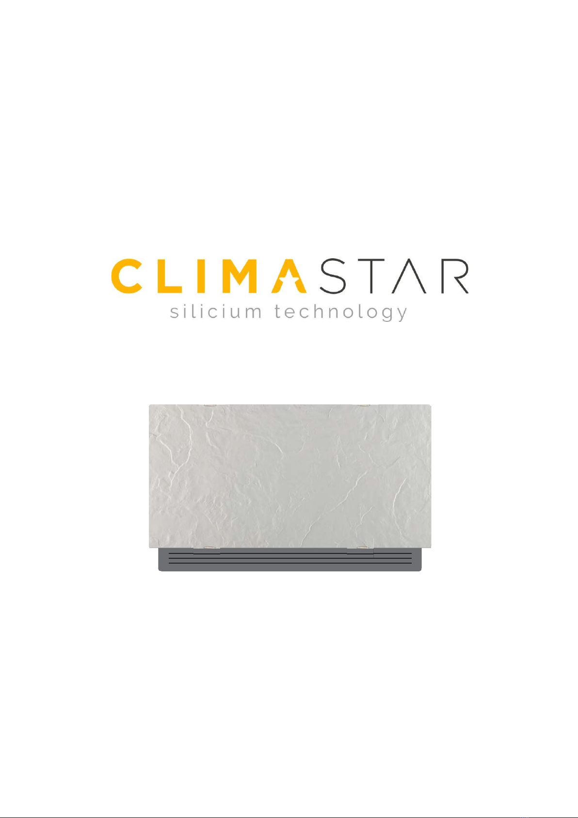
USER’S GUIDE
SILICIUM HYBRID INVERTER


Congratulations on your purchase of your SILICIUM HYBRID INVERTER UNIT!!
The product you have just purchased has undergone numerous tests and inspections to guarantee the
highest quality.
We hope it will give you entire satisfaction.
We are sure you will be happy with it because it represents the state of the art in the technology of home
air conditioning.
By following the suggestions contained in this manual, the air conditioning unit that you have purchased
will operate without problems giving you optimum room temperatures with minimum energy costs.
CLIMASTAR
1. !EUROPEAN DIRECTIVES:
This unit complies with European directives:
• Low tension directive 2006/95/CE
• Electro-magnetic compatibility 2004/108/CE.
• 2002/95/EC Restriction of Hazardous Substances in electrical and electronic equipment (RoHS).
• 2002/96/EC Waste Electrical and Electronic Equipment (WEEE).
• 2002/31/EC labeling showing the energy consumption of air conditioners for household use
2. WALL COMMAND PANEL
The control panel has function memory, so all the settings are not lost in case of switch off or in the event of
power failure.
Eventual anomalies of the single connected terminals are not indicated by the wall panel.
Thanks to the temperature probe, it guarantees anti- freeze safety, even when in stand-by.
After a period of 20 seconds from the last action, the panel light dims and the display shows the environment
temperature. Maximum luminosity is restored when pressing any key.
display
Keyboard
2.1 Display
The display also shows status and eventual alarms through the 8 specific symbols:
2.2 Keyboard
The various functions are set with the 8 backlit keys
2.3 General switch on
-
To manage the device through the control panel, it must be connected to the mains.
-In case of a general switch on the mains supply line, it
must be switched on.
-Switch on the system with the main switch.
2.4 Activation
To activate the device
A
Active cooling
Silent function selected
Maximum ventilation speed selected
Night function selected
Active heating
Alarm signal
OFF
Heating element (blinking light)
heating element activated (fixed light)
Automatic function selected
+
-
Auto
Makes ventilation speed adjustment completely automatic
between a minimum and maximum value.
Silent : allows to limit the ventilation speed to a more contained maximum
value
Temp + allows to increase set temperature
Night function : ventilation speed is limited to a very contained value, and the
set temperature is automatically changed.
Temp - allows to decrease set temperature
Max: allows to set the maximum ventilation speed.
Heating / Cooling : allows to switch operation mode between
heating and cooling.
ON/Stand-By: Allows to activate the device or to put it in standby.
KEY DISPLAY
The display lights up
Auto Auto
Press ON standby.
OPERATION
Select one of the 4 operation modes by pressing the relative key

2.5 Heating / cooling operation mode setting
Flashing of one of the 2 symbols indicates that the water temperature (hot or cold) is not satisfactory, and
the ventilator is stopped until the temperature does not reach an adequate value to satisfy the request.
If the water temperature does not reach a suitable
value for the requested operation, after 10
minutes, the command is blocked, the E5 alarm indicator symbol appears. Unlocking occurs
automatically after 45 minutes, or manually by pressing one of the 8 keys.
2.6
Stand By
When the command is in this operation mode, it guarantees anti-freeze safety. In case the environment
temperature should drop below 5 °C, the hot water solenoid valve and boiler consent outputs are
activated.
2.7
Temperature selection
KEY
OPERATION
DISPLAY
+ / -
Set the desired temperature value, shown on the 3 digits of the display, with the
aid of the two increase and decrease keys.
The adjustment range goes from 16 to 28 °C, with 0.5°C resolution, but over range values of 5°C and
40°C are also consented.
KEY DISPLAY
When heating, the symbol is switched on when the set point is
higher than the environment temperature; they are both switched
off when the set point is lower.
When cooling, the symbol is switched on when the set point is
lower than the environment temperature; they are both switched off
when the set point is higher.
OPERATION
Keep Heating / Cooling pressed down for about 2 seconds to switch
the operation mode between heating and cooling, shown through
the 2 active heating or active cooling symbols which appear.
KEY DISPLAY
OFF
OPERATION
Keep the ON standby key pressed for about 2 seconds. The lack of any light
indicators from the display indicates "standby" status (no function).

2.8 Automatic function
KEY
OPERATION
DISPLAY
Keep the AUTO key pressed. Activation of the function is indicated by the relative
symbol appearing on the display.
Ventilation speed adjustment will occur automatically between a minimum and a maximum value,
according to the effective distance of the environment temperature from the set point, based on a PI type
algorithm.
2.9 Silent function
Key
Operation
Display
Keep the Silent key pressed. Activation of the function is indicated by the relative symbol
appearing on the display.
The ventilation speed is restricted to a more contained maximum value.
2.10 Night function
Key
Operation
Display
Keep the Night operation key pressed. Activation of the function is indicated by the
relative symbol appearing on the display.
By selection this operation mode, the ventilation speed is limited to a very contained value, and the set
temperature is automatically changed as follows:
-
decreased by 1 °C after one hour and an additional degree after 2 hours in heating function;
-
increased by 1 °C after one hour and an additional degree after 2 hours in cooling function.
2.11 ON/ OFF heating elements
Key
Operation
Display
Keep the ON
standby
key
pressed
for about 2
seconds.
The lack of any light
indicators
from the display indicates
"standby"
status (no
function).
The display is OFF
Keep the Night operation key pressed. Activation of the function is indicated by the
relative symbol appearing on the display.
+
Keep the key + pressed to activate the heating elements
-
Keep the key - pressed to disable the heating elements
The display is OFF
3. MAINTENANCE
Periodic maintenance is essential to keep Hybrid INV always efficient, and safe over time. These operations can
be carried out every six months or annually by the Technical Assistance Service, who is technically qualified and
prepared and has the necessary original spare parts.

3.1 Cleaning the outside
-
Before every cleaning and maintenance intervention, disconnect the appliance from the mains by
switching off the master switch.
-
Wait until the parts have cooled down to avoid the risk of burns.
-
Do not use abrasive sponges or abrasive or corrosive detergents
to avoid damaging the painted surfaces.
-
When necessary, clean the outer surfaces of the Air Leaf cooler-
convector with a soft cloth damp cloth.
3.2 Cleaning air suction filter
After a period of continuous operation and in consideration of the concentration of impurities in the air, or
when he intends to restart the plant after a period of inactivity, proceed as described:
-
Extract the front grill by lifting it slightly and turn it until it comes right out of its seat;
-
Extract the filter, pulling it horizontally outwards.
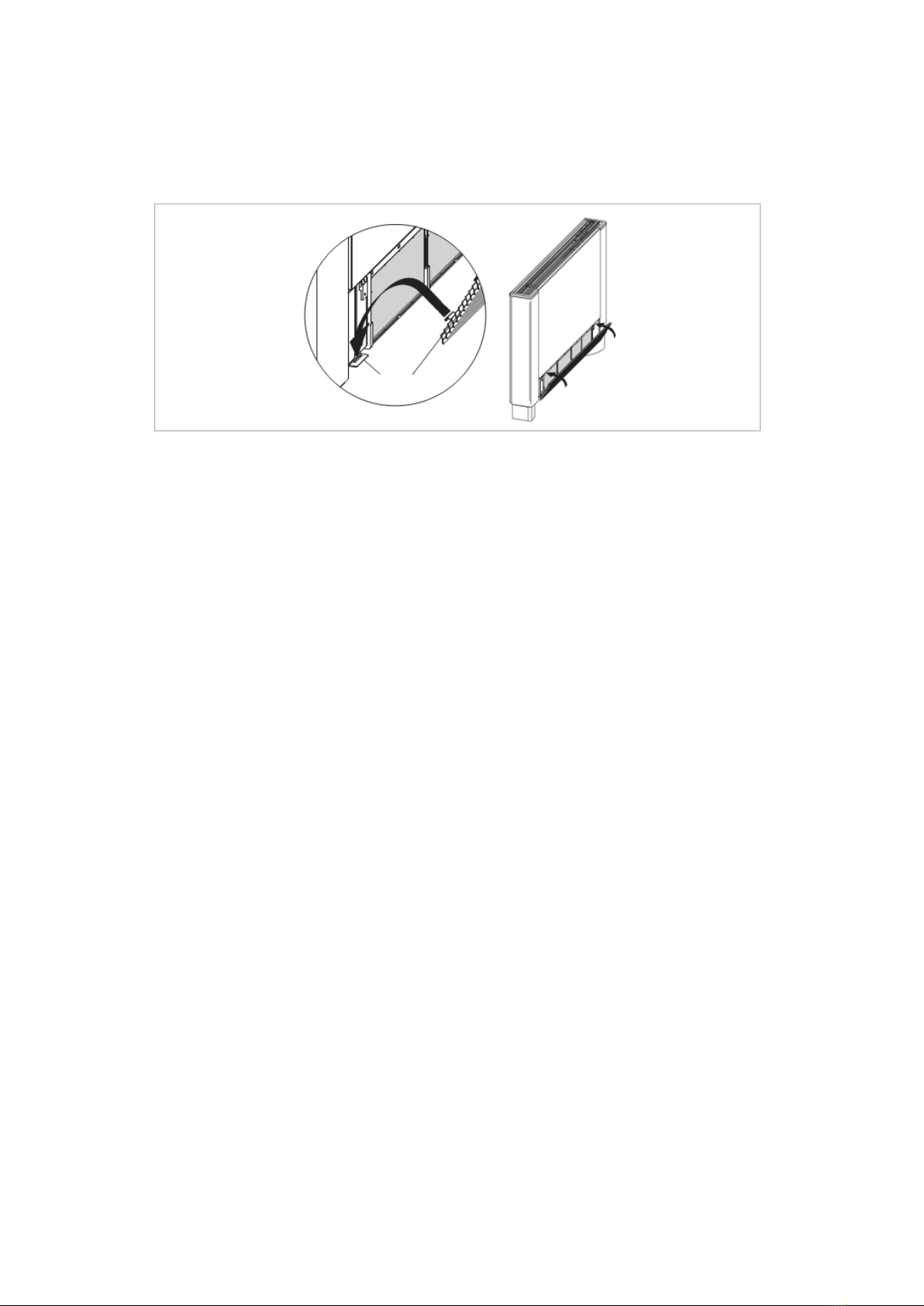
-
It is forbidden to use the unit without the net filters.
-
The appliance is fitted with a safety switch that prevents the operation of the cooler with the mobile
panel missing or out of position.
-
After finishing the cleaning of the filter, check that the panel is mounted correctly.
Insert the two lugs into the special slots, turn it and hook it up with a slight tap on the upper part.
Always keep the filters clean;
- when far possible, keep the doors and windows closed in the room being conditioned;
- limit where possible the effect of direct sun rays in the rooms being conditioned (use curtains, shutters
etc.)
4. Troubleshooting
4.1 Troubleshooting
In case of water leaks or anomalous functioning immediately cut off the power supply and close the water taps.
Should one of the following anomalies occur, contact an authorized service centre or an authorized qualified person,
but do not intervene personally
- The ventilation does not activate even if there is hot or cold water in the hydraulic circuit.
- The appliance leaks water during the heating function.
- The appliance leaks water only during the cooling function.
- The appliance makes an excessive noise.
- There are formations of dew on the front panel.

4.2 Table of anomalies and remedies
The interventions must be carried out by a qualified installer or by a specialized service centre.
Effect
Cause
Remedy
A delayed activation of the
ventilation respect to the new
temperature or function
settings.
The circuit valve needs some time to open
and as a result the hot or cold water takes
time to circulate in the appliance.
Wait for 2 or 3 minutes to open the circuit
valve.
The appliance does not
activate the ventilation.
No hot or cold water in the system.
Check that the water boiler or cooler are
functioning correctly.
The ventilation does not
activate even if there is hot or
cold water in the hydraulic
circuit.
The hydraulic valve remains closed.
Dismount the valve body and check if the
water circulation is restored.
Check the working efficiency of the valve by
powering it separately with 230V. If it
activates the problem could be the electronic
control.
The fan motor is blocked or burnt out.
Check the windings of the motor and thefree
rotation of the fan.
The micro-switch that stops the ventilation
when the filter grill is opened does not
close correctly.
Check that by closing the grill the micro-
switch contact is activated.
The electrical connections are not correct.
Check the electrical connections.
The appliance leaks water
during the heating function.
Leaks in the hydraulic connections of the
system.
Check the leak and fully tighten the
connections.
Leaks in the valve unit.
Check the state of the gaskets.
There are formations of dew on
the front panel.
Thermal insulation unstuck.
Check the correct positioning of the
thermo-acoustic insulation paying attention to
that in the front above the finned battery.
There are drops of water on the
air outlet grill.
In situations of high humidity (>60%)
condensation could form, especially at the
minimum ventilation speeds.
As soon as the humidity starts falling the
phenomenon disappears. In any case the
presence of a few drops of water in the
appliance does not indicate a malfunction.
The appliance leaks water only
during the cooling function.
The condensation bowl is blocked.
Slowly pour a bottle of water in the low part of
the battery to check the drainage; if necessary,
clean the bowl and/or increase the inclination
of the drainage pipe.
The condensation discharge does not
need an inclination for correct drainage.
The connection pipes and the valve unit
are not insulated well.
Check the insulation of the pipes.
The appliance makes a strange
noise.
The fan touches the structure.
Check the clogging of filters and clean them if
necessary
The fan is unbalanced.
The unbalancing causes excessive
vibrations of the machine; replace the fan.
Check the clogging of filters and clean
them if necessary
Clean the filters

5. GUARANTEE
CLIMASTAR guarantees that in the moment of its purchase the product is free of any defect in the materials and in
the work force (limited guarantee). CLIMASTAR offers a commercial and voluntary guaran- tee; conditions
included are similar to those of the legal guarantee, being CLIMASTAR responsible for the non-conformities arisen
in the terms and conditions mentioned below. Moreover, CLIMASTAR offers a total warranty of 2 years in the
spare parts.
- CLIMASTAR is responsible for the non-conformities arisen within the 6 months following the date of sale. If the
non-conformity arises after those 6 months, the user shall prove that the non-conformity already existed when
delivered. The user must inform CLIMASTAR of said non-conformity in a period inferior to two months.
- To obtain the service under the terms of this warranty it is important to detail the device’s purchasing date
because the warranty period starts with the purchase invoice of the system customer. However, in no case this
warranty will be liable for defects that may arise after thirty-six months from the manufacture date.
- This warranty is strictly limited to the repairing in the factory of the manufacturing defect part or parts of the
device, or to the complete replacement of the system when, in the opinion of the manufacturer, it is not possible
or is uneconomical. This does not include any other type of expenditure as an installation, assembly, disassembly
or transport.
- This warranty does not cover defects and / or malfunction caused by accidents, misuse, negligence, wears,
breakage, an incorrect installation and poor electricity supply to the system. This warranty is also excluded if it
is used with another purpose other than heating, for an alteration, modification, tampering or unauthorized
repairing of the product, and by other different causes beyond the manufacturer’s reach after the delivery of the
product.
- The warranty does not cover the costs and expenses incurred to access the device or installation, such as in hidden
locations, heights, non-practicable ceilings. Neither does it include the costs derived from removing or replacing
any structural element to access the device or the installation.
- No heating system will be returned to CLIMASTAR without a previous codified and official MERCHANDISE
RETURN AUTHORITATION. CLIMASTAR assumes no liability for any equipment that is returned without the
previously mentioned MERCHANDISE RETURN AUTHORIZATION.
- CLIMASTAR and/or its agents have the right to decide whether to replace the system or to repair the damaged
components. None of these options will extend the original warranty period.
- Any reparation must be done by the Technical Service and authorized by the manufacturer and/ or any of its
agents; any manipulation done by unauthorized personal will void this warranty. In case of substitution of the
device the buyer must go to the selling centre which will be in charge of receiving the system.
- RESPONSIBILITY LIMITATION: CLIMASTAR as a manufacturer is not responsible for any personal or material
damage that directly or indirectly might result of a non-proper installation, from an improper handling or neither
for the lack of technical qualified staff, nor for the installation costs which are expressly excluded from this
warranty.
- None of the present conditions may be extended or modified without the express consent of CLIMASTAR.

CLIMASTAR GLOBAL COMPANY S.L.
Carretera AS-266 OVIEDO-PORCEYO/ Km.7 Pruvia
33192 - Llanera (Asturias)- SPAIN
Tel: +34 985 66 80 80 / Fax: +34 985 264 751
www.climastar.es
HYBRID INVERTER User Rev. 270120
Table of contents


