Innova Air Compact 4M User manual

INSTRUCTION MANUAL
Via I Maggio, 8
38089 STORO (TN) Italia
Tel. +39 0465 670104
Web site: www.innovaenergie.com
eMail: [email protected]
WATER TO AIR SELF -CONTAINED UNITS
DC INVERTER Technology
Air Compact 4M
Air Compact 6M
Rev 11

Instruction manual
Pag. 2 of 28
Date 2021-07-27
INDEX
1.0 INTRODUC TION ................................................................................................................................................................3
2.0 PACK AGING AND IDENTIFIC ATION .............................................................................................................................4
3.0 UNIT DESCRIPTION ...........................................................................................................................................................5
4.1.1
SAFETY MEASURES……………………………………………………………………………………………………………7
4.1.2
PROHIBITIONS………………………………………………………………………………………………………………..7
4.1.3
RESPONSIBILITY………………………………………………………………………………………………………………8
5.0 INSTALLATION...................................................................................................................................................................8
5.1.1
HYDRAULIC CONNECTIONS…………………………………………………………………………………………….10
5.1.2
AIR D UCTS CONNECTION…………………………………………………………………………………………………13
5.1.3
ELECTRICAL CONNECTION……………………………………………………………………………………………... 16
5.1.4
THERMOSTAT BULBS………………………………………………………………………………………………………..17
6.0 OPERATING............................................................................................................................................................ 18
6.1.1 ALARMS and troubleshooting .................................................................................................................................19
7. 0 WORKING LIMITS .........................................................................................................................................................21
8.0 LIMITED WARRANTY ............................................................................................................................................. 21
9.0 CONTROL PANEL MANUAL ................................................................................................................................ 22

Instruction manual
Pag. 3 of 28
Date 2021-07-27
We would like first of all to thank you for deciding to grant your preference to our product.
By implementing the suggestions that are contained in this manual, thanks to the product that you have
purchased, you can enjoy high thermal comfort with a great energy saving.
Document is confidential by law and may not be copied or transferred to any third party without the
express permission of the manufacturer. The manufacturer reserves the right to make changes at any
time to their models, without prejudice to the essential features described in this manual.
1.0 INTRODUCTION
This manual has been prepared with the aim to give you all the explanations to be able to properly install
the unit SELF-CONTAINED Air Compact and to better manage the device. Improper installation procedures
can result in unsatisfactory performance and / or premature failure of this air conditioning unit. We invite
you to read it carefully before operating the product. If there are any statements or procedures described
in this manual, that you do not understand, contact INNOVA for assistance:
Phone:
+39 0465 670104
E-mail:
info@innovaenergie.com
Keep the manual in a dry location to prevent deterioration, for at least 10 years for any future reference.
In the interest of product improvement, specifications and design of the Air Compact unit will be subject
to change without giving notice.
NOTE: This unit complies with European directives for EMC 2004/108 / CE.

Instruction manual
Pag. 4 of 28
Date 2021-07-27
2.0 PACKAGING AND IDENTIFICATION
The packaging is made of suitable materials to protect the machine from the stress of transport and
handling.
All units are delivered complete and
in perfect condition, however, to
control the quality of transport
services, check the following:
Upon receipt check if the box
is damaged, if that is the case,
accept the goods with reservations
and keep photographic evidence of
any damage found.
Unpack and check the
presence of the individual
components.
Check that all components
have not been damaged during
transport.
WARNING! Lift the unit avoiding to catch it in sensitive parts such as tubing and air adapters.
When the load is lifted off the ground stay away from below and surrounding area.
During transport operations respect the symbols on package e and avoid to place in a vertical position the
product. In fact, the refrigerator compressor is mounted on vibration dampers, and there may be a shift of
the compressor or piping connecting outside their seats. All Aircon Unit are equipped with a pair of lifting
handles, during handling and installation of the unit the lifting handles must be used in order to avoid
possible damages to the gas piping circuit. Any damage to the gas piping circuit due to a wrong handling
of the unit will not be covered by INNOVA Warranty.
Each product is identified by a label as below:

Instruction manual
Pag. 5 of 28
Date 2021-07-27
3.0 UNIT DESCRIPTION
Brushless DC Inverter Technology
This technology is applied to control the speed of the compressor allowing continuous adjustment of the
temperature, in contrast to traditional air conditioning systems where the temperature is controlled by a
compressor that can run only at full speed or complete stop.
The system is equipped with a "Brushless DC" variable speed compressor and relative inverter regulator able
to change and control the motor speed.
The elimination of intermittent (ON / OFF) cycles allows to increase considerably the energy efficiency, the
lifespan of components and increasing the on-board comfort without temperature and relative humidity
fluctuations.
By using unit INVERTER "Brushless DC” it is possible install on board a smaller power generator than the one
necessary for operating a traditional ON/OFF air conditioning.
Energy Saving (40-50% reduction in electrical demand)
As the air temperature approaches the set point value, the inverter control regulates the capacity by
varying smoothly the compressor frequency in order to maintain stable thermal conditions. Thanks to the
variable speed operation and the use of "Brushless DC" motor the efficiency is much higher than ON -OFF
systems, which must continuously stop and start to maintain the temperature.
In terms of seasonal energy efficiency there is a reduction in electricity consumption by 40-50% compared to
traditional air conditioning systems.
The following diagrams give an idea of the operation logic (PID) of this variable speed system.

Instruction manual
Pag. 6 of 28
Date 2021-07-27
Progressive start (no current peaks)
The starting ramp begins at very low frequency (20 Hz) allowing to eliminate peak current at start -up.
Powerful operation
The compressor accelerates to up to 100 HZ (max cooling/heating capacity) after the starting phase, in
order to reach very quickly the room temperature set point.
Comfort
The INVERTER air conditioner continuously adjusts the compressor capacity, adapting to changes in the
thermal load, and it allows to keep the air temperature stable, always near the Set Point value, w ithout
sharp fluctuations.
Thanks to the "Brushless DC " motor and to the sound-absorbing insulation silence is guaranteed during
operation.
ECO mode (depending on fan speed selected)
The air conditioner INVERTER can vary its capacity during operation, while the traditional system can only
operate with a fixed capacity. By selecting the minimum fan speed, the compressor will automatically
switch to low frequency (40 Hz) thus reducing considerably the electrical power consumption. That can be
useful for the energy balance in case other electrical appliances are being used simultaneously.

Instruction manual
Pag. 7 of 28
Date 2021-07-27
4.0 GENERAL NOTICES
4.1.1
SAFETY MEASURES
This instruction manual is an integral part of the appliance and therefore must be kept with care and must
ALWAYS accompany the appliance even in case of its sale to another owner or user or to a transfer to
another plant. In case it is damaged or lost, request another copy from the Technical Service of the area.
During all operations on the device it is necessary to observe the precautions specified in this manual and
on the labels attached to the appliance, as well as all the precautions suggested by common sense, and
the safety regulations currents at the place of installation.
Please read this manual carefully before proceeding with any operation (installation, maintenance, use)
and follow scrupulously the instructions contained in the individual chapters. Failing to comply with the
instructions contained in this manual and use the appliance outside the operating limits specified will void
the warranty.
Make known these instructions to all staff interested at the machine.
The manufacturer assumes no responsibility for damage to people or property arising from the failure to
compliance with the rules contained in this booklet.
In case of replacement of parts, use only original spare parts.
You should always use personal protective elements to perform actions on the devices.
The installation and maintenance of air conditioning equipment may be dangerous because within these
devices there are pressurized refrigerant gas and electrical devices. Therefore the installation, initial start -up
and subsequent maintenance must be carried out by authorized and qualified personnel only.
In case of leakage of refrigerant fluid, it is mandatory to ventilate the room, considering also that refrigerant
fluid when exposed to flame produces toxic gas.
When refilling the system, after eventual leakage and repair, be sure that inside the refrigerant circuit does
not enter any substance, such as air, other than the specified refrigerant (R410A). The presence of air or
other foreign substances in the circuit of refrigerant may cause an abnormal increase of pressure or
breakage, resulting in personal injury.
In the case of water spills from seawater circuit, switch off immediately compressor and source-side pump
and shut off Manual Valves in order to stop the flow.
If the unit is not in use during cold weather, drain all hydraulic circuits connected to the unit, as well as the seawater
condenser, to prevent freezing.
Some parts of the appliance produce heat during operation. The room installation must ensure adequate
ventilation and proper heat dissipation.
4.1.2
PROHIBITION S
We remember that the use of products that use electricity and water involves the observance of some
basic safety rules such as:
It is forbidden the use by children and unassisted disabled people.
Do not touch the appliance when barefoot or with wet or damp parts of the body.
Instruction manual
Pag. 8 of 28
Date 2021-07-27
It is prohibited any operation before disconnecting the unit from the mains supply by moving the
power switch to "off".
Do not modify safety devices or adjustment without permission and instructions from the
manufacturer.
Do not pull, detach or twist the electrical cables coming from the appliance, even if it is
disconnected from the mains power supply.
It is forbidden to open the access panels to the internal parts of the unit without having first
disconnected the unit from the mains by putting the system power switch to "OFF position".
Do not dispose, abandon or leave within the reach of children the packaging material because it
can be a potential source of danger.
It is forbidden to use refrigerant and water pipes for grounding the unit.
It is forbidden to disperse R-410A into atmosphere: R410A is a fluorinated greenhouse gas, referred to
in the Kyoto’s Protocol, with a Global Warming Potential (GWP) = 2088.
4.1.3
RESPONSIBILITY
INNOVA S.r.l. disclaims any liability for damage to people, animals or property resulting from the installation,
use or maintenance improper of the product, or due to failure of compliance with standards and directives
mentioned in this manual.
5.0 INSTALLATION

Instruction manual
Pag. 9 of 28
Date 2021-07-27
Selection and installation of components are left to the responsibility of the installer who must operate
according to the rules of good technique and the legislation in force.
Before connecting the pipes make sure that these do not contain stones, sand, rust, scale or other foreign
objects that could cause damage or failure to the system.
To achieve a successful installation and optimum operating performance, carefully follow the instructions
provided in this manual.
The failure to apply the rules indicated, which may cause malfunction of the appliance, raise the
manufacturer from any form of guarantee and liability for damage caused to people, animals or things.
WARNING! The appliance must be installed in a protected area and in such a way that the accessibility to
the unit is possible only by removing the protection by means of a tool.
WARNING! The appliance must be installed in such a way as to facilitate maintenance.
To further increase the comfort, a sound absorption plate is delivered together with the unit. This part could
be useful only in heating mode to eliminate the high frequency noise coming from the expansion of
refrigerant fluid through the source-side water evaporator. However if the unit is located inside a closed
space, the plate is useless and it can be easily removed before installation.

Instruction manual
Pag. 10 of 28
Date 2021-07-27
5.1.1
HYDRAUL IC CONNECTIONS
The following is a summary of how to install the unit on a source circuit and at the outlet:
CORRECT SYSTEM INSTALLATION
The minimum nominal diameter of the connecting pipes should be 1".
WRONG SYSTEM INSTALLATION EXAMPLES:

Instruction manual
Pag. 11 of 28
Date 2021-07-27
SOURCE CIRCUIT
Installing electric-pump
The source-side pump is needed to circulate the amount of water required in the heat exchanger. If
necessary, the system can also work in a closed circuit, for example with a geothermal system.

Instruction manual
Pag. 12 of 28
Date 2021-07-27
IMPORTANT!
It is required a filter between the water intake and electric-pump, in order to protect it from any foreign
matter. Failure to install filter void the warranty of the pump and the unit.
Self- contained installation
Connect the self-contained heat exchanger
unit in the following manner:
NOTE: to allow the maintenance or repair
operations it is essential that each hydraulic
connection is provided with the respective
shut off valve.
DRAIN
5.1.2
AIR DUCTS CONNECTION
IMPORTANT! Both outlet fittings can be ducted allowing the highest air flow rate, however in case of
restricted space for installation, only one outlet can be ducted while the other shall be closed.
For Air Compact 6M at least two outlets must be used.
The diameter of the ducts should not be less than the diameter of the outlet nozzles.
SELF CONTAINED
AIR COMPACT 4M
ducts diameter 125mm
SELF CONTAINED
AIR COMPACT 6M
ducts diameter 150mm

Instruction manual
Pag. 13 of 28
Date 2021-07-27
Air Compact 4M: 125 => 150 mm flange substitution
The Air Compact 4M can work at its maximum performance with one duct only using the size 150mm, to do
that the horizontal 125 mm flange must be dismounted and substituted with the 150mm flange supplied with
the unit. The top outlet can be closed with the supplied 120mm stopper.
In case of use with a 125 mm duct only, the unit has a 10% performance loss.

Instruction manual
Pag. 14 of 28
Date 2021-07-27
Suction
The ambient air is sucked through one or more grids of appropriate size. The grid dimensions should respect
the suction area of the unit.
Air distribution
The system needs a correct air flow in order to work efficiently. It is therefore important to get the correct
distribution without bottlenecks, by maintaining the original nozzle diameter and not exceeding the
recommended length of pipes.
The air ducts should be insulated type and must be well stretched to allow a good air flow.

Instruction manual
Pag. 15 of 28
Date 2021-07-27
AIR FILTER
The air conditioner sucks air from the environment through an air-gas exchanger equipped with aluminum
fins having small pitch. A filter must be located upstream the exchanger in order to protect it from dust.
NOTE: the filter must be easy reachable to be extracted for the normal operations of cleaning and / or
replacement whenever required.

Instruction manual
Pag. 16 of 28
Date 2021-07-27
5.1.3
ELECTRICAL CONNECTION
Warning
It is important that the electrical system is done according to the rules, respecting the data provided in
chapter Technical data and it shall be properly grounded.
FIXING
The electrical box is delivered fixed on the self-contained unit, however in case of limited space during
installation it can be detached (by 3 screws) and fixed elsewhere at a max distance of 0.6 m. It must be
installed inside a space provided with suitable ventilation.

Instruction manual
Pag. 17 of 28
Date 2021-07-27
5.1.4
THERMOSTAT BUL BS
A temperature sensor bulb is fixed to the drain pan through a bracket and located near the unit air suction.
The main temperature sensor working sensor is located inside the room thermostat,

Instruction manual
Pag. 18 of 28
Date 2021-07-27
ON/OFF
►
Il
6.0 OPERATING
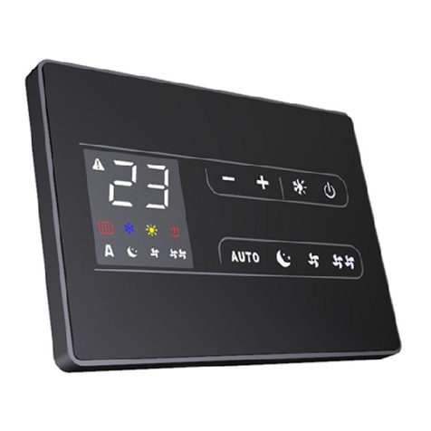
From remote controller it is possible to select the On/Off mode, the cooling, heating mode, to change the set point
temperature (+ / -), to select the fan speed (min., med., max., auto).
The room thermostat must be installed in a proper position, away from direct heat source. The set point temperature
and real value are shown on the thermostat display.
display
.
6
a
liu
c
n
=
1
o
.
.
,
{fi,
"•
i
=
i
a .,'lr e'
f},
*,
)Jl',_
c,J,,-
Il
'
The room thermostat has to be connected with the PCB through the 5 m cable ( supplied with the unit).
For the user interface display operation please read carefully the specific instructions attached
Control Panel PIN Out (environment thermostat)

Instruction manual
Pag. 19 of 28
Date 2021-07-27

Instruction manual
Pag. 20 of 28
Date 2021-07-27
6.1.1 ALARMS and troubleshooting
In case of failure the following codes are shown on two digits display in the electrical box:
E1
:
Room temperature: sensor failure;
E2
:
Evaporator coil temperature: sensor failure;
E3
:
Seawater inlet temperature: sensor failure;
E4
:
Condenser temperature: sensor failure;
E5
:
Indoor DC Fan failure;
E7: Communication error between main MCU and room thermostat;
LP: Low Pressure switch alarm; HP: High Pressure switch alarm;
LT: low evaporator temperature in heating mode
In case of alarm from E1 to E7 please try to switch OFF the unit and then ON again, if the problem persists call a
INNOVA authorized service.
The HP alarm in cooling mode could be due to a clogged source circuit, or the pump not working properly (e.g.
thermal load protection). Please visually check the overboard drain, and in case of poor water flow, check and clean
all parts involved.
In case of HP alarm appears in heating mode, the air flow through the air outlet could be too low. Please check all the
ducts are not obstructed somewhere. Also, the air suction filter, if dirty, could cause high pressure, provide then to
clean it before restarting the unit.
LP alarm is most commonly due to a consistent leakage of refrigerant, check the refrigerating circuit for leakages.
In case of LT alarm, the problem may be due to poor water circulation on the source side or too low water
temperature (below 5°C). Please check the seawater flow first as specified above.
7.0
WORKING LIMITS
The unit operates correctly within the following ranges:
✓
Summer cooling mode: 15°C < source-side temperature< 40°C
✓
Winter heating mode: 10°C < source-side temperature < 20°C
Should working conditions be out of these ranges, in your particular application, please contact INNOVA
before installation in order to find a suitable solution.
7.1 Recommendations for sources with sea, lake or river water
Localized situations: in some regions, it is common to experience a tremendous presence of jellyfish or
seaweed concentrated in back bay marinas for some periods of time. This can clog strainers, water pumps
and heat exchangers in a little while, causing shut-down faults and sometimes equipment damage. In such
particular conditions, please seek for the advice of a local INNOVA service representative. Any possible
modification to the overall system (self-contained, pumps, strainers, etc.) that could overtake the problem
must be approved by INNOVA, otherwise warranty coverage will expire.
The standard pump is not self-priming: any damage incurred due to a pump running dry is not covered
under warranty. Air conditioning system must be switched off, as well as pumps, whenever there is a risk of
pump loosing priming, due to particular seawater conditions related to the boat type and its speed. The
compressor could be damaged if the seawater flow through the heat exchanger is considerably reduced.
This manual suits for next models
1
Table of contents
Other Innova Inverter manuals

Innova
Innova AirLeaf ECA644 User manual

Innova
Innova AirLeaf ECB649 User manual

Innova
Innova AirLeaf ECA644 User manual

Innova
Innova 2.0 User manual

Innova
Innova Air Leaf ECA644 User manual

Innova
Innova 10 HP DC User manual

Innova
Innova EB0644 User manual

Innova
Innova Filomuro SLW 400 User manual

Innova
Innova SL User manual

Innova
Innova 2.0 15HP User guide
Popular Inverter manuals by other brands

Sumitomo
Sumitomo HF-520 Series manual

Berges
Berges ACM-D2 Series operating manual

Toshiba
Toshiba Tosvert-130 installation manual

PAW
PAW SolarBloC midi Basic DN 20 Installation and commissioning instructions

Resol
Resol DeltaSol AL E Manual for the specialised craftsman

Toshiba
Toshiba TOSVERT VF-AS3 manual