Clinton Electronics Pro CE-DVR400 User manual
800-549-6393
800-633-8712

Clinton Pro Series DVR
WARNING
RISK OF ELECTRIC SHOCK
DO NOT OPEN
WARNING: TO REDUCE THE RISK OF ELECTRIC SHOCK,
DO NOT REMOVE COVER (OR BACK).
NO USER-SERVICEABLE PARTS INSIDE.
REFER SERVICING TO QUALIFIED
SERVICE PERSONNEL.
The lightning flash with arrowhead symbol, within an equilateral triangle, is intended to alert the user to the presen e of
uninsulated “dangerous voltage” within the produ t’s en losure that may be of suffi ient magnitude to onstitute a risk of
ele tri sho k.
The ex lamation point within an equilateral triangle is intended to alert the user to the presen e of important operating and
Maintenan e (servi ing) instru tions in the literature a ompanying the applian e.
C MPLIANCE N TICE F FCC:
THIS EQUIPMENT HAS BEEN TESTED AND FOUND TO COMPLY WITH THE LIMITS FOR A CLASS A DIGITAL
DEVICE, PURSUANT TO PART 15 OF THE FCC RULES. THESE LIMITS ARE DESIGNED TO PROVIDE
REASONABLE PROTECTION AGAINST HARMFUL INTERFERENCE WHEN THE EQUIPMENT IS OPERATED IN
A COMMERCIAL ENVIRONMENT. THIS EQUIPMENT GENERATES, USES, AND CAN RADIATE RADIO
FREQUENCY ENERGEY AND IF NOT INSTALLED AND USED IN ACCORDANCE WITH THE INSTRUCTION
MANUAL, MAY CAUSE HARMFUL INTERFERENCE TO RADIO COMMUNICATIONS. OPERATION OF THIS
EQUIPMENT IN A RESIDENTIAL AREA IS LIKELY TO CAUSE HARMFUL INTERFERENCE, IN WHICH CASE
USERS WILL BE REQUIRED TO CORRECT THE INTERFERENCE AT THEIR OWN EXPENSE.
CAUTI N: CHANGES OR MODIFICATIONS NOT EXPRESSLY APPROVED BY THE PARTY RESPONSIBLE
FOR COMPLIANCE COULD VOID THE USER’S AUTHORITY TO OPERATE THE EQUIPMENT.
THIS CLASS OF DIGITAL APPARATUS MEETS ALL REQUIREMENTS OF THE CANADIAN INTERFERENCE-
CAUSING EQUIPMENT REGULATIONS.
The information in this manual is believed to be a urate as of the date of publi ation. The information
ontained herein is subje t to hange without noti e. Revisions or new editions to this publi ation may be
issued to in orporate su h hanges.

Important Safeguards
1. Read Instru tions
All the safety and operating instru tions should be read before the
applian e is operated.
2. Retain Instru tions
The safety and operating instru tions should be retained for future
referen e.
3. Cleaning
Unplug this equipment from the wall outlet before leaning it. Do not
Use liquid aerosol leaners. Use a damp soft loth for leaning.
4. Atta hments
Never add any atta hments and/or equipment without the approval of
The manufa turer as su h additions may result in the risk of fire,
ele tri sho k or other personal injury.
5. Water and/or Moisture
Do not use this equipment near water or in onta t with water.
6. A essories
Do not pla e this equipment on an unstable art, stand or table. The
equipment may fall, ausing serious injury to a hild or adult, and
serious damage to the equipment. Wall or shelf mounting should
follow the manufa turer’s instru tions, and should use a mounting kit
approved by the manufa turer.
7. Power Sour es
This equipment should be operated only from the type of power sour e
Indi ated on the marking label. If you are not sure of the type of power,
please onsult your equipment dealer or lo al power ompany.
8. Power Cords
Operator or installer must remove power and TNT onne tions before
handling the equipment.
9. Lightning
For added prote tion for this equipment during a lightning storm, or
when it is left unattended and unused for long periods of time, unplug it
from the wall outlet and dis onne t the antenna or able system. This
will prevent damage to the equipment due to lightning and power-line
surges.
10. Overloading
Do not overload wall outlets and extension ords as this an result in
the risk of fire or ele tri sho k.
11. Obje ts and Liquids
Never push obje ts of any kind through openings of this equipment as
They may tou h dangerous voltage points or short out parts that ould
Result in a fire or ele tri sho k. Never spill liquid of any kind on the
Equipment.
12. Servi ing
Do not attempt to servi e this equipment yourself. Refer all servi ing
to qualified servi e personnel.
13. Damage requiring Servi e
Unplug this equipment from the wall outlet and refer servi ing to
qualified servi e personnel under the following onditions:
A. When the power-supply ord or the plug has been damaged.
B. If liquid is spilled, or obje ts have fallen into the equipment.
C. If the equipment has been exposed to rain or water.
D. If the equipment does not operate normally by following the
operating instru tions, adjust only those ontrols that are overed by
the operating instru tions as an improper adjustment of other
ontrols may result in damage and will often require extensive work
by a qualified te hni ian to restore the equipment to its normal
operation.
E. If the equipment has been dropped, or the abinet damaged.
F. When the equipment exhibits a distin t hange in performan e —
this indi ates a need for servi e.
14. Repla ement Parts
When repla ement parts are required, be sure the servi e te hni ian has
used repla ement parts spe ified by the manufa turer or that have the
same hara teristi s as the original part. Unauthorized substitutions
may result in fire, ele tri sho k or other hazards.
15. Safety Che k
Upon ompletion of any servi e or repairs to this equipment, ask the
servi e te hni ian to perform safety he ks to determine that the
equipment is in proper operating ondition.
16. Field Installation
This installation should be made by a qualified servi e person and
should onform to all lo al odes.
17. Corre t Batteries
Warning: Risk of explosion if battery is repla ed by an in orre t type.
Dispose of used batteries a ording to the instru tions.
18. Tmra
A manufa turer’s maximum re ommended ambient temperature
(Tmra) for the equipment must be spe ified so that the ustomer and
installer may determine a suitable maximum operating environment
for the equipment.
19. Elevated Operating Ambient Temperature
If installed in a losed or multi-unit ra k assembly, the operating
ambient temperature of the ra k environment may be greater than room
ambient. Therefore, onsideration should be given to installing the
equipment in an environment ompatible with the manufa turer’s
maximum rated ambient temperature (Tmra).
20. Redu ed Air Flow
Installation of the equipment in the ra k should be su h that the amount
of airflow required for safe operation of the equipment is not
ompromised.
21. Me hani al Loading
Mounting of the equipment in the ra k should be su h that a hazardous
ondition is not aused by uneven me hani al loading.
22. Cir uit Overloading
Consideration should be given to onne tion of the equipment to
supply ir uit and the effe t that overloading of ir uits might have on
over urrent prote tion and supply wiring. Appropriate onsideration
of equipment nameplate ratings should be used when addressing this
on ern.
23. Reliable Grounding
Reliable grounding of ra k mounted equipment should be maintained.
Parti ular attention should be given to supply onne tions other than
dire t onne tions to the bran h ir uit (e.g., use of power strips).

Table of Contents
Chapter 1 Basi Install Page 7
1.1 Conne ting the Video Sour e
1.2 Conne ting the Monitor
1.3 Conne ting the Mouse
1.4 Conne ting the Network Port
1.5 Conne ting the Power
Chapter 2 Programming the DVR Page 9
2.1 Pro Series Tool Bar
2.2 Logging into the system
2.3 The Menu Tab
2.3.1 System Setup I on
2.3.1.2 General Setup
2.3.1.3 Alarm Type Setup
2.3.1.4 Hard Drive Setup
2.3.1.5 Password Setup
2.3.1.6 Configuration Saving
2.3.1.7 Shutdown
2.3.2 Camera Setup I on
2.3.2.2 Camera Setup
2.3.2.3 Adjusting Pi ture Quality
2.3.2.4 PTZ Setup
2.3.2.5 Spot Monitor Setup
2.3.2.6 Sequential Swit hing
2.3.2.7 Monitor Setup
2.3.3 Network Setup
2.3.3.2 Ethernet Setup
2.3.3.3 Remote Client Setup
2.3.3.4 Email Setup
Chapter 3 Re ording Video Page 32
3.1 Re ording S hedule
3.2 Time Re ording
3.2.1 Programming All The Cameras at on e
3.2.2 Programming Individual Cameras

Table of Contents (Cont.)
3.3 Event Programming
3.3.1 Programming All the Cameras at on e
3.3.2 Programming ameras individually
3.3.3 Programming the Motion Fields
3.4 Che king the DVR Status
Chapter 4 Wat hing Live Video Page 41
4.1 Camera Change Sub-Menu
4.2 PTZ Control
Chapter 5 Playing Ba k Re orded Video Page 45
5.1 Sear hing Video
5.1.1 Time and Date Sear h
5.1.2 Event Sear h
5.2 Playba k Controls
5.3 Multi-S reen Hot Button
Chapter 6 Ar hiving Video Page 49
6.1 Ba kup
6.2 Cut and Save
6.3 Playing ba k ar hived video on your PC
Chapter 7 Advan ed Installation Page 52
7.1 Conne ting Audio
7.2 Conne ting Alarms
7.3 Conne ting the RS485
7.4 Conne ting the PTZ
Appendix – Troubleshooting Page 55
Appendix – Spe ifi ations Page 56
Clinton Pro Series DVR
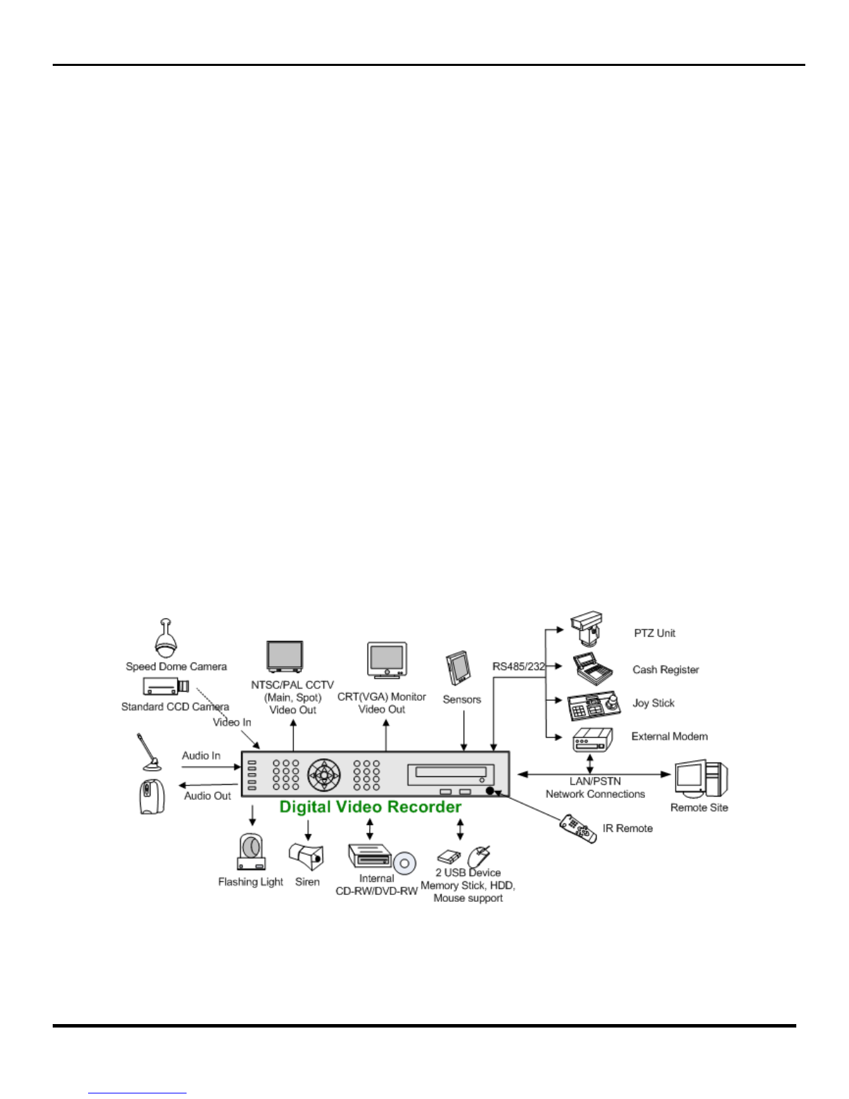
Introduction
Features
The Clinton Pro Series digital video re order (DVR) provides re ording apabilities for four, eight or 16
amera inputs. It provides ex eptional pi ture quality in both live and playba k modes, and offers the
following features:
• 4, 8 or 16 Composite Input Conne tors
• Compatible with Color (NTSC or PAL) and B&W (CCIR and EIA-170) Video Sour es
• Multiple Sear h Engines (Date/Time, Calendar, Event)
• Re ords up to 240 NTSC Frames per Se ond (200 PAL Frames per Se ond)
• “Loop-Through” Video Conne tors
• Continuous Re ording in Disk Overwrite Mode
• Continues Re ording while Ar hiving, Transmitting to Remote Site and during Playba k
• User-friendly Graphi al User Interfa e (GUI) Menu System
• Various Re ording Modes ( Manual / S hedule / Event)
• Audio Re ording and Playba k
• Alarm Conne tions In lude: Input, Output.
• Built-in Alarm Buzzer
• Live or Re orded Video A ess via Ethernet.
3
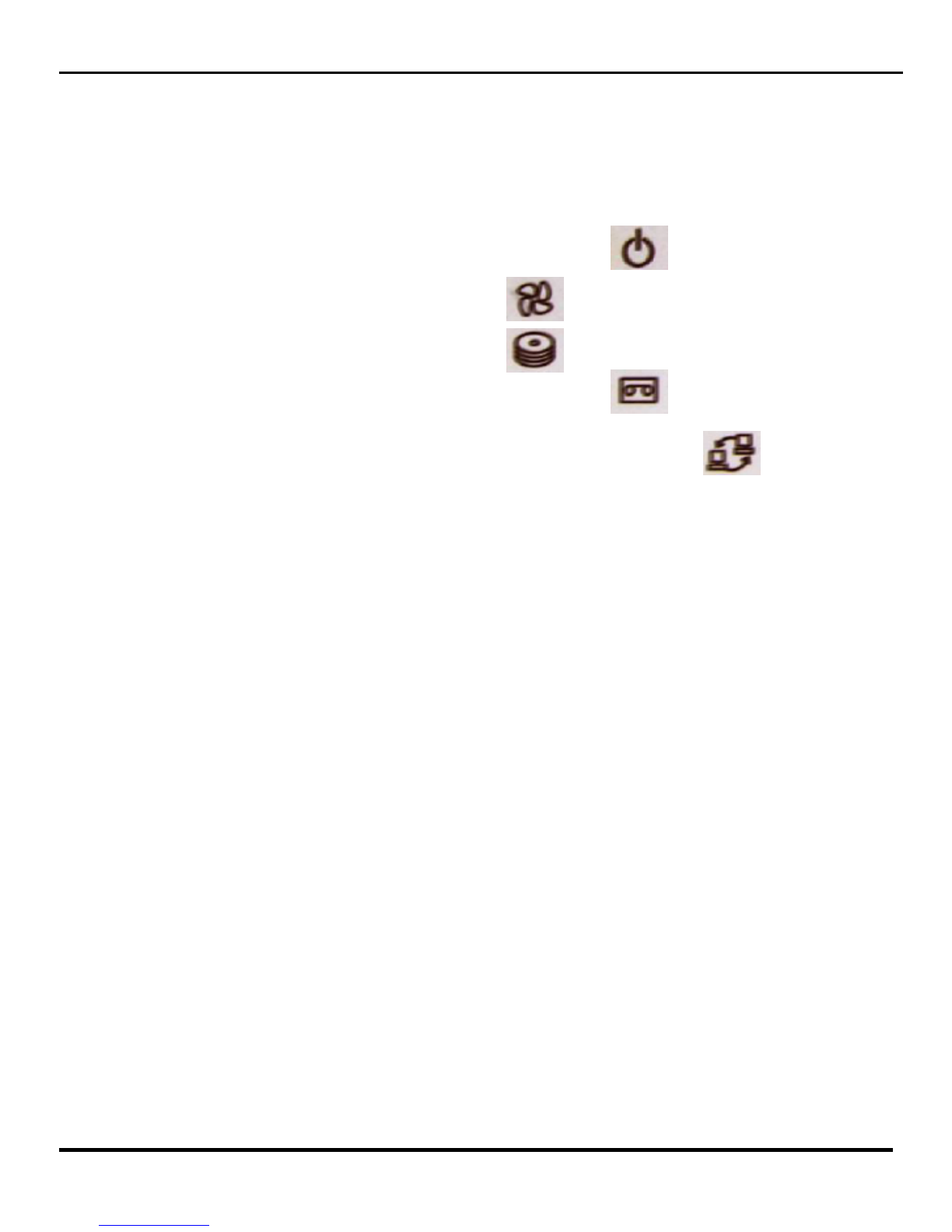
Front Panel Description
The front panel of the Pro Series DVR features two USB Ports, The CDRW, and Five LED
ndicators which are explained below.
Power Led is lit when power is provided to the DVR Unit.
Fan Led is lit when the cooling fan is running.
The CDRW Led is lit when the CDRW is in use.
The Record Led is lit when the DVR unit is recording.
The Network LED is let when the DVR unit is connected to a network.
4
Clinton Pro Series DVR
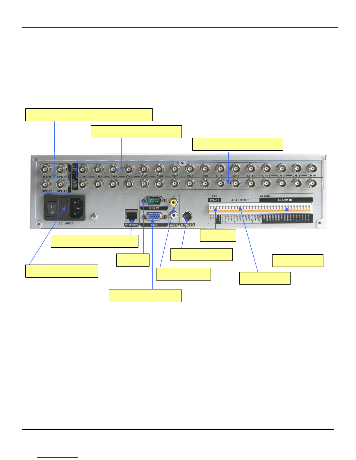
Rear Panel Layout
CAMERA INPUT (1~16)
LOOP OUT (1~16)
MONITOR OUTPUT (MAIN / SPOTS)
AC POWER INPUT
RJ45 ETHERNET PORT
RS232
VGA MONITOR OUT
S-VIDEO OUT
AUDIO IN/OUT
RS485
ALARM OUT
ALARM IN
5
Clinton Pro Series DVR

IR Remote Controller
Number
Lo k (Log out)
Fast Rewind /
PTZ
Fast Forward
/ Play
▲ Arrow /
Panorama
Menu
Sear h
Ba kup
Rotate
Pause
Display
Es ape
ID REC
◀ Arrow ▼ Arrow / Smart
Zoom
Fo us
Iris
Preset
Enter
6
Clinton Pro Series DVR
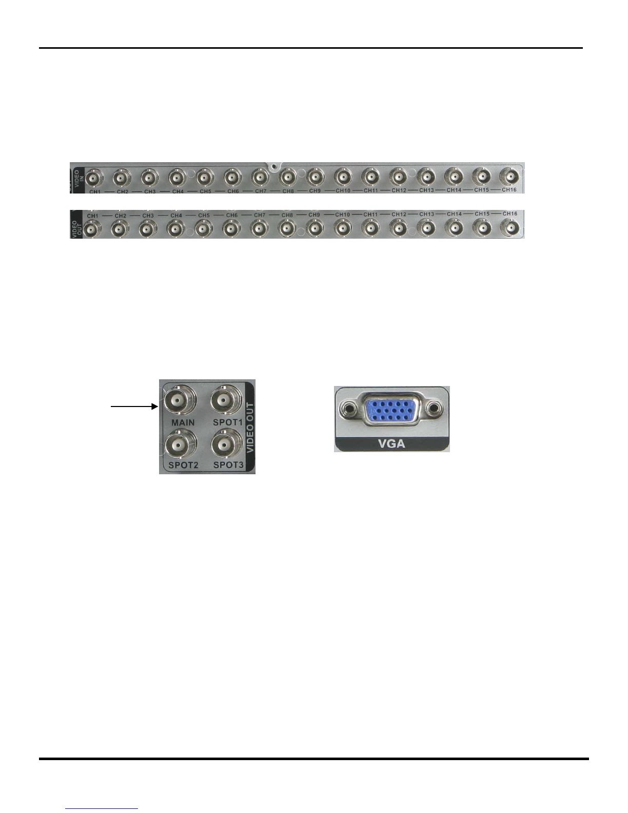
1.1 Connecting the Video Source
Connect the coaxial cables from the video sources to the BNC Video In (Top Row) connectors.
If ou would like to connect our video source to another device, ou can use the Loop BNC
connectors (Bottom Row).
N TE: The Loop BNC connectors are auto terminated. Do N T connect a cable to the Loop BNC
unless it is connected to another terminated device because it will cause poor quality video.
1.2 Connecting the Monitor
Connect the monitor to either the Main BNC Connection or the VGA connection located on the
back panel of the DVR Unit.
1.3 Connecting the Mouse
Connect the mouse to the first (left) USB slot located on the DVR’s front panel.
NOTE: The Pro Series DVR will work with either the enclosed R Remote or the Mouse.
Clinton Pro Series DVR
Chapter 1 – Basi Installation (Physi al Conne tions)
Main
7

1.4 Connecting to the Network Port
The DVR can be networked using the 10/100Mb Ethernet connector. Connect a Cat5 cable with
an RJ-45 jack (Standard Ethernet Cable) to the DVR connector. The DVR can be networked
with a computer for remote monitoring, searching, configuration and software upgrades. See
Chapter 4 — Configuration for configuring the Ethernet connections.
1.5 Connecting the Power
Attach the supplied power cord into the back of the DVR unit, then connect the other end of the
cord into an electrical outlet to suppl the DVR with power.
Once all of the ph sical connections have been made, our DVR will be initialized and it will
take approximatel 60 seconds. As soon as the DVR completes its initialization process, it will
begin showing live video on the attached monitor (assuming power has been applied to the
connected cameras). The default mode will displa all cameras at once.
Once the Initialization process has finished the DVR is read for programming.
NET
Clinton Pro Series DVR
8

Clinton Pro Series DVR
Chapter 2 — Programming the DVR
2.1 The Pro Series Tool Bar
The Pro Series DVR’s main tool bar (pictured below) will appear when ou move the mouse
cursor near the top of the Live Video Screen on the main monitor. All programming, video
searching and archiving features can be accessed through this tool bar.
Tool Bar (Pictured above).
2.2 Logging into the System
Prior to gaining access to an of the Pro Series DVR’s features or functions, ou will need to login
to the DVR. Prior to logging into the DVR, using the mouse, drag the cursor over the menu tab on
the DVR tool bar and left click. The Login Screen will appear on the monitor (below).
Security Level Button Password Button
Using the Mouse, click on the securit level button until it reads ADMIN. During initial setup the
Password Button should read root. Then click on the numbers listed below to enter the Passcode.
The Default Pass code is 1111. Then click on OK and ou will be logged into the DVR.
Keep in mind, there are three levels of securit for the Pro Series DVR, Admin, Superuser and
User. Onl users logged-in under the Admin securit level are allowed to make programming
changes to the DVR. We highl recommend safeguarding the default Password and entering our
own passwords and passcodes under the appropriate securit levels. See Section 2.3.1.5 for more
information on setting passwords.
9

Clinton Pro Series DVR
2.3 The Menu Tab
All initial programming is done through the menu tab on the DVR Toolbar. Click on the Menu Tab
and the Setup Menu (Pictured Below) will appear. There are five submenus available through the
Setup Menu. Click on each icon to access each submenu. The icons (from left to right below) are 1.
The System Setup Icon, 2. Camera Setup Icon, 3. Recording Setup Icon, 4. Network Setup Icon, .
System Information Icon.
The Setup Menu
10
Clinton Pro Series DVR
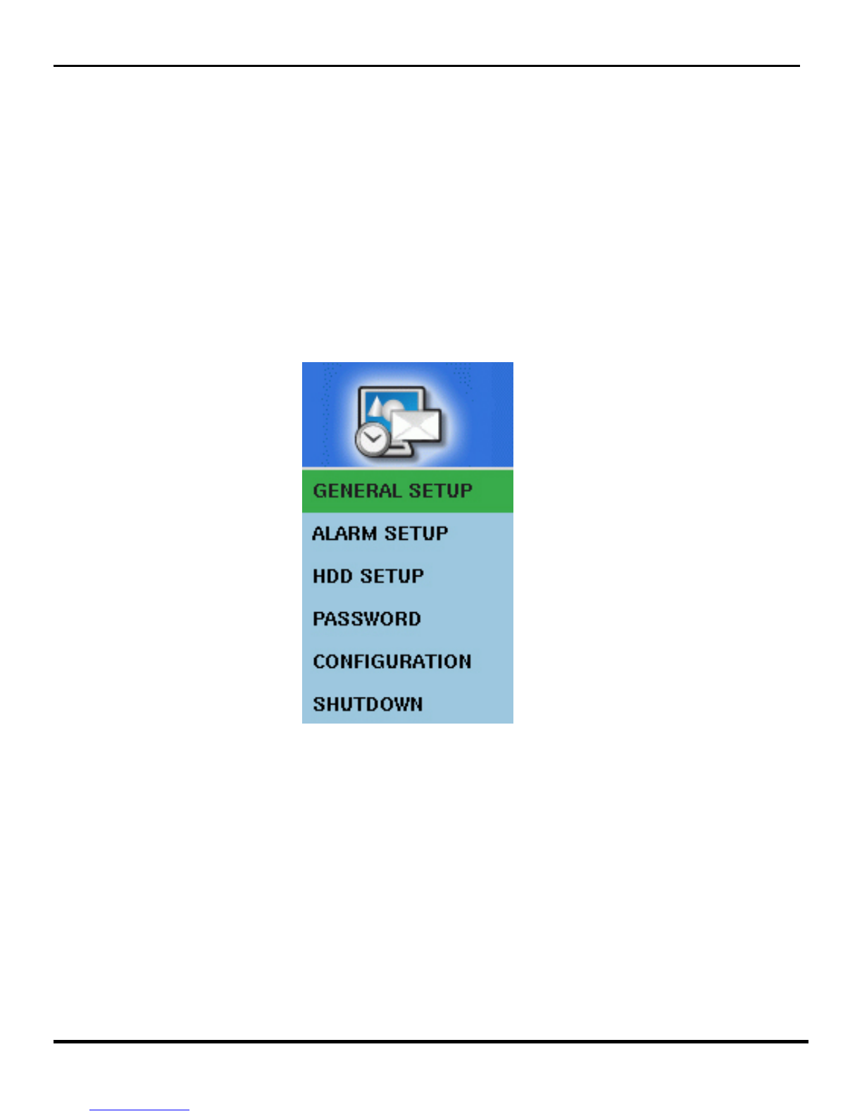
2.3.1 The System Setup Icon
By li king on the System Setup I on lo ated in the main menu a drop down box (Pi tured Below) will
appear on the monitor. The submenu’s listed under this i on will allow you to do the basi system
programming for the Pro Series DVR.
11

2.3.1.2 General Setup
Cli k the General Setup listing and the General Setup Sub-Menu will appear.
VIDEO FORMAT: For North American operation should be NTSC or AUTO.
LANGUAGE: Is defaulted to English.
DATE FORMAT: Allows ou to change the wa the date will appear on the monitor.
TIMEZONE: Clicking on the Time zone categor will open a dropdown box where ou can
choose between several DST (Da light Savings Time) locations or choose to not use the DST
function at all. If ou choose DST OFF, the DVR will need to be manuall programmed each and
ever time there is a time change.
DATE DISPLAY: When On, the Date will be displa ed in Live View for each camera. When off,
no date will be displa ed in Live View.
DATE: Allows ou to make changes to toda ’s date.
TIME: Allows ou to make changes to the time.
BUZZER: There are several audible warning sounds available on the Pro Series DVR. This is the
main on/off switch for all buzzers. When off is chosen, ou will not be able to select an of the
individual warning buzzers located throughout the programming menus.
UNIT ADDRESS: You can set up an ID for our DVR to distinguish the unit when using
multiple DVR’s.
BASE CAMERA NUMBER: Useful in multiple DVR situations. Default is 1, but ou can assign
an starting point.
MENU TIME OUT: You can set up the menu time-out duration up to 10 minutes.
NOTE: Any changes made in this sub-menu, you must click on the SAVE button located at
the bottom of the General Setup Submenu.
Clinton Pro Series DVR
12

2.3.1.3 ALARM TYPE Setup
Sele t the ALARM TYPE from the System Setup sub-menu and the ALARM TYPE sub-menu will appear.
Drop Down Arrow
Alarm N Alarm OUT
ALARM IN: Click on the Alarm In selection (pictured above) to program the polarit of the alarm
inputs connected to the DVR. Use the Drop Down Box (pictured above) to select NO (Normall
Open) or NC (Normall Closed). The Pro Series DVR has one available alarm input for each
camera on the s stem.
ALARM OUT: Click on the Alarm Out selection (pictured above) to enable or disable each alarm
output connected to the DVR. The Alarm Set Button will activate an connected alarms, the
Alarm Clear Button will clear all triggered alarms. The Pro Series DVR has four alarm outputs, no
matter how man camera inputs each model ma have.
NOTE: Be sure to click on the SAVE button at the bottom of the ALARM TYPE sub-menu to
finalize an changes made in this sub-menu.
2.3.1.4 Hard Drive Setup
All HDD functions are done at the factor . Contact our service representative for more
information.
Clinton Pro Series DVR
13
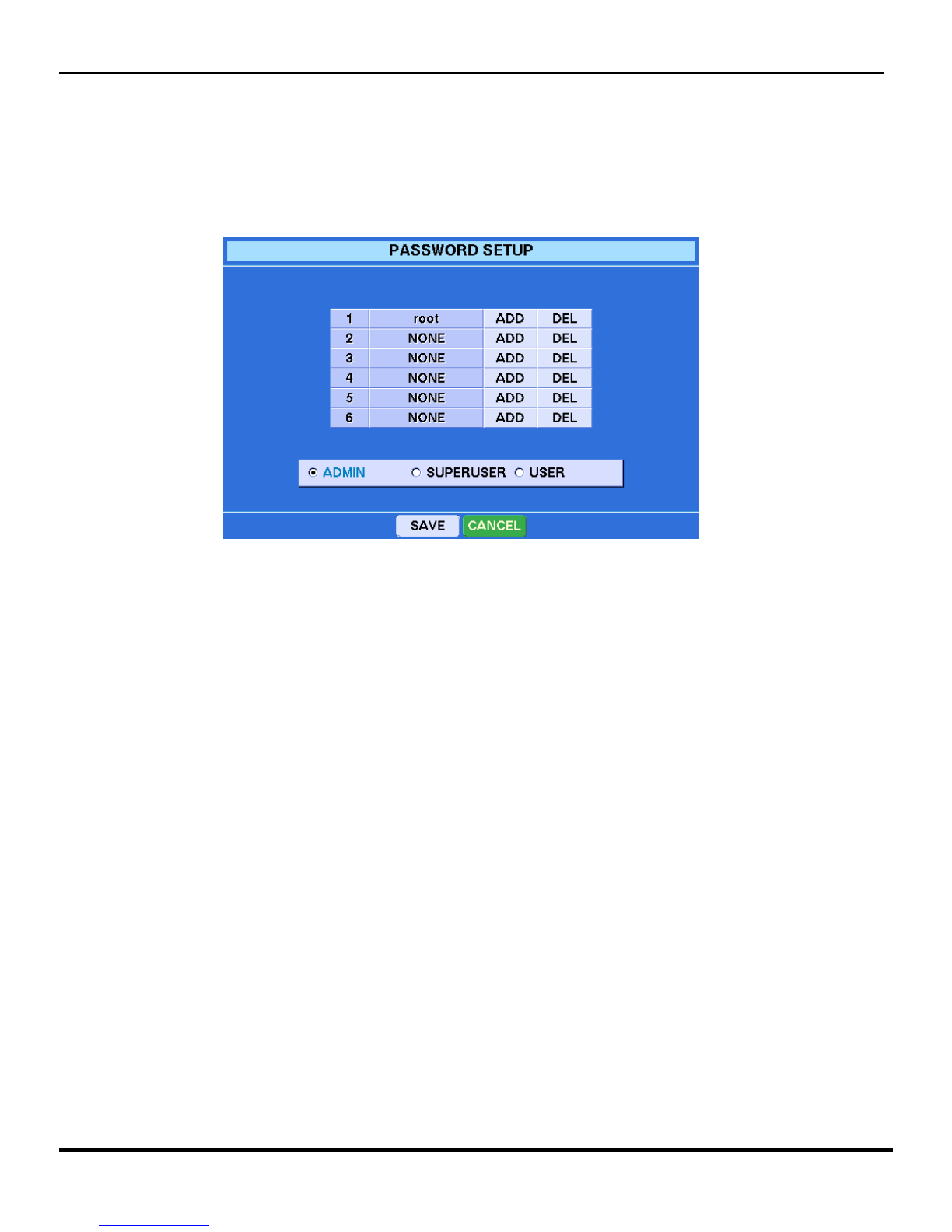
2.3.1.5 PASSW RD SETUP
To add or delete passwords to the head end of the Clinton Pro Series DVR, select the Password
selection from the S stem Setup sub-menu, and the following menu will appear on the monitor.
There are three levels of securit built into the Clinton Pro Series DVR: ADMIN, SUPERUSER
and USER. Passwords can onl b added, deleted or changed b and ADMIN level user.
To ADD a new password, click on the selected securit level ou would like to add and then click
on the ADD button next to an open user spot. An open user spot will sa NONE in the name
column. A ke board will appear on screen. T pe in a user name and then hit the SAVE button on
the ke board. A new menu will appear asking ou for a new password. The new password must be
at least 4 numbers. The DVR will ask ou to confirm the new password, then click the SAVE
Button and our new password will be added.
To DELETE a password, click on the selected securit level and then on the DEL button next to
user ou would like to delete. The s stem will ask ou to confirm our deletion. Click es, then
click SAVE at the bottom of the Password sub-menu.
CAUT ON: Do not delete the default Admin account (root) before adding a new account.
ADM N Level has access to all on board features of the DVR
SUPERUSER Level can access al features except program changes
USER Level can watch live video, use the PTZ functions, and check the DVR status.
Clinton Pro Series DVR
14
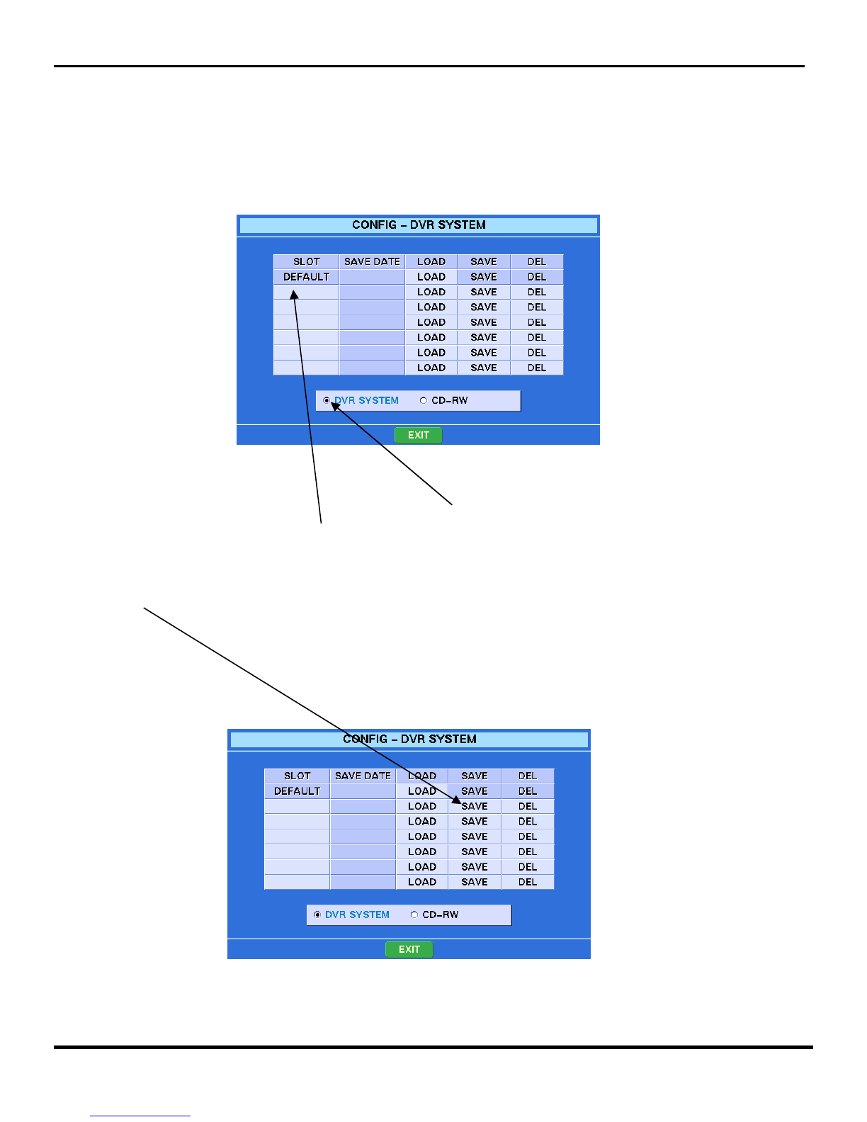
2.3.1.6 C NFIG
You an save onfigurations of the Clinton Pro Series DVR’s programming to the DVR or a CD. This would
be helpful in programming multiple DVR’s with the exa t same programming. Sele t the CONFIG sub-
menu from the System Setup sub-menu and the following s reen will appear.
To Save a onfiguration to the DVR: Cli k on the DVR System button lo ated at the bottom of the menu.
Then li k on a blank box under the SLOT olumn and a virtual keyboard will appear. Give your
onfiguration a name and li k on the keyboard’s SAVE button.
The urrent onfiguration now has a name and is ready to be saved to an ar hiving portion of the hard
drive. Cli k SAVE on the line next to your newly named onfiguration and the onfiguration will be saved.
On e saved, the date will appear next to your onfiguration name.
Now you an make hanges to the programming of your DVR and always revert ba k to any saved
onfiguration.
Clinton Pro Series DVR
15

To LOAD a onfiguration saved on the DVR, sele t the CONFIG submenu from the System Setup
Submenu. Cli k LOAD on any one of the saved onfigurations and the following s reen will appear.
You an now hoose to load the entire onfiguration or, using the mouse pla e a he k next to the items
you want to load and then li k on OK. The DVR will ask you to onfirm your hoi e, li k OK and the
saved onfiguration will be loaded within a few se onds.
SAVE/LOAD CONFIGURATION TO A CD
Sele t the CONFIG submenu from the System Setup submenu and the following will appear on the main
monitor.
Cli k on the CD-RW Button and the CD LOAD/SAVE Menu will appear. (Pi tured on next page)
Clinton Pro Series DVR
16

Make sure the onfiguration you want to save to the CD is the a tive onfiguration on the DVR. Pla e a CD
in the CD drawer of the DVR and li k the SAVE button. Within a few se onds the CD Drawer will reopen
and the onfiguration will be saved to that CD. You an now pla e that CD in any Pro Series DVR and
download the onfiguration.
TO LOAD a saved onfiguration onto a se ond DVR, put the CD with the saved onfiguration in the CD
drawer of the DVR you are attempting to onfigure and li k on the LOAD button of the menu pi tured
above.
Clinton Pro Series DVR
17
Other manuals for Pro CE-DVR400
1
This manual suits for next models
2
Table of contents
Other Clinton Electronics DVR manuals

Clinton Electronics
Clinton Electronics Pro CE-DVR400 User manual

Clinton Electronics
Clinton Electronics Cricket User manual

Clinton Electronics
Clinton Electronics CE-RP5 User manual

Clinton Electronics
Clinton Electronics Shadow Series Instruction manual

Clinton Electronics
Clinton Electronics CE-RP2 User manual

Clinton Electronics
Clinton Electronics Contender CE-DVR4 User manual

Clinton Electronics
Clinton Electronics PRO SERIES User manual

Clinton Electronics
Clinton Electronics CE-HDVR4 User manual

Clinton Electronics
Clinton Electronics Shadow Pro User manual

Clinton Electronics
Clinton Electronics RP1 User manual


