Clinton 8890BH User manual

ML8890BH-7
CLINTON
MODEL 8890BH
PROGRAMMABLE CONTROLLER
DRIVE SYSTEM
FOR
DURKOPP 558
BUTTONHOLE MACHINE
SERVICE MANUAL
Para Español vea el reverso del libro
40-0240-01

SECTION I - DESCRIPTION . . . . . . . . . . . . . . . . . . . . . . . . . . . . . . . . . . . . . . . . 1-1
SECTION II - INSTALLATION . . . . . . . . . . . . . . . . . . . . . . . . . . . . . . . . . . . . . . . . 2-1
A.
B.
C.
D.
E.
F.
G.
DRIVE PULLEY . . . . . . . . . . . . . . . . . . . . . . . . . . . . . . . . . . . .
SYNCHRONIZER & SENSOR . . . . . . . . . . . . . . . . . . . . . . . . . .
SEWING HEAD DRIVE PULLEY . . . . . . . . . . . . . . . . . . . . . . . .
START SWITCH . . . . . . . . . . . . . . . . . . . . . . . . . . . . . . . . . . . .
AIR CYLINDER . . . . . . . . . . . . . . . . . . . . . . . . . . . . . . . . . . . . .
UPPER MOTOR . . . . . . . . . . . . . . . . . . . . . . . . . . . . . . . . . . . .
EMERGENCY STOP SWITCH . . . . . . . . . . . . . . . . . . . . . . . . .
2-1
2-2
2-3
2-4
2-4
2-5
2-5
SECTION III - ADJUSTMENTS INSTRUCTIONS . . . . . . . . . . . . . . . . . . . . . . . . . . 3-1
A.
B.
C.
D.
E.
F.
G.
HOME POSITION . . . . . . . . . . . . . . . . . . . . . . . . . . . . . . . . . . .
FIRST STITCH POSITION . . . . . . . . . . . . . . . . . . . . . . . . . . . .
NEEDLE UP POSITION . . . . . . . . . . . . . . . . . . . . . . . . . . . . .
MOTOR FUNCTION & SENSOR TEST . . . . . . . . . . . . . . . . . .
TENSION RELEASE . . . . . . . . . . . . . . . . . . . . . . . . . . . . . . . . .
SWING KNIFE & LOOPER THREAD TRAPPER . . . . . . . . . . . .
THREAD NIPPER . . . . . . . . . . . . . . . . . . . . . . . . . . . . . . . . . . .
3-1
3-1
3-1
3-2
3-2
3-2
3-3
SECTION IV - MODES OF OPERATION . . . . . . . . . . . . . . . . . . . . . . . . . . . . . . . . . 4-1
A.
B.
C.
D.
FULL CYCLE . . . . . . . . . . . . . . . . . . . . . . . . . . . . . . . . . . . . . . .
SINGLE STEP . . . . . . . . . . . . . . . . . . . . . . . . . . . . . . . . . . . . . .
MOVE TABLE ONLY . . . . . . . . . . . . . . . . . . . . . . . . . . . . . . . . .
REPAIR CYCLE . . . . . . . . . . . . . . . . . . . . . . . . . . . . . . . . . . . . .
4-1
4-2
4-2
4-2
SECTION V - PROGRAMMING MODE . . . . . . . . . . . . . . . . . . . . . . . . . . . . . . . . . . 5-1
A.
B.
C.
D.
HOW TO PROGRAM . . . . . . . . . . . . . . . . . . . . . . . . . . . . . . . .
ACCESS TO HIDDEN PARAMETERS . . . . . . . . . . . . . . . . . . .
MASTER RESET . . . . . . . . . . . . . . . . . . . . . . . . . . . . . . . . . . . .
EXPLANATION OF PARAMETERS . . . . . . . . . . . . . . . . . . . . .
5-1
5-1
5-2
5-2
1.
2.
3.
4.
5.
PARAMETERS WITH DIRECT ACCESS . . . . . . . . . . . . .
TIMERS . . . . . . . . . . . . . . . . . . . . . . . . . . . . . . . . . . . . . . .
COUNTERS . . . . . . . . . . . . . . . . . . . . . . . . . . . . . . . . . . . .
TOGGLE SWITCHES . . . . . . . . . . . . . . . . . . . . . . . . . . . .
HIDDEN PARAMETERS . . . . . . . . . . . . . . . . . . . . . . . . . .
5-2
5-2
5-3
5-3
5-4
E. PARAMETER LIST . . . . . . . . . . . . . . . . . . . . . . . . . . . . . . . . . . 5-6
SECTION VI - TEST MODE . . . . . . . . . . . . . . . . . . . . . . . . . . . . . . . . . . . . . . . . . . . 6-1
A.
B.
C.
D.
E.
F.
G.
H.
BUILT-IN TEST PROGRAM . . . . . . . . . . . . . . . . . . . . . . . . . . .
TESTING THE HOME AND SEW SENSORS . . . . . . . . . . . . .
TESTING THE CLAMP DOWN AND START SWITCHES . . . .
TESTING THE MOTORS . . . . . . . . . . . . . . . . . . . . . . . . . . . . .
EXITING THE TEST MODE . . . . . . . . . . . . . . . . . . . . . . . . . . .
DESCRIPTION OF THE HOME AND SEW SENSOR BLOCKS
USING THE EMERGENCY STOP BUTTON . . . . . . . . . . . . . .
AIR PRESSURE SWITCH . . . . . . . . . . . . . . . . . . . . . . . . . . . . .
6-1
6-1
6-1
6-1
6-2
6-2
6-3
6-3
ML8890BH-8
TABLE OF CONTENTS

ML8890BH-9B
SECTION I
DESCRIPTION
The Clinton Model 8890BH is a Micro Computer Controlled Electro / Mechanized / Pneumatic
system designed to enhance the performance and drastically reduce the maintenance required
to operate a Durkopp Buttonhole machine.
Two DC Servo Motors are used to replace the complete mechanized stop motion components
including the clutch, brake, spur gears and shafts.
State of the art sensors are used to communicate position and speed data to the single micro
computer control system. By use of the LCD Programmable Display, both the machine speed
and buttonhole "Eye" speed can be precisely entered and controlled. The LCD can also be used
to command repair cycles or 3 step cycles to assist in machine maintenance.
Figure 1-1 shows the major components of the system.
FIG. 1-1
1-1
UPPER MOTOR
NEEDLE-UP-
SENSOR
SENSOR
ASSEMBLY
LCDDISPLAY
STOP
SWITCH
START
SWITCH
LCD POST
ASSEMBLY

FIG. 2-2
02-4007-01
COLLAR
10-1457-01
PULLEY ASS'Y
EXISTING
CRANK
FIG. 2-1
ML8890BH-10
2-1
SECTION II
INSTALLATION
Insure that the machine is in working order.
Mark the home position.
A. To install the drive pulley assembly. Remove the manual crank mechanism by rotating the crank
in the clockwise direction (See Fig. 2-1). Remove the pulley carrier assembly by loosening the hex
nut which attaches it to the reversing lever (Fig. 2-1, Item 1) and sliding the entire assembly off the
end of the cross shaft. Remove the large hex nut which holds the manual crank onto the crank hub
(Fig. 2-1, Item 2). Remove all parts from the crank hub. Loosen hex head screw (Fig. 2-1, Item 3)
and slide it toward the operator as far as it will travel in it’s adjusting slot. Place collar (02-4007-01)
and pulley assembly (10-1457-01) on the end of the cross shaft (See Fig. 2-2).
NOTE: The pulley assembly contains a locking bearing, insure that the bearing locks and drives
the shaft in the counterclockwise direction and free-wheels in the clockwise direction. Replace
the crank hub, spring holding device, manual crank and retaining nut (Fig. 2-2).
ROTATE
CLOCKWISE
TO REMOVE
3
1
2

B. To install the synchronizer and sensor assemblies. Remove cover assemblies (Fig. 2-3).
Remove the hand wheel and sewing head pulley by removing the two locking nuts (Fig. 2-4,
Item 1). Remove the stop motion eccentric (Fig. 2-4, Item 2) by removing the threaded stud
(Fig. 2-4, Item 3). Retain thehand wheel, washer and locking nuts so that they may be put back
on at a later time. Remove the stop motion roller assembly (Fig. 2-5, Item 1) by loosening the two
clamp screws (Fig. 2-5 , Item 2). Manually rotate the machine to it’s furthest foreword point (half
way around the eye). Remove the stop motion leaf spring assembly (Fig. 2-5, Item 3) and three
forks lever by loosening the clamp screw (Fig. 2-6, Item 2) and sliding the leaf spring shaft out of
the casting. Remove torsion spring assembly (Fig. 2-6, Item 1). Remove the length adjusting slide,
stop and gauge plate (Fig. 2-7, Items 1, 2, & 3). Remove the tension release block (Fig. 2-7,
Item 4)from the length adjusting slide and attach it to the first stitch sensor block (Fig. 2-8,
10-1458-01). Replace the length adjusting slide with the first stitch sensor block. Using the screw
provided install the home position sensor block (Fig. 2-8, 02-4008-01) and stop bracket (Fig. 2-8,
02-4015-01). Using the screws provided install the sensor block assembly (Fig. 2-8).
WARNING: Insure that there is at least 1/16th of an inch clearance between bottom of
thehome and sew sensors and the home position and first stitch blocks
(Fig. 2-9) so that no damage is caused to the sensors when the machine is
cycled.
FIG. 2-3
FIG. 2-4 1
2
3
RETAIN FOR
REINSTALLATION
ML8890BH-11A
2-2

1
4
2
3
FIG. 2-7 FIG. 2-8
FIG. 2-5 FIG. 2-6
3
1
2
3
2
1
C. To install the sewing head drive pulley assembly. Attach the magnet disk holder to the sewing
head pulley (Fig. 2-8). Slide the pulley onto the arm shaft. Replace the hand wheel, washer and
locking nuts (Fig. 2-4).
ML8890BH-12A
2-3

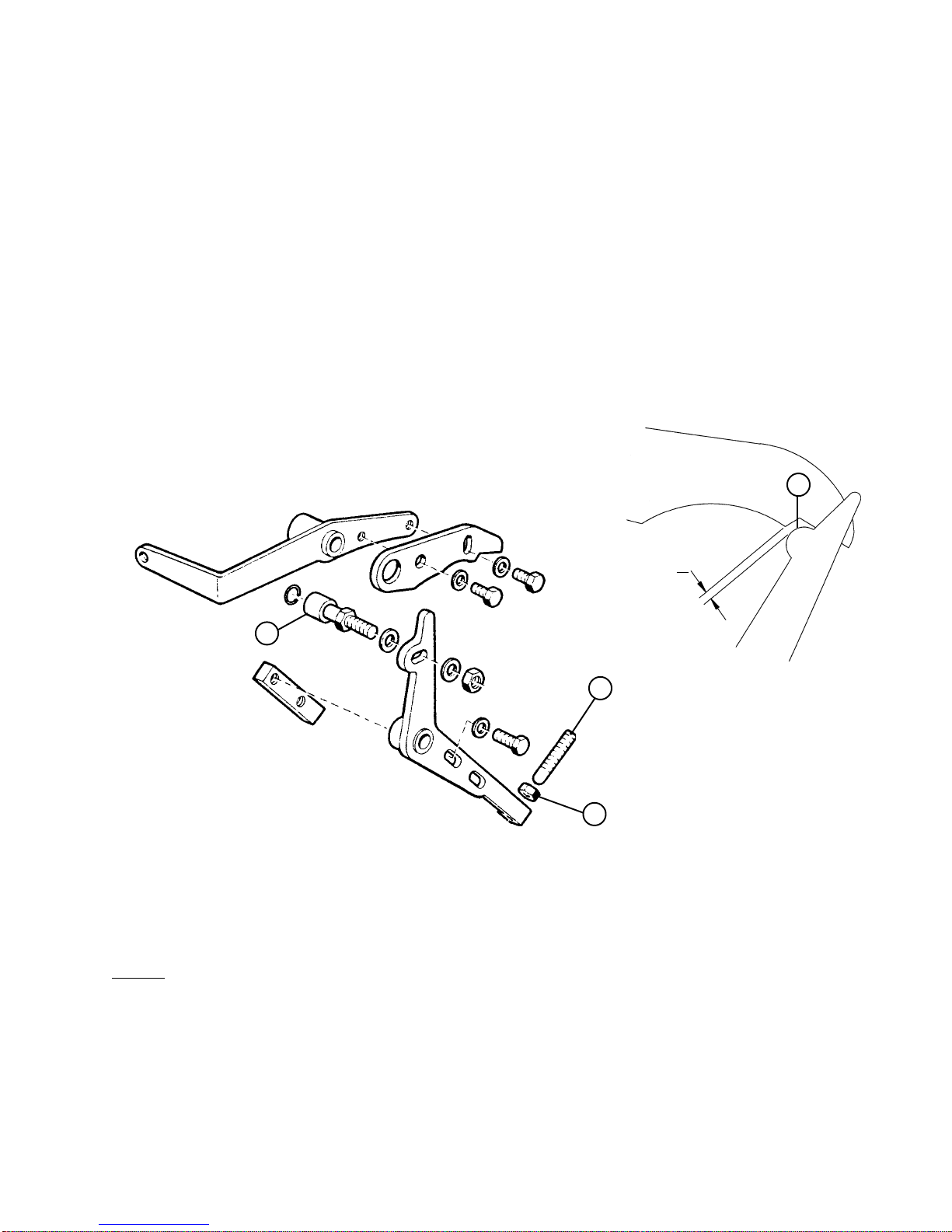
D. To install the start switch assembly. Remove the hand lever and clamping angle
(Fig. 2-9, Item 1 & 2) by removing the two pivot pins (Fig. 2-9, Item 3 & 4). Remove the manual
start switch (Fig. 2-9, Item 5). Remove the stop stud and locking nut (Fig. 2-9, Item 6 & 7).
Remove the clamping lever (Fig. 2-10, Item 1) by removing the lock nut and pivot bolt (Fig. 2-10,
Item 2 & 3). Install the start switch. (See Fig. 2-12).
2
1
3
4
7
6
FIG. 2-9 FIG. 2-10
3
1
2
FIG. 2-11 FIG. 2-12
E. To install the air cylinder assembly. See Fig. 2-12.
2-4
ML8890BH-13A
INS-2594

F. To install the Upper Motor. Remove the two cover retaining screws (Fig. 2-13, Item 1), and using
the screws provided install the upper motor (See Fig. 2-14).
1
FIG. 2-13 FIG. 2-14
G. To install the Emergency Stop Switch. Use the screws provided and install as shown
(See Fig. 2-15). MOUNTING
SCREWS
MOUNTING
SCREW
FIG. 2-15
2-5
ML8890BH-14

ML8890BH-15
SECTION III
ADJUSTMENT INSTRUCTIONS
Removetheneedle.
A. To set the Home Position. Returnthemachinetothehomepositionbyrotatingthe
manualcrankuntilthearrowsonthehomepositionlabelsare aligned. Making sure that
theairsupply is disconnected turn the power on. Loosening thehomepositionblock
retainingscrew(Fig. 2-8) and slide the home position blocktowardtherearofthemachine
asfarasthe adjusting slot will allow. Slowly pull the home position block toward the
operatoruntilthe indicator light on the home position sensorgoesout. Gentlypushthe
homeposition block toward the rearofthemachineuntiltheindicator light again comes on.
Tightentheretainingscrew.
B. Tosetthe first stitch position. Rotatethe machine with themanual crankuntil theleading
edgeofthe material clamp is aligned with the needle. Loosen the first stitch sensor block
retainscrewandpush the stitch sensor block toward therearofthemachine as far as it will
travel. Pullthefirststitchsensorblocktowardtheoperatoruntiltheindicatorlightonthe
firststitchsensorcomeson. Tightenthe retaining screw. Returnthemachinetothehome
position.
C. To set the needle up position. Rotatethe hand wheel until the needle bar is at todead
centerwiththelefthand looper at the extreme left hand end ofit’sstroke. Withthe
machineinthispositionloosenthesetscrewsonthe magnet disk. Rotate the magnet disk
untilthe magnet is aligned with the magnetsensoronthesynchronizerboardandas close
aspossibletoit without touching. Tightenthesetscrews.
Connectthe air supply.
CAUTION: With the air supply now connected the machine will cycle if the start
switch is depressed.
3-1
D. SENSOR and MOTOR FUNCTIONS. To test the sensor and motor functions, with the table motor
and sewing motor drive belts removed test the sensor and motor functions as described on
(page 6-1, B) of the programming manual. This will insure that the sensors and motors are
operating as intended in order to prevent any damage to the sewing head. Replace the drive belts.
E. TENSION RELEASE MECHANISM. Remove the cloth plates and set the machine to the Single
Step mode of operation (See programming instructions page 4-1). Depress the start switch, the
machine will cycle to the first stitch position. Depress the start switch a second time, the
machine will complete the stitching phase of the cycle and stop after the last stitch. With the
machine in this position insure that the tension release roller (Fig. 3-16, Item 1) is 1 mm from the
lobe on the tension release arm (Fig. 3-16, Item 2). If it is not, loosen the locking nut (Fig. 3-16,
Item 3) and set the gap using the adjusting screw (Fig. 3-16, Item 4).
NOTE: For fixed length machines, where the swing knife is actuated from the cam skip to step 9.
F. SWING KNIFE and LOOPER THREAD TRAPPER. With the machine still at the end of the
sewing phase of the cycle, insure that the swing knife actuating block (Fig. 3-17, Item 1) is 1 mm
from the swing knife linkage (Fig. 3-17, Item 2). When this gap has been properly set, depress the
start switch, the machine will move to the punch position phase of the cycle. With the machine in
this position insure that the looper thread trapper (Fig. 3-18, Item 1) is approximately 1 mm to the
right of the slot in the throat plate (Fig. 3-18, Item 2).
FIG. 3-16
4
3
1 mm
1
2
ML8890BH-16
3-2

1 mm
FIG. 3-17 FIG. 3-18
G. To set the Thread Nipper. With the machine still in the punch position, insure that the thread
nipper (Fig. 3-19, Item 1) is completely closed and that the thread can not pull through it.
FIG. 3-19
1
1
2
1
2
Depress the start switch, the machine will cycle to the home position. The machine is now
readyfor operation.
ML8890BH-17
3-3

SECTION IV
PROGRAMMING INSTRUCTION
MODES OF OPERATION
The LCD display may be operated in any one of three different modes.
They are:
OPERATING MODE, PROGRAMMING MODE and TEST MODE.
I OPERATING MODE
There are four different headings contained in this mode, they are:
FULL CYCLE
SINGLE STEP
MOVE TABLE ONLY
REPAIR CYCLE
To change from one operating mode to the next press the button.
Example: If the display reads “FULL CYCLE “ press the button, the display will
now read “SINGLE STEP“. To return to the “FULL CYCLE“ mode continue pressing the
button until the display again reads “FULL CYCLE“.
A. FULL CYCLE
Two different “FULL CYCLE” modes are possible:
“FULL CYCLE 2 STEP” (default selection) or
“FULL CYCLE 1 STEP”
If this mode is selected, the machine starts on the first stage of the START SWITCH, the
second stage has no function. In all the other modes like “SINGLE STEP” , “MOVE TABLE
ONLY” or “REPAIR CYCLE”, the first stage operates the clamp.
In the 2 step mode, the first stage of the START SWITCH is for toggling the clamp.
When operating in this mode the machine is set to sew a complete button hole automatically.
After starting the cycle, by pressing the start button, the table motor moves the table from the
“home position“ to the “sew position“. To adjust the speed see page 5-4 (5a3). At the
sew position, the table motor stops and the sew motor starts.
In the full cycle mode the following options may be selected:
1. SLOW START (1 to 25 of the beginning stitches may be programmed to run at a slower
R.P.M. than the rest of the sewing cycle this helps to insure that the machine will start
sewing on the first stitch and prevents the machine from being knocked out of time if any
mechanical failure should occur. One or two stitches is generally all that is needed).
2. SLOW EYE (This is provided to run the machine at a slower R.P.M. around the eye of
the button hole in order to provide better thread coverage at the eye).
3. SLOW END (1 to 25 of the end stitches may be programmed to run at a slower speed
than the rest of the sewing cycle).
ML8890BH-18
4-1

To overlap the last stitch with the first, an adjustable stitch counter is available (see page 5-3 (3e)).
After finishing the sew mode the table motor starts again and moves the table back to the “home
position“. On the way back to home position the hole will be punched. After punching the hole
the clamp can be raised before the table is at home position to insure that the shear cutter dose
not cut the material. To adjust the raise timing of the clamps see page 5-4 (5b2).
B. SINGLE STEP
This mode provides step-by-step operation of the machine for easy adjustment and
maintenance. To operate:
Press the START switch: The table moves to the sew position.
Press the START switch again: The button hole will be sewn.
Press the START switch again: The table moves back to home position.
C. MOVE TABLE ONLY
In this mode the table moves only from home position to home position without sewing.
This mode is used for adjusting the button slot knife.
D. REPAIR CYCLE
After pressing the START switch the table moves to the sew position and stops, if the switch is
fully released. Then if the START switch is depressed to it’s first position (dropping the clamp
in the normal operation mode) the table will move at a very slow speed to any point around the
button hole. When the table has been jogged to the desired position the sewing cycle may be
started by fully depressing the START switch.
ML8890BH-19
4-2

ML8890BH-20
SECTION V
PROGRAMMING MODE
There are two ways to go from the operating to the programming mode. Press the button
to go to the first group (SPEEDS). Continue pressing this key to step through the
groups or press the button to go to the last changed parameter.
After changing the parameters press the button to return to the operating mode.
A. HOW TO PROGRAM
1. SPEEDS, TIMERS, COUNTERS
Select the parameter group with the button to the desired parameter
group (example SPEEDS).
Select the desired parameter ( example SOFTSTART ) by pressing the button.
Change displayed number with ( increase ) or ( decrease ) button.
2. TOGGLE SWITCHES
Select the parameter group “TOGGLE SWITCHES“ with the button.
Select the desired parameter to be changed with the button.
Toggle the desired parameter with the or button.
B. ACCESS TO HIDDEN PARAMETERS
Step 1: Turn power off.
Step 2: Press the and buttons at the same
time.
Step 3: Turn power on while both buttons are pressed.
Step 4: Release the buttons.
The display shows stars (*****) which are counting down.
Step 5: Press the button before the stars disappear.
Step 6: Select the desired parameter as usual.
The hidden parameters have stars in front of the group name
Normal parameter: SPEEDS
Hidden parameter: **** SPEEDS
Note: Access to HIDDEN PARAMETERS is disabled after power is shut off.
5-1

ML8890BH-21
C. MASTER RESET (Caution: Overrides the program memory with default settings).
Step 1: Turn power off.
Step 2: Press the , and buttons simultaneously.
Step 3: Turn on power while all three buttons are pressed.
The display alternates between “PUSH SET“ and “FOR RESET".
Step 4: Push the button within 10 cycles.
The display will read: “PROGRAMMING“.
Note: If the button is not pressed within 10 cycles the program goes to the main
menu without executing the MASTER RESET.
1. PULLEY RATIO (Ratio between the machine and motor pulleys).
No ratio will be taken automatically for this operation. That means, that to maintain the
correct speeds the pulleys must be the same. (Original setup is 80mm for both pulleys).
D. EXPLANATION OF PARAMETERS
1. PARAMETERS WITH DIRECT ACCESS
a. SPEEDS (spm, stitches per minute is the same as R.P.M.)
b. SLOW SPD (Slow speed)
Sets the s.p.m. of the machine while in the slow start or slow end options.
(See page 5-3 (3a) and (3d)).
Range: 200 to 800 s.p.m.
Steps: 20 s.p.m.
Default setting: 400 s.p.m.
c. EYE SPEED
If the “SLOW EYE“ function is selected the selected number of stitches around the eye
will sewn at this speed. (See page 5-3 (4a)).
Range: 200 to 800 s.p.m.
Steps: 10 s.p.m.
Default: setting: 500 s.p.m.
2. TIMERS ( ms = milli seconds )
a. START DEL (Start delay)
This delays the motor from starting in order to allow the clamps sufficient time to come
completely down before the machine starts sewing. If the clamp is already in the down
position this setting will not effect the start.
Range: 10 to 500 ms
Steps: 10 ms
Default: 40 ms
b. TRIM ON
TRIM-ON-TIME, for pneumatic trimmer (shear) only.
DEF: 150 m.s.
5-2

3. COUNTERS
a. SLOWSTRT (SOFT or SLOW START)
Sets the number of beginning stitches sewn at “SLOW SPEED“. (See page 5-2 (D1c)).
Range: 1 to 5 stitches
Steps: 1 stitch
Default: 2 stitches
b. EYE STRT (EYE START)
The “SLOW EYE“ sensor is stationary, this means that there are no mechanical
adjustments. The number of stitches set by this parameter determine where the slow eye
begins. Increasing the number means the slow eye starts later.
Range: 1 to 15 stitches
Steps: 1 stitches
Default: 1 stitches
c. SLOW EYE
Sets the number of stitches sewn in the slow eye mode.
Range: 1 to 20 stitches
Steps: 1 stitch
Default: 10 stitches
d. SLOW END
Sets the number ending stitches sewn at “SLOW SPEED“. (See page 5-2 (D1c)).
Range: 1 to 15 stitches
Steps: 1 stitch
Default: 0 stitches
e. ENDCOUNT
As there is no mechanical adjustment for the last stitch sensor, this setting is used to align
the last stitch with the first stitch.
Range: 1 to 5 stitches
Steps: 1 stitch
Default: 0 stitches
4. TOGGLE SWITCHES (Switches set by software )
a. SLOW EYE
Turns the “SLOWEYE“ function on or off.
Default:off
b. SLOWSTRT
Turns the slow start function on or off.
Default:off
c. SLOW TBL (SLOW TABLE)
This function causes the table to move at half speed from the punch position to the home
position.
Default:off
d. CUT HOLE
This function is used to set the system for cut before or cut after stitching.
NOTE:This parameter is exclusively with Reece machines. Durkopp machines must be
set on cut after even if they are a cut before machine.
Default: AFTER
5-3
ML8890BH-22

e. TOGG. CMP (TOGGLE CLAMP)
When this parameter is set to on it will cause the clamp remain in the down position even if
the start switch is released, the clamp will remain down until the start switch is depressed a
second time.
When it is set to off the clamp will feather with the start switch.
Default:off
f. START MODE (TOGGLE SWITCHES)
This function is for the mode “FULL CYCLE” only.
Step 1:
Normally, the first stage of the start switch is used for “CLAMP DOWN”, the second
stage starts the sew cycle. If this parameter is set to 1 step, the first stage of the start
switch starts the sew cycle already.
Step 2:
The first stage of the start switch operates the clamp, the second stage starts the sew
cycle.
Default: 2 step
5. HIDDEN PARAMETERS
a. **** SPEEDS
1. TRIM / POS
This parameter determines the speed of the trim and position cycle.
Range: 100 to 250 s.p.m.
Steps: 10 s.p.m.
Default: 300 s.p.m.
2. SEWSPEED (Sew speed)
Sets the speed at which the button hole is sewn.
Range: 300 to 1200 s.p.m.
Steps: 10 s.p.m.
Default: 920 s.p.m.
Note: As the processor only detects every other stitch the actual speed of the machine
is double the number set in this parameter.
3. TABLESPD (Table speed)
Sets the speed at which the table moves.
Range: 300 to 1600 s.p.m.
Steps: 10 s.p.m.
Default: 1000 s.p.m.
b. **** MISCEL (Miscellaneous)
1. CLAMP DTY (Clamp duty cycle or percentage of current applied to keep the
solenoid energized). The clamp duty cycle should be set at the minimum value
required to keep the solenoid energized.
(a) If the duty cycle value is to low the solenoid will vibrate (this will cause it to make
a chattering noise) and the clamp may drop.
(b) If the clamp duty cycle value is to high the solenoid may get hot and the
denergize time will greatly increase.
Range: 2 to 10
Steps: 1
Default: 4 5-4
ML8890BH-23

2. CLAMP DL
This value sets the timing of the clamp release.
This parameter is used to insure that the clamp is released before the shear
cutter is actuated. This is done so that the shear cutter does not cut the material.
Range: 1 to 50
Steps: 1
Default: 3
c. TRIM DEL
This parameter is used exclusively with the Reece pneumatic trim system.
This value sets the delay from the time the clamp raises until the trimmer fires.
Range: 1-50
Steps: 1
Default: 10
d. BR FORCE (BRAKE FORCE)
This parameter sets the amount of force used to stop the sewing head from rotating.
As the amount of force required to turn the sewing head will vary from machine to machine,
the force required to stop the sewing head from rotating will also vary. This parameter allows
for the adjustment of that force for accurate needle positioning. If the motor over shots the
needle-up position the brake force is to low. If the motor under shots the needle-up position
then the brake force is to high.
Range: 0-40
Steps: 1
Default: 20
e. LANGUAGE
Two languages are available which is English and Spanish.
Default: ENGLISH
f. REL TIME (RELAY TIME)
This parameter is used for delaying the start of the table motor after the sew head positioned
to compensate the delay time of the relay. If this time is too short, the relay may arc (spark)
and the needle may go out of position (because the start pulse for the table motor goes to the
sew motor).
Default: 75
CAUTION:If the table overshoots the “HOME POSITION” (the display reads: “not home”), do not
try to correct this problem by adjusting the parameter “BRAKE FORCE”, this parameter
does not affect the table motor because the one-way-bearing in the table pulley. Try to
adjust the HOME SENSOR, lower the TABLE SPEED or choose the function “SLOW
TABLE”. (See page 5-3 (4c)).
ML8890BH-24
5-5

PARAMETER RANGE SUGGESTED DEFAULT
SPEEDS
SLOW SPD 200-800 S.P.M. 400 400
EYE SPD 200-800 S.P.M 400 400
TIMERS
START DEL 10-500 m.s. 40 40
COUNTERS
SLOW STRT 1-5 1 2
EYE STRT 1-15 1 1
SLOW EYE 1-20 10 10
SLOW END 1-5 0 0
ENDCOUNT 1-15 1 1
TOGGLE SWITCHES
SLOW EYE ON / OFF OFF
SLOW STRT ON / OFF ON OFF
SLOW TBL ON / OFF OFF OFF
CUT HOLE BEFORE / AFTER AFTER* AFTER*
HIDDEN PARAMETERS
***SPEEDS
TRIM / POS 100-250 S.P.M. 180 180
SEW SPEED 300-1000 S.P.M. 900 900
TABL SPEED 250-1500 S.P.M. 1000 1000
****MISCEL
CLAMP DTY 2-10 4 4
CLAMP DL 2-100 15 15
TRIM DEL 10-100 30 30
BR FORCE 0-20 5-9 7
* ALL DURKOPP 558 REQUIRE THIS PARAMETER TO BE SET TO AFTER EVEN IF
THEY ARE A CUT BEFORE TYPE.
5-6
ML8890BH-25
E. PARAMETER LIST

ML8890BH-26
SECTION VI
TEST MODE
A. BUILT-IN TEST PROGRAM
A test program is available to test the major input functions, synchronizer and encoder
for proper operation. To access the program press the and buttons simultaneously.
The display will read “SYSTEM TEST“, after which the following may
be tested: Needle position
Start switch
Home & sew sensors
If the machine is in it’s home position the display should now read “-1- HOMESENSOR“.
This indicates that the possessor is receiving a signal from the home sensor. Any other display
would indicate a malfunction in the home sensor. Only one function can be displayed at a time,
this means that if two signals are being received at one time the signal with the highest priority
will be displayed. The order of signal priorities is as follows:
1. HOME and SEW SENSORS
2. CLAMP DOWN and START
3. NEEDLE UP (This signal has no priority)
B. TESTING THE HOME AND SEW SENSORS
As the machine is turn through it’s cycle manually the display will change to indicate which
signal is being received. For example, if the machine starts in it’s home position the display will
read “HOMESENSOR“as the machine is turned away from home position the display will
change to “NEEDLE UP“(If the machine is not in the needle up position and no other signals
are being received the display will read “test inputs:“). Continue turning the machine and the
display will again read “HOMESENSOR“as the machine reaches the punch position plateau
(see page 6-2 (F1)) of the home sensor block. Continue turning the machine until the sew
sensor has reached the first stitch plateau (see page 6-2 (F2)) of the sew sensor block, the
display should now read “-2- SEW SENSOR “.
C. TESTING THE CLAMP DOWN AND START SWITCHES
Turn the machine manually until the display reads either “NEEDLE UP“or “test inputs:“.
Now press the start with lightly until the display reads “-4- CLAMP DOWN“, then fully depress
the start switch, the display should now read “-5- START“.
D. TESTING THE MOTORS
Note: To avoid damage to the machine the belts should be removed for this test.
1. TESTING THE TABLE MOTOR
Press the button .The display will now read “ONLY w/adapter“.
Press the button again, the display will now read “TEST TABLE MOTOR“.
Press the start button lightly to it’s first position (clamp down in the normal
mode). The motor will begin to rotate with a fixed low current (no speed control). After
releasing the start switch the display should now read 800 pls. (800 pulses) any number
other than 800 indicates a failure in the system and it should not be used until corrected.
Depress the start switch fully and the motor will begin to rotate at 100 r.p.m. controlled
speed. 6-1
Table of contents
Popular Controllers manuals by other brands

Bosch
Bosch Rexroth IndraDrive CsDrive System with HCS01 instruction manual

Oilon
Oilon VSi 6-14 Installation and operation manual

Johnson Controls
Johnson Controls VA-9070 Series Technical bulletin

Barco
Barco R9850105 installation manual

Hunter
Hunter SpectraProbe XE Hardware user manual

Coelbo
Coelbo OPTIMATIC 22 instruction manual


SKF
SKF 086501 operating instructions

RADEMACHER
RADEMACHER DuoFern 9471-3 Instruction manual for the electrical connection and for commissioning

END ARMATUREN
END ARMATUREN DG2D AX Series Original operating manual

Parker
Parker ACR7000 Series Hardware guide

Supero
Supero BMC IPMI user guide

omal automation
omal automation AE 10 instruction manual