Models AC-30B and AC-30BHP Mains Frequency Spark Tester
AC-30B Instruction Manual –Page 2
Contents
DECLARATION OF CONFORMITY........................................................................................................................................................5
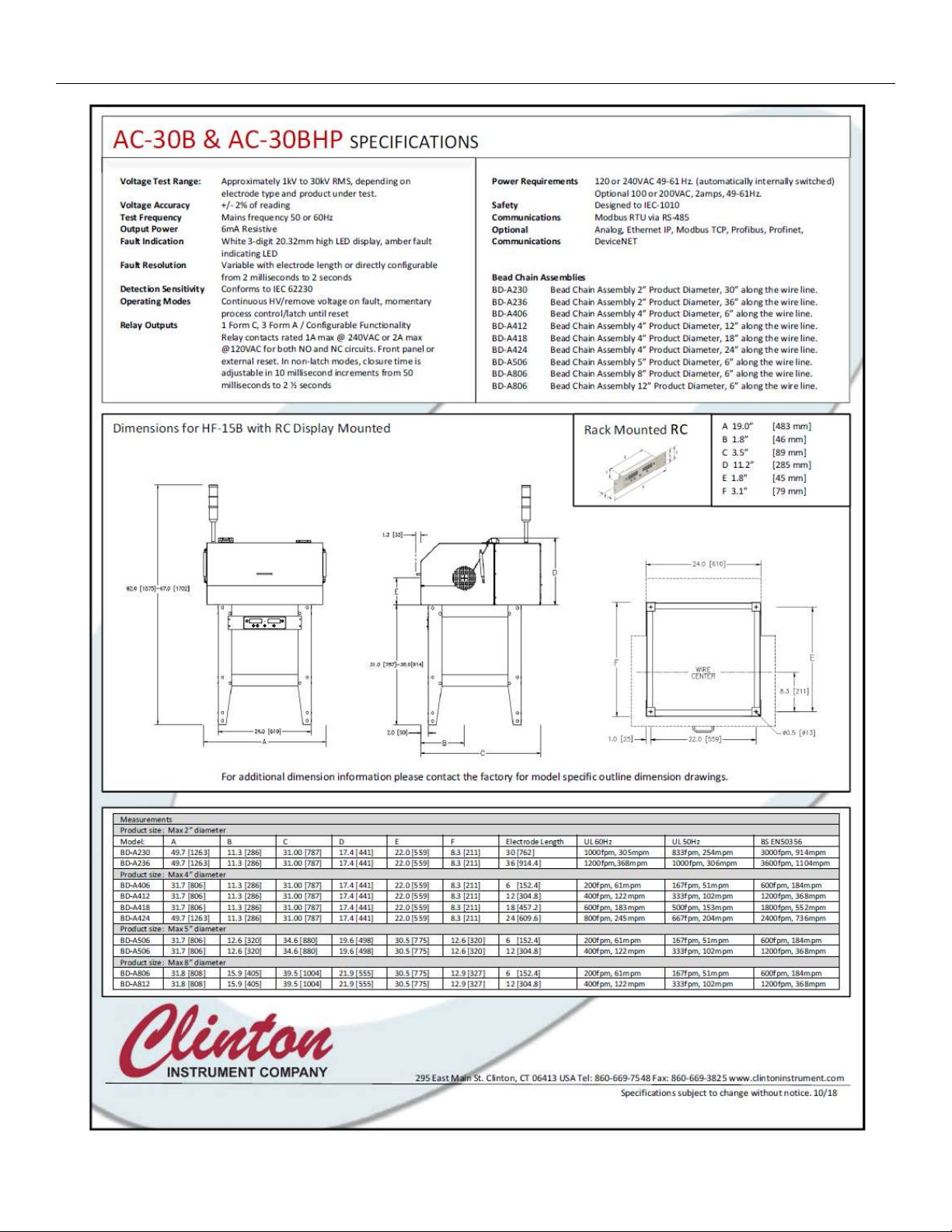
SPECIFICATIONS ................................................................................................................................................................................6
SAFETY ..............................................................................................................................................................................................8
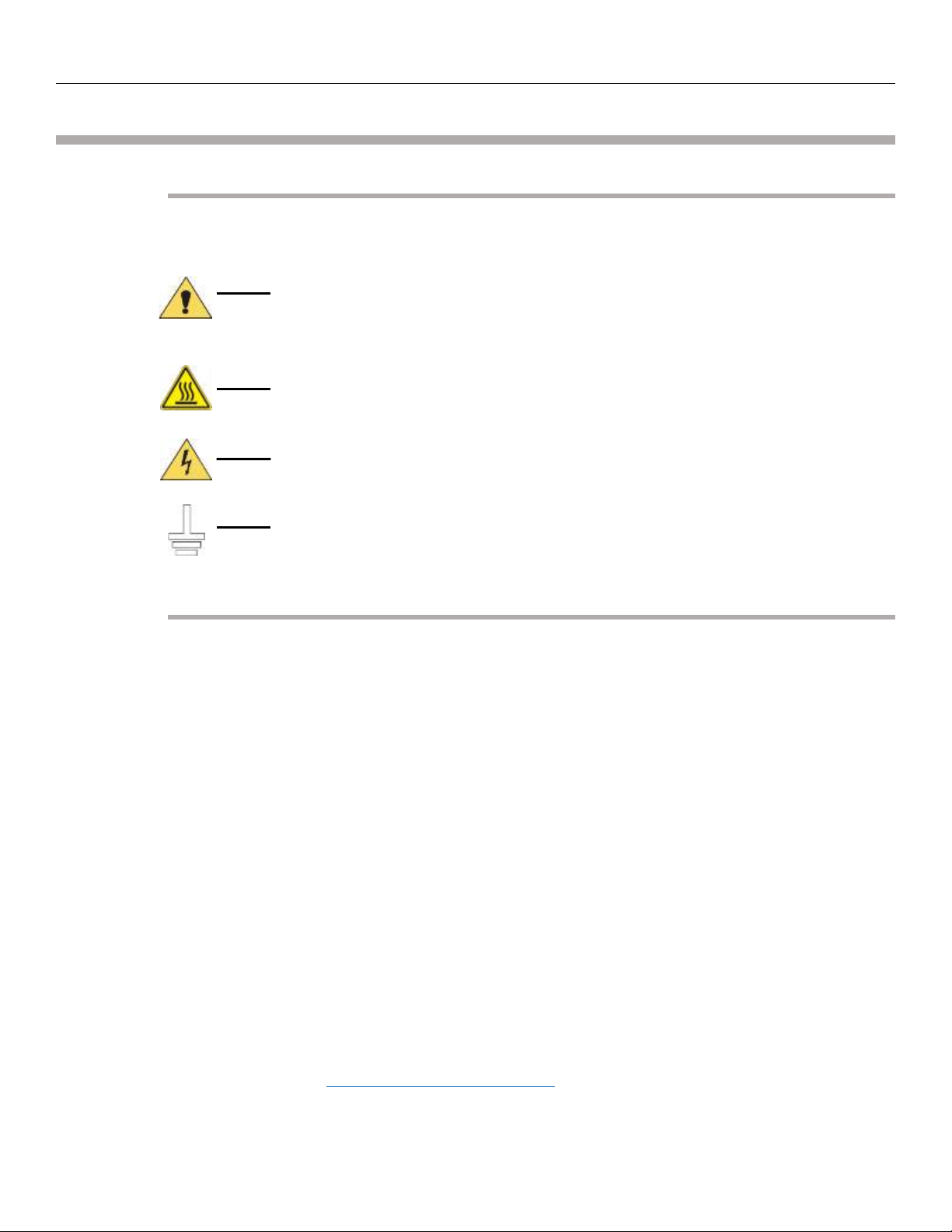
SAFETY SYMBOL .........................................................................................................................................................................................8
ENVIRONMENTAL CONDITIONS......................................................................................................................................................................8
AVOID THE RISK OF FIRE! .............................................................................................................................................................................9
CAUTION:PACEMAKER WARNING .................................................................................................................................................................9
CAUTION:OZONE PRODUCTION ....................................................................................................................................................................9
ELECTRICAL SHOCK HAZARD FROM PRODUCTION LINE SPARK TESTERS................................................................................................................ 10
INSTALLATION .................................................................................................................................................................................11
CAUTION:.............................................................................................................................................................................................11
UNPACKING.............................................................................................................................................................................................11
SITE PREPARATION....................................................................................................................................................................................12
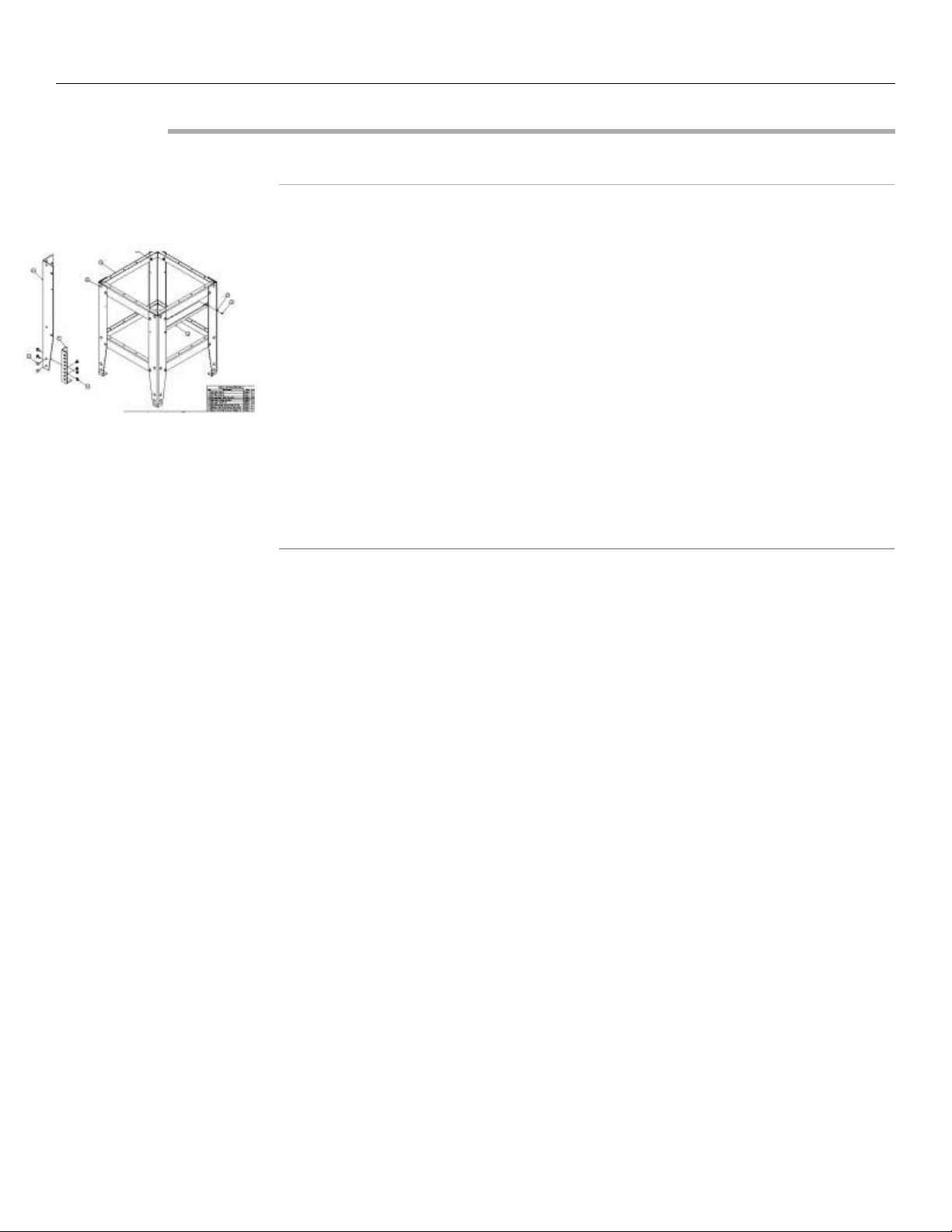
Select a suitable location for the spark tester: ................................................................................................................................12
Select a suitable location for the spark tester: ................................................................................................................................12
RC Control Unit:............................................................................................................................................................................... 13
X3B Horn/Light Tower: ....................................................................................................................................................................13
Provide for ventilation of the Test Module......................................................................................................................................13
POWER WIRING .......................................................................................................................................................................................13
Install an external disconnecting device..........................................................................................................................................13
Mains Power....................................................................................................................................................................................14
Ground the Spark Tester.................................................................................................................................................................. 14
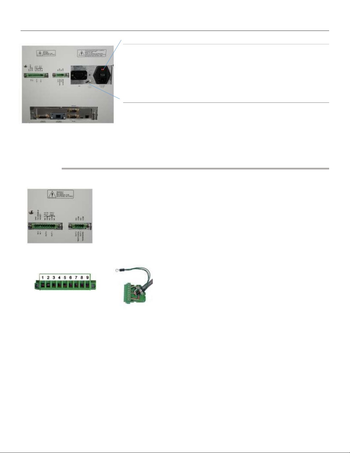
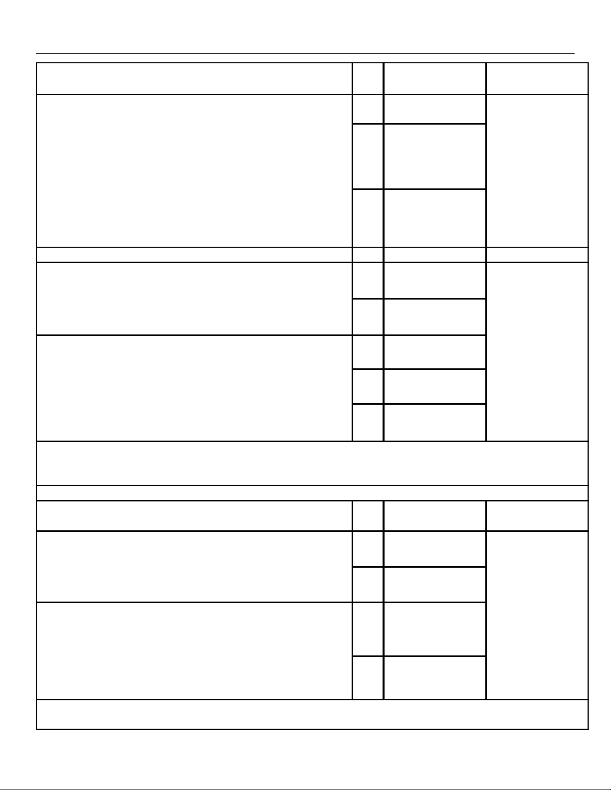
TERMINAL BLOCK WIRING..........................................................................................................................................................................14
CONNECTING THE SERIAL RS-485 ...............................................................................................................................................................16
CONNECTING TO THE ANALOG INTERFACE .....................................................................................................................................................16
INSTALLING THE COMPACTCOM™MODULE ..................................................................................................................................................16
CONNECTING THE X3B ..............................................................................................................................................................................17
Unpacking the X3B ..........................................................................................................................................................................17
Connecting the X3B .........................................................................................................................................................................17
X3B to Spark Tester Connections.....................................................................................................................................................18
SPARK TESTER CONTROLS ...............................................................................................................................................................19
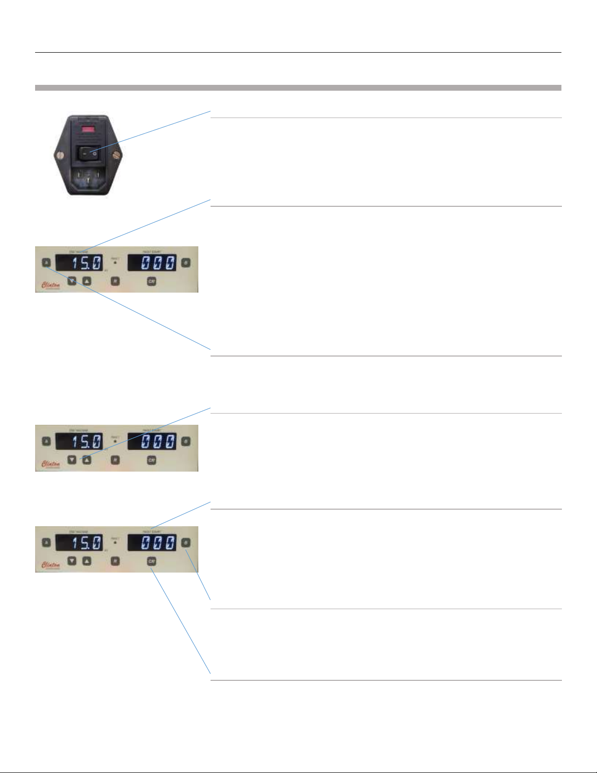
ON/OFF Power Switch .....................................................................................................................................................................19
Voltmeter ........................................................................................................................................................................................ 19
“A” Button .......................................................................................................................................................................................19
UP/DOWN ARROW (VOLTAGE ADJUST) buttons.............................................................................................................................19
Fault Counter...................................................................................................................................................................................19
“B” Button .......................................................................................................................................................................................19
“CR” COUNT RESET button ..............................................................................................................................................................19
FAULT light ...................................................................................................................................................................................... 20
“R” RESET button............................................................................................................................................................................. 20
High Voltage On Lamp ....................................................................................................................................................................20
Safety Interlock switch ....................................................................................................................................................................20
Protective Cover ..............................................................................................................................................................................20
Bead Chain Electrode ......................................................................................................................................................................20
DEFINITION OF TERMS ....................................................................................................................................................................21