Clinton FL-8A User manual

Clinton Instrument Company
295 East Main Street
Clinton, CT 06413 USA
Telephone: 860.669.7548 Fax: 860.669.3825
www.clintoninstrument.com
Model FL-8A Portable Cable Fault Locator
Instruction Manual

Rev D 2/15

MODEL FL- 8A
Portable Cable Fault Locator
Long lengths of cable used in land drilling, offshore well
development and production, marine and ROV applica-
tions are routinely subject to mechanical shock as well as
electrical and thermal stress. Damage to these multi-conduc-
tor constructions, which may contain crucial power, control
signal and video conductors, can result in down time and
costly cable replacement.
To meet the needs of these applications, Clinton has
developed the Model FL-8A, a battery operated cable fault
locator that can be used on site to accurately pinpoint opens
and shorts in these cables. Built to withstand a demanding
environment, the unit performs a quick, automated test.
The operator simply connects the FL-8A test probes to
each end of the damaged cable, enters the cable length on
the digital touch screen, and selects “Shorts” or “Opens” to
begin the test. The unit quickly calculates the distance of the
fault site from each test probe, displays the location in feet or
meters, and provides a suggested trim area. The failure can
then be cut out or repaired and the remaining good product
reused. Many times, most of the cable can be recovered and
>> Battery operated cable fault locator
>> Quickly locates opens, shorts and high
voltage shorts in cable lengths
>> Robust design for harsh environments
>>Fully automated testing
>> Color touch screen
put back into service.
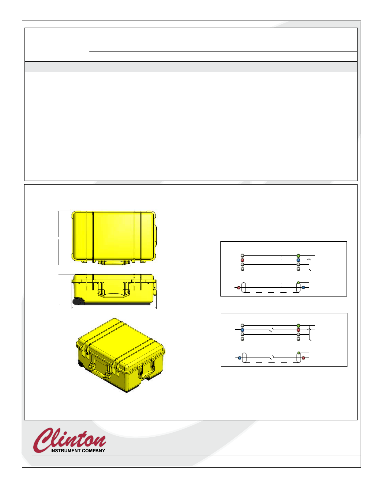
The FL-8A Cable Fault Loca-
tor is a compact 43 lbs. built into a
sturdy wheeled case. It promises a
great return on investment by ana-
lyzing expensive cable assemblies
with speed and accuracy.
Sample display screens
295 East Main St. • Clinton, CT 06413 USA • Tel: 860.669.7548 • Fax: 860.669.3825 • www.clintoninstrument.com
Fault Definitions:
Open.. ................................ A condition where a single conductor has no
continuity from one end to the other.
Metallic Short ...................... Two conductors without insulation or a conductor and
a shield which physically come into contact with one
another.
High Voltage Short .............. Two conductors or a conductor and a shield which
have no insulation between them but do not contact
one another.
Voltage Test Range ..............0-8 KV D.C.
Display ............................... 6-inch backlit color TFT touch screen.
Output Current .....................6 ma. maximum.
FL- 8A
SPECIFICATIONS
Equipment Accuracy .............Better than 1% of total cable length (dependent on
accuracy of actual cable footage and product uniformity).
Cable Loop Resistance
Metallic Short .............50 milliohms minimum.
High Voltage Short ......300 milliohms minimum.
Dimensions ......................... 22.0”W x 18.2”D x 10.4”H.
Test Leads ...........................10’ long.
Weight ...............................43 lbs. (19.5 kg.).
Battery Power ......................Ni-MH 24V 5Ah, rechargeable through FL-8A power cord.
Recharge Power ...................100 - 240 volts AC, 50/60 Hz 2 amps.
*dependent on accuracy of actual cable footage and product uniformity.
Specifications subject to change without notice. 11/11 EN
z
Shorts
z
TypicalLeadConnections
Opens
Green
Blue
(GroundStrap)
Green
Blue
Red
Red
CoaxialCable
TopofReel Bottomofreel
MultiConductorCable
Green
(GroundStrap)
Green
CoaxialCable
TopofReel Bottomofreel
MultiConductorCable
Blue Red
Blue Red
1
1
2
2
3
3
4
4
A A
B B
C C
D D
DWG NO:
ALL DIMENSION I N INCHES:
TOLERANCES:
FRACTIONAL: ±1/64
DECIMAL:
2P LACES: ±.015
3P LACES: ±.010
ANGULAR: ±1
~
UNLESS OTHERWIS E NOTED
USED IN:
APPROVED:
11/4/2011
DRAWN:
tlane
1560Case
C
DATE:
295 EAST MA IN STREET, CLINTON, C T 06413
PHONE: (860) 66 9-7548 FAX: (860) 669-3825
THIS DRAWING IS THE P ROPERTY
OF THE CLINTON INSTRUMENT
COMPANY, INC. THE INFO RMATION
CONTAINED HEREON M AY NOT
BE REPRODUCED OR DIS TRIBUTED
WITHOUT THE EXPR ESS PER-
MISSION OF T HE CLINTON
INSTRUMENT CO .
the clinton instrument company
linton
C
TITLE:
SIZE SHEET
1
OF
2
CHECKED QA: REV
22.10 / 561.4
10.37 / 263.4
18.15 / 461.0
1
1
2
2
3
3
4
4
A A
B B
C C
D D
DWG NO:
ALL DIMENSION IN IN CHES:
TOLERANCES:
FRACT IONAL: ±1/64
DEC IMAL:
2 PLA CES: ±.015
3 PLA CES: ±.010
ANGULAR: ±1
~
UNLESS OTHERWISE N OTED
USED IN:
APPROVED:
11/4/2011
DRAWN:
tlane
1560Case
C
DATE:
295 EAST MAIN ST REET, CLINTON, CT 0 6413
PHONE: (860) 669-7 548 FAX: (860) 669-3825
THIS DRAWING IS THE PRO PERTY
OF THE CLINTON INSTRU MENT
COMPANY, INC. THE INFOR MATION
CONTAINED HEREON MAY N OT
BE REPRODUCED OR DISTR IBUTED
WITHOUT THE EXPRES S PER-
MISSION OF T HE CLINTON
INSTRUMENT CO.
the clinton instrument company
linton
C
TITLE:
SIZE SHEET 2 OF 2
CHECKED QA: REV
FL-8A Dimensions

Table of Contents
Safety ........................................................................................................................................ 1
Installation ............................................................................................................................... 4
Denitions ............................................................................................................................... 5
FL-8A Controls....................................................................................................................... 7
Settings Menu.......................................................................................................................... 8
Testing Large Cables with the FL-8A................................................................................13
Performing a Shorts Test.....................................................................................................14
Performing an Open Tests.................................................................................................. 16
Performing a Hi-Pot Test .................................................................................................... 18
Calibration .............................................................................................................................20
Maintenance ..........................................................................................................................22
How to Use the 91785 FL Test Box.................................................................................. 23
Cable Capacitance Chart......................................................................................................25
Cable Loop Resistance Chart..............................................................................................26
Replacement Parts ................................................................................................................27
Troubleshooting....................................................................................................................28
“Electric Shock Considerations for Electric Vehicle Charging Systems”.................... 29
Warranty.................................................................................................................................36

FL-8A Instruction Manual - Page 1
Model FL-8A Portable Cable Fault Locator
Safety
Danger! High Voltage Safety Hazards
Caution--Read before using this equipment.
DISCHARGE ALL CONDUCTORS OF THE TEST CABLE
PRIOR TO CONNECTING TO THE FL-20A. YOU MUST
REMOVE ANY STORED CHARGE FROM THE PREVI-
OUS OPERATION, SUCH AS A HI-POT TEST. A STORED
CHARGE IN THE CABLE CAN KILL!!!
The FL-20A employs high voltage to locate cable faults. It is imperative
that only personnel trained in the dangers of high voltage operate this
equipment. A stored charge in the TEST PRODUCT can be lethal,
even when the cable is no longer attached to the FL-20A. Please read
and understand the manual prior to operating this equipment.
A Warning to Supervisors!
The FL-8A is equipped with such safety features as internal safety inter-
locks, a red High Voltage Present warning light, grounding sensors, and
password protection. Do not attempt to defeat or bypass any safety
feature. Failure to observe proper safety precautions can result in severe
injury or death!
Supervisory personnel are strongly advised to use the built-in password
protection feature to prevent unauthorized persons from defeating
safety features or changing test parameters. Read the section in Installa-
tion entitled, “Password Protection,” for further information.
A Warning Note to Operators!
When cables are being tested with this or any high voltage equipment,
the possibility of leaving a dangerous charge in the cable is always pres-
ent. Always bunch together and ground all conductors not under test,
including to the cable shield and to the earth ground, using the provided
ground probe. Make sure the test is complete, that the high voltage indi-
cator lamp is off, and that all leads are shorted to ground before touching
any part of the cables.
Although the high voltage output of the FL-8A is not in itself capable
of delivering a truly dangerous shock, a stored charge in the cable can, if
proper safety precautions are not taken. For this reason, operators and
supervisors should establish rigid safety procedures for the use of this
and all high voltage equipment.

Page 2 - FL-8A Instruction Manual
Model FL-8A Portable Cable Fault Locator
High Voltage Facts
The commonly accepted maximum values of 60 Hz. current passing
through the human adult body which permit a subject to let go of elec-
trodes are nine milliamperes for males and six milliamperes for females.
At 3000 Hz. this value increases to about 22 milliamperes for men or 15
milliamperes for women. DC currents do not present the same let–go
problems, but a subject can readily let go at a level of 60 milliamperes.
A continuous 60 Hz. current above 18 milliamperes stops breathing for
the duration of the shock only. Ventricular brillation may occur above
a level of 67 milliamperes. The reaction current level of 60 Hz. is about
.5 milliamperes. Above this level a muscular reaction can occur which
can cause a secondary accident. The DC and 3 kHz. levels are probably
considerably higher.
Capacitor discharge energy of 50 Joules (watt–seconds) is regarded as
hazardous.
For references, see: Dalziel, Ogden, Abbot, “Effect of Frequency on
Let–Go Currents,” Transactions of A.I.E.E., Volume 62, December
1943, and Dalziel, “Electric Shock Hazard,” I.E.E.E., Spectrum, Febru-
ary 1972.
Safety Symbols
The symbols depicted below are safety symbols placed on the spark test
equipment. It is important to understand the meaning of each.
The Caution symbol found in the instruction manual calls attention to
a procedure, practice, or the like, which if not correctly performed or
adhered to, could result in personal injury or damage to or destruction
of part or all of the product. Do not proceed beyond a Caution symbol
until the indicated conditions are fully understood and met.
Risk of electric shock symbol.
Earth (ground) symbol.
Environmental Conditions
The Model FL-8A Cable Fault Locator is designed to be safe under the
following conditions:
• Altitude to 2000 m.
• Temperatures from 5ºC to 40ºC.
• Humidity to 80% R.H. at 31ºC, decreasing linearly to 50% R.H. at
40ºC.

FL-8A Instruction Manual - Page 3
Model FL-8A Portable Cable Fault Locator
The Clinton Instrument Company certies that this equipment met its
published specications at the time of shipment. Clinton further certi-
es that its calibration measurements are traceable to the United States
National Institute of Standards and Technology to the extent allowed
by the Institute’s calibration facility. For customer service or technical
assistance with this equipment, please contact:
The Clinton Instrument Company
295 East Main Street, Clinton, CT 06413 USA
Telephone: 860-669-7548 Fax: 860-669-3825
Website: www.clintoninstrument.com.
email: support@clintoninstrument.com.
Page 4 - FL-8A Instruction Manual
Model FL-8A Portable Cable Fault Locator
Installation
Unpacking
The following items are included in the shipment:
• FL-8A Cable Fault Locator, with a set of 3 test probes (red, blue and
green) and power cord attached
• 91785 FL Test Box
• (3) 92100 Probe Clip Assemblies (other sizes available)
• An instruction manual
Remove the FL-8A from the carton. Retain the packing material in the
event that the unit is returned for calibration or service at some future
time.
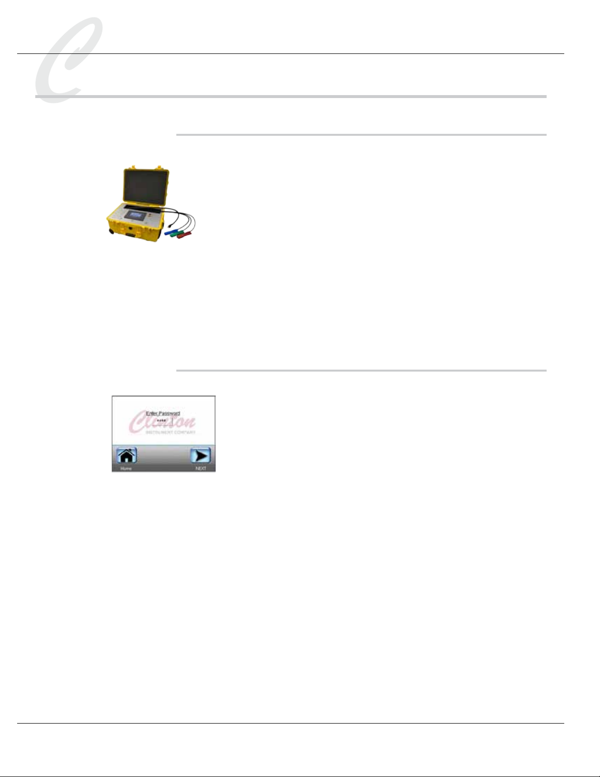
Password Protection
The FL-8A offers password protection that can prevent unauthorized
individuals from defeating safety features and changing voltage settings
and test parameters. Using password protection will make your work-
place safer.
After making necessary changes in the Settings menu, go to the Set
Admin Password setting. The default password is 1111. To change it,
press the displayed password to access a keypad. Enter a new 4-digit
password and press OK.
After entering a new password, go to the Lock Settings Menu function
and turn it ON. This will restrict unauthorized personnel from access-
ing the Settings menu. If the new password should be lost, contact the
factory.

FL-8A Instruction Manual - Page 5
Model FL-8A Portable Cable Fault Locator
Denitions
Shorts
Metallic short
A condition where there is direct metal-to-metal contact between two con-
ductors.
High voltage short
Two conductors without insulation, or a conductor and a shield with no
insulation between them, where there is no direct contact. The condition is
detected only at high voltage when arcing occurs between conductors.
Intermittent arc
An intermittent arc is a high voltage short present that breaks down margin-
ally at the selected hi-pot voltage.
Opens
An open is a condition where a single conductor has no continuity from one
end to the other.
Hi-Pot Test
Also called a dielectric withstand test. The purpose of this test is to charge
one conductor to determine if high voltage at a predetermined level will
discharge to ground through the insulation. If too much current ows, the
conductor is not well insulated and it fails the test.
Loop Resistance
Conductor resistance to the ow of electrical current, measured in
ohms/1,000 feet. Resistance is inversely proportional to the cross-sectional
area of the conductor, so when the diameter of the conductor is doubled, the
resistance declines 50 percent. FL-8A tests for metallic shorts are accurate
on conductors with loop resistances of 50 milliohms or greater. Tests for
high voltage shorts are effective on conductors with resistances of 200-250
milliohms or greater.
Accuracy
The accuracy of the test performed. Ratings are inuenced by cable charac-
teristics such as low loop resistance. Accuracy is reported as follows:

Page 6 - FL-8A Instruction Manual
Model FL-8A Portable Cable Fault Locator
Low
There may be multiple faults in the cable, the cable may have low loop
resistance, or the fault is judged to be close to either end.
Standard
The test is considered good, with good results.
Exceptional
The fault location was easily located, and test results are accurate within
1% of the cable length.
FL-8A Instruction Manual - Page 7
Model FL-8A Portable Cable Fault Locator
FL-8A Controls
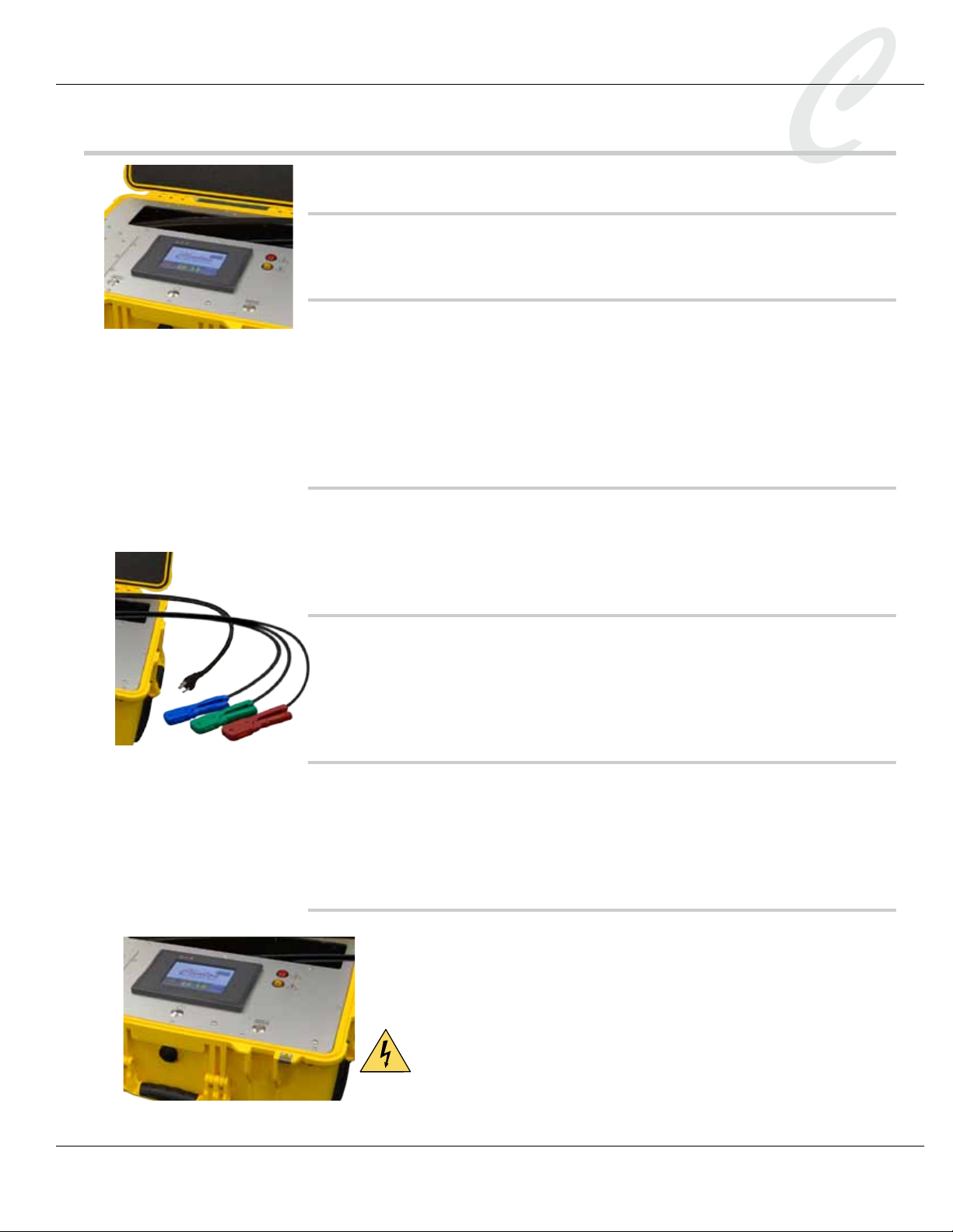
ON/OFF power switch
This switch is located beneath the front panel touch screen.
Front panel touch screen
The touch screen is used to set test parameters, run tests, view the bat-
tery level, and test results. Never press the touch screen with a tool or
sharp object.
The screen will turn OFF after a period of inactivity. Simply touch the
screen to turn ON the display.
Safety buttons
Located on each side of the FL-8A front panel, the safety buttons must
be held in during a shorts or hi-pot test. This is a safety feature that
prevents the operator from touching the charged test cable during a test.
Red and blue test probes
The red probe will connect to one end of a test conductor, and the blue
probe to the opposite end. Review the instructions in the Installation
section on how to properly strip back the conductors and insert them
into the probes. This is an important safety procedure.
Green ground probe
The green ground probe is used to make connections to the reference
conductor and to ground the test cable. Review the instructions in the
test sections on how to properly strip back the conductors and insert
them into the probe. This is an important safety procedure.
Indicator Lights
The FL-8A front panel has two indicator lights. The yellow Test In
Progress light will ash during a test. The red High Voltage Present light
will illuminate when high voltage is present at the probes. Both lights
will ash during the power up sequence.
Warning: when the red High Voltage light is illuminated, do not
touch the red and blue probes or the test cable, because a charge is
present. If the cable capacitance is large, the light may be illumi-
nated for several seconds after the test is complete.

Page 8 - FL-8A Instruction Manual
Model FL-8A Portable Cable Fault Locator
Settings Menu
Test parameters are found on the touch screen Settings menu. They are
saved in memory even when the FL-8A is off. To view or change test
parameters, turn on the FL-8A power switch, which is located on the
front panel. The FL-8A will take a few moments to boot up. Do not
touch the screen until the Clinton logo appears. The main menu will
appear.
Press the Settings button.
The Password Entry screen will appear. Click inside the Password box
and enter the password on the keypad and press OK. The default pass-
word is 1111. Press NEXT. (If you wish to change the password, go to
Set Admin Password, on a later page of the Settings menu.)
The rst page of the Settings menu will appear.
Press Pg Down to the next few pages of the Settings menu to access the
following global settings: Calibration, Language, and Unit of Measure.
These settings apply to all Opens, Shorts and Hi-Pot Testing.
Global Settings
Global settings such as Calibration, Language, and Unit of Measure
apply to Opens, Shorts and Hi-Pot tests. They are found in the several
pages of the Settings Menu. To view or modify a setting, press the
appropriate button to access the subscreen. Addtional screens such as
System Information, System Errors, Set System Defaults, and Set Admin
Password are also included in the Settings menu.
Calibration
This setting allows the user to calibrate the FL-8A output voltage and
voltage reporting. Refer to the section entitled,”Calibration,” for specic
instructions.
Language
Flag icons representing the languages that are available on the FL-8A are
displayed here. The languages are English, Japanese, Spanish, German,
French, Italian, Swedish, and Chinese. Press the ag icon of your choice.
The default setting is English.

FL-8A Instruction Manual - Page 9
Model FL-8A Portable Cable Fault Locator
Unit of Measure
Test cable lengths may be displayed in feet or meters. The unit of
measure cannot be changed during a test. Press the displayed choice to
toggle between Feet or Meters.
System Information
FL-8A rmware and software version numbers are stored here. During
troubleshooting, you may be asked for this information by a Clinton
technician.
System Errors
System error information is stored here. A Clinton technician may
request that you access this information during troubleshooting.
Set System Defaults
The Set System Defaults RESTORES system defaults. Restoring System
Defaults does not affect calibration.
Set Admin Password
When Lock Settings is ON, a password is required to access the Set-
tings menu. Reserving global setting access to supervisory personnel
prevents unauthorized individuals from changing test parameters or
defeating safety features. The default password is 1111. To change it,
press the displayed password to access a keypad. Enter a new 4-digit
password and press the check mark/accept button.
After changing the password, turn Locked Settings Menu ON to pre-
vent unauthorized access to the Settings menu.
Note: change the Password before you turn ON the Lock Settings
Menu option.
Lock Settings Menu
When Lock Settings Menu is ON, you will be required to enter the
admin password to access the Settings menu. If the password is lost,
contact the factory. The default setting is OFF.
Set Date and Time
If printed report information with date and time is required, enter the
current date and time. The FL-8A will retain this setting in memory,
even when it is turned OFF.
Page 10 - FL-8A Instruction Manual
Model FL-8A Portable Cable Fault Locator
Shorts Parameters
Shorts Parameters are accessed from the Settings menu. The rst page
of the Shorts Parameters settings will appear. These settings will apply
to all shorts tests that will be done. They are saved in memory even
when the FL-8A is off.
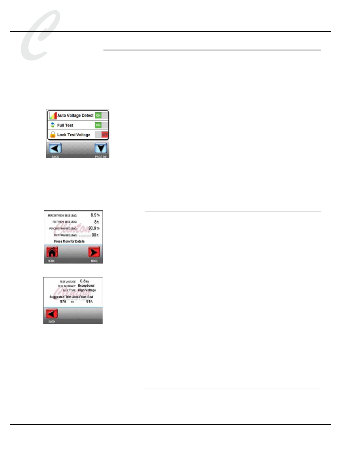
Auto Voltage Detect
During the shorts test, the optimum voltage level is the test voltage
required to cause a fault to arc to ground, not higher. When Auto Voltage
Detect is ON, the fault locator will begin testing the conductor at 10% of
the Shorts Max Voltage and increase it by 10% increments until a short is
found. For example, if Shorts Max Voltage is set at 8KV, the test voltage
begins at .8KV and rises by .8KV until a short is found.
This feature can prevent damage to the cable by testing at the lowest
possible voltage. It also may be useful when multiple high voltage shorts
are present, since one short may arc at a lower test voltage than another.
When the rst short is detected, it can be cut out of the cable, and the
test can be resumed to locate the second short.
Full Test
When this setting is ON, the equipment will rst locate the distance of
the short from the red probe, and then nd its distance from the blue
probe. A summary screen showing the distance of the fault from each
probe will display. The total of the two distances should equal the length
of the test cable. By pressing MORE, the operator may view the rated
accuracy of the results as well as a suggested cable area to remove. The
full report may be printed.
When the setting is OFF, the FL-8A performs only a partial test, nding
the distance of the short from the red probe and then pausing to display
a report. You may press BACK to terminate the test, but the test’s accu-
racy is, at this point, unknown. If you instead press NEXT, the FL-8A
will then proceed to nd the distance of the short from the blue probe.
A summary screen showing the short’s location from the red and blue
probes, as well as the rated accuracy of the test and the suggested trim
area, will display.
The default for Full Test is ON. Experienced operators working with a
particular cable type are sometimes condent that a partial test is accurate
and choose it to reduce test time. However, this is not recommended
without the advice of a Clinton technician.
Lock Test Voltage
When this setting is ON, the Shorts Max Voltage setting cannot be
changed at test time, although the voltage setting is displayed during the
test.
FL-8A Instruction Manual - Page 11
Model FL-8A Portable Cable Fault Locator
Shorts Max Voltage
This setting is found on the second page of the Shorts Parameters set-
tings. This is the maximum voltage that will be applied during the shorts
test. An entry of 8.0 represents 8KV DC. To change the setting, press
the existing value to view a keypad. Enter the new value, using the deci-
mal point and press OK.
If this value is set too high, damage to the cable may result. If the maxi-
mum voltage is set too low, a high voltage short may not arc and cannot
be located.
Shorts Max Voltage can be changed at the time of test if Lock Test
Voltage is OFF.
Opens Parameters
Access the Open Parameters settings from the Settings menu. They
apply to opens tests that will be done. They are saved in memory even
when the FL-8A is off. The default settings are usually optimum for
opens testing. It is not advisable to change them, except the Auto
Reverse Leads setting, without factory advice.
Auto Frequency Select
When this setting is ON, the FL-8A will automatically nd the optimum
frequency at which to test. When the setting is OFF, it will test at the
Set Frequency, which may not give you correct results. The default set-
ting is ON.
Full Test
When this setting is ON, the equipment will rst locate the distance
of the open from the blue probe, and then nd its distance from the
red probe. A summary screen showing the distance of the fault from
each probe will display. The total of the two distances should equal the
length of the test cable. By pressing MORE, the operator may view the
rated accuracy of the results as well as a suggested cable area to remove.
The full report may be printed.
When the setting is OFF, the FL-8A performs only a partial test, nding
the distance of the open from the blue probe and then pausing to dis-
play a report. You may press BACK to terminate the test, but the test’s
accuracy is, at this point, unknown. If you instead press NEXT, the
FL-8A will then proceed to ind the distance of the short from the red
probe. A summary screen showing the open’s location from the red and
blue probes, as well as the rated accuracy of the test and the suggested
trim area, will display.
Page 12 - FL-8A Instruction Manual
Model FL-8A Portable Cable Fault Locator
The default for Full Test is ON. Experienced operators working with a
particular cable type are sometimes condent that a partial test is accurate
and choose it to reduce test time. However, this is not recommended
without the advice of a Clinton technician.
Lock Test Frequency
When this setting is ON, the FL-8A will not prompt the user to enter a
test frequency before the Opens test. The default setting is ON.
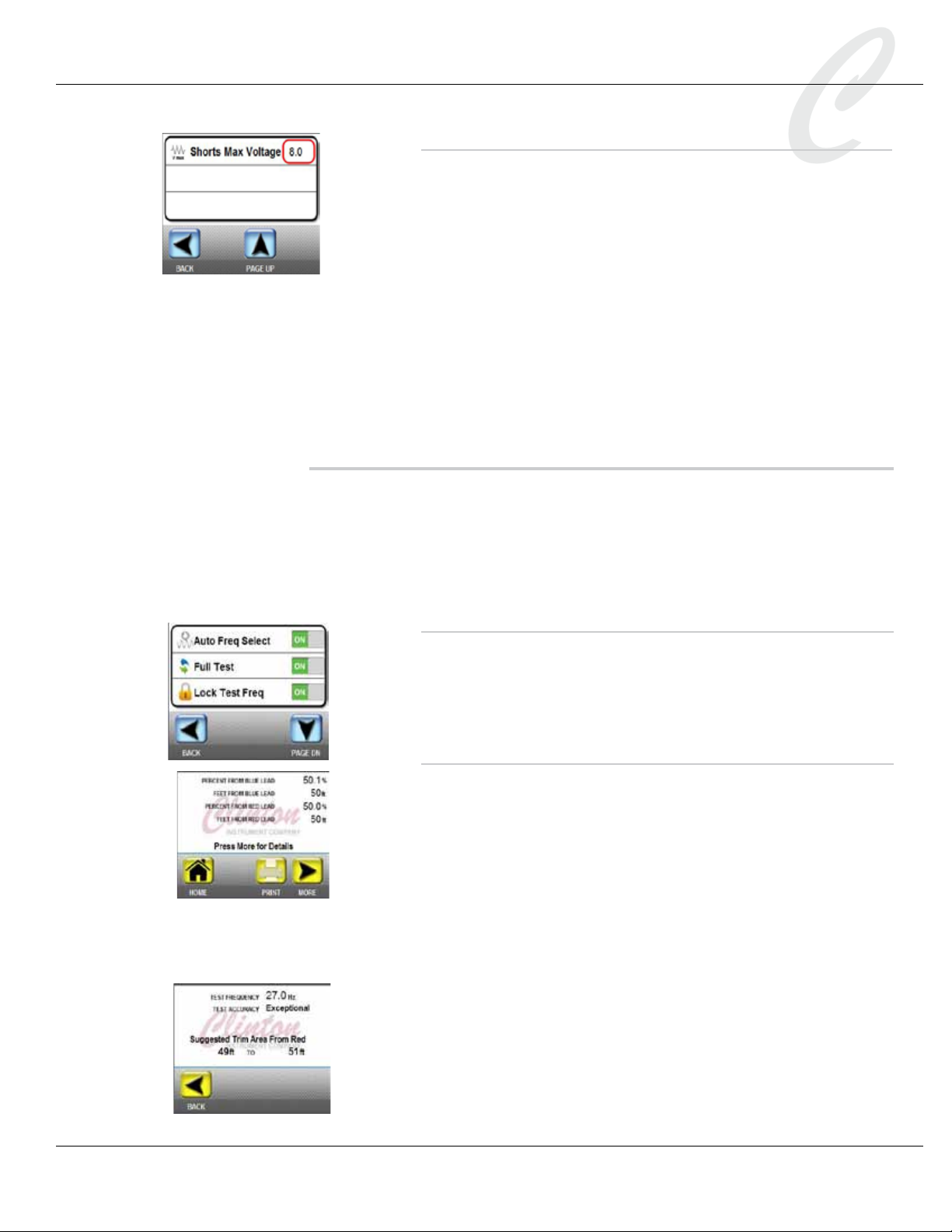
Opens Start Frequency
This setting is found on Page 2 of the Opens Parameters menu. It is the
frequency applied during the Opens test. The default setting is 23.0 Hz.
Do not change this frequency without factory advice.
Hi-Pot Parameters
Access Hi-Pot parameters from the Settings menu.
Lock Hi-Pot Settings
When Lock Hi-Pot Settings is OFF, the user can change the values that
are entered in the Hi-Pot Parameters menu during a Hi-Pot test. When
Lock Hi-Pot Settings is ON, the operator cannot change the parameters
during the test. The default setting is OFF.
Vmax (kV)
This is the maximum Hi-Pot test voltage. The range is 1.0kV to 8.0kV.
This setting can be changed here to affect all Hi-Pot tests, or at the time
of test if Lock Hi-Pot Settings is OFF.
Vsteps (#)
This is the number of steps the Hi-Pot test will take to get to Vmax (kV),
the maximum Hi-Pot voltage. The number is between 2 and 20. This
setting can be changed here to affect all Hi-Pot tests, or at the time of
test if Lock Hi-Pot Settings is OFF.
Vramp Time (s)
This setting is found on page 2 of the Hi-Pot parameters menu. This is
the time, in seconds, up to 6000 seconds, that the FL-8A will take to per-
form each one of the Vsteps to get to the preset maximum Hi-Pot volt-
age (Vmax (kV)). This setting can be changed here to affect all Hi-Pot
tests, or at the time of test if Lock Hi-Pot Settings is OFF.
Vhold Time (s)
This is the time, in seconds, that the FL-8A will stay at Vmax (kV), the
maximum test voltage, before the test ends. The maximum Vhold Time
(s) is 6000 seconds. This setting can be changed here to affect all Hi-Pot
tests, or at the time of test if Lock Hi-Pot Settings is OFF.
FL-8A Instruction Manual - Page 13
Model FL-8A Portable Cable Fault Locator
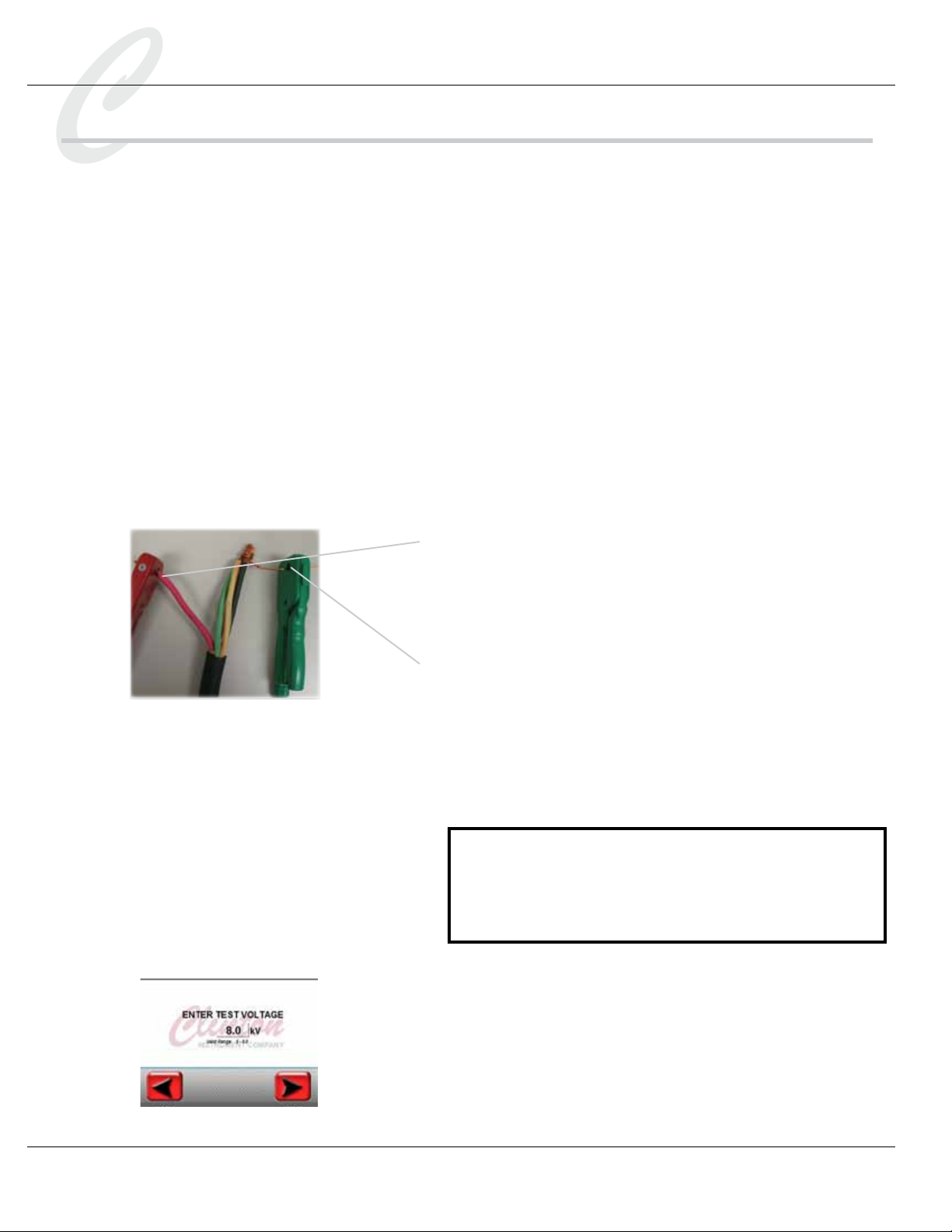
Testing Large Cables with the FL-8A
If conductors are too large to insert into the probes, special attention
must be paid to insure that proper connections are made. Poor connec-
tions can be dangerous to personnel. Additionally, the FL-8A graphics
display may not function correctly due to excess electrical noise created
by improper grounding.
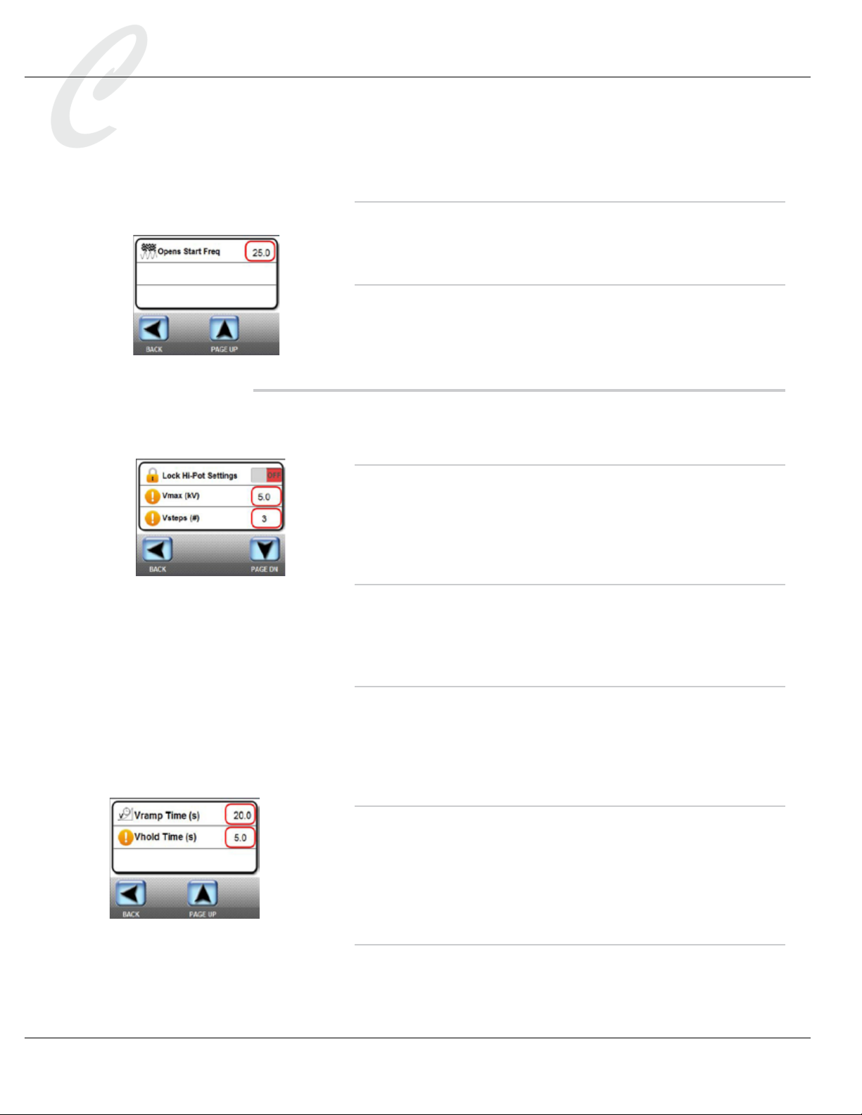
Alligator clip assemblies similar to those shown in the photos below are
highy recommended when cables to be tested are too large to t properly
in the probes. These items are available for purchase. Smaller cable sizes
can use the enclosed 3 probe clip assemblies part number 92100. Larger
cables may require part number 92113.
Page 14 - FL-8A Instruction Manual
Model FL-8A Portable Cable Fault Locator
Performing a Shorts Test
Caution. DANGER!!!
It is imperative that only personnel trained in the dangers of high voltage
operate this equipment. A stored charge in a test cable can kill! A charge
can remain in a cable if the cable has not been properly discharged, even
when it is no longer attached to the FL-8A. Discharge all conductors
of the test cable prior to connecting to the FL-8A to remove any
stored charge from a previous operation. A stored charge in the
cable can be lethal.
Note: to determine the accuracy of the Shorts test that you can expect
on your test product, please refer to the chart entitled, “Cable Loop
Resistance Chart.”
1. Review the Shorts Parameters settings that have been entered
before proceeding with the test. They are found in the Settings
menu.
2. Select the rst conductor to be tested. Strip back by 1” and
insert the exposed conductor into the red test probe. Be sure
that insulation does not obstruct the connection between the
metal in the probe and the exposed conductor. Strip the other
end of the conductor and insert into the blue test probe.
3. Ground all untested conductors. On one end of the test cable,
strip back all conductors not under test by 1”, carefully bunch
them together with the cable shield so that they make a good
connection with one another, and insert into the green ground
probe. Be sure that insulation does not obstruct the connec-
tion between the metal in the probe and the exposed conduc-
tors. Do not attempt to bypass this safety procedure. Failure to
observe safety precautions can result in severe injury or death!
NOTE: If conductors are too large to insert into the probes,
see the section entitled, “Testing Large Cables with the FL-8A.”
It is critical that conductors be connected properly. Poor con-
nections can be dangerous to personnel; additionally, the FL-8A
graphics display may not function correctly due to noise.
4. At the main menu, press the Shorts button to begin a test for
high voltage shorts or metallic shorts. The screen will guide you
through the test.
5. Enter the maximum test voltage. (If the Lock Test Voltage set-
ting is ON, this screen will not be displayed.)
Table of contents
Other Clinton Test Equipment manuals


